Note: Descriptions are shown in the official language in which they were submitted.
wo94/06366 ~ 4~9 Pcr/US93/08203
PORTABLE STERILIZABLE WATER SUPPLY FOR DENTAL APPLIANCES
BACKGROUND OF 'l H ~ INVEN IION
Field of the Invention
The invention is in the field of supplying sterile water or other sterile dentalsoll-tion~ through dental appli~nres in a portable standardly connect~hle unit.
Background of the Invention
The dental practice is increasingly concerned with the ne~e~s;ly of m~int~ining a
sterile meAic~l environment for the patient. The dental handpiece is most commonly an air
operated turbine driven drill which nPres~rily includes a misting spray of cooling water to
avoid heat buildup from friction gene~tPIi during the drilling operation. Suction devices and
dental syringes are employed to wash down and air dry the work area in the patient's mouth.
Conventional dental handpieces and the syringes have eYte-nd~P~ length tubing h~rnP~çs which
are connP~ted to a stand mounted near the dentist's chair and supplied with a common source
of potable water and ~l~s~u~;7ed op~ldling air. Coolant and rinse fluids are neces$~.;ly
introduced into the patient's oral cavity. Many standard dental procedures require t;A~osu,e
of the patient's blood system to these fluids through incisions, root canals and other standard
dental operations.
In addition to the fact that the potable water supply is not really sterile, and can
itself introduce microbial org~ni~m~ to the patient, there is an increasingly serious concern
about the possibility of cross-con~ in~t;on occurring from patient to patient in connection
with the AIDS epidemic. Many of the dental appli~ncPs thpm~plves are not sterili7~kle.
Attempts to stP-rili7ç them by so~king in alcohol, for example, are mostly ineffective and the
tubing which carries the ope~ lg fluid and connectors for the tubing are not stPrili7~hle at
all.
W O 94/06366 2 ~ ~ g ~ 3 .~ PC~r/US93/08203
It would be highly desirable to provide a portable unit which can be connP~ted to
a standard source of co~ resse~ air through a collventional standard dental fitting but which
can provide a sterile solution through stPrili7~hle dental appli~nces for use as a coolant and
rinse in order to provide a subst~nti~lly sterile environment for each individual patient, and
S to do so by means of a truly compact portable unit which is conve.~iently and easily movable
from dental station to dental station within a dentist's office and to and from effective
stPrili7in~ equipment.
SUMMARY OF 1~ INVENTION
The present invention is a m~nll~lly portable s~rili7~ble a~al~s which is
10 co...palible with the usual and customary equipment in a dentist's office such that it may be
hooked up to the conventional standard source of opeldLing air by means of a standard
connector which is available at each dental station in the office. The compact appar~Lus is
easily movable from dental station to dental station and to and from st~Prili7ing equipment in
order to deliver subst~nti~lly sterile opt:ldLillg fluids to dental appli~nces which are modified
15 to with~t~n~ ~epedled autoclaving without noticeable detPrior~tinn.
The app~d~us comrri~es a se~ .t~ly sterili7~ble water supply bottle having a
tubing h~rnP~ for delivery of water through the tubing, the tubing h~rnP~ having an end
portion and a connector on the end of the end portion which may det~ch~hly engage the
water supply fifflng on a control box to establish air and water flow passages between the
20 stPrili7~hle bottle and tne control box. A sep~.~te stPrili7~hle control box is connectable to
a conventional source of dental operating air by means of a standard connP~tor.
An int~rn~l air supply network i~tt;l~onnec~ the water supply fitting and at least
one fitting for at least one det~rh~hle dental appliance such as a dental handpiece and/or a
dental syringe, both of which are s~ ly sterili7~hle. The fitfflng for at least one
25 detachable dental appliance is in fluid commnni~tion witn an intPrn~l fluid supply network
connecting the water supply fitting with the fitting for the at least one det~ch~hle dental
appliance wherein sterile water from the water supply bottle can be supplied to the dental
appliance fitting in response to prt~ ;7ed operating air applied to the air supply network.
The dental h~ndpi~pce and the dental syringe are standard conventional dental appli~nces
30 which have been modified by use of special m~tPri~l for the "O" rings and any other seals
and provided with a tubing h~rnps~ fabricated from a m~tPri~l which is sele~te~ for useful
operation after repeated autoclaving. The dental h~n(lpi~e is a modPrn high speed air
turbine driven appIiance which has passages for coolant mist.
W O 94/06366 ~ 3~ PC~r/US93/08203
The intPrn~l air supply network has a main branch tube in fluid commllnif~tion
with the dental appliance fitting for a dental h~n~piP~e or another similar fitted appli~nce
It has a junction from the main air branch having a first second~ry branch tube in fluid
comml-nic~tion with the water supply fitting for ~imult~neously supplying opeld~g air to the
5 dental appliance fitting and the water supply fitting to ~imult~neously drive the turbine in the
dental h~ntlpiP~e and p~S`'1l;7e sterile water in the water supply bottle when its tubing
harness is connected to the water supply fitting by a quick connect air and water coupling.
Sterile water from the water supply bottle is delivered through its tubing h~ s and water
supply fitting to the intPrn~l water supply network.
The intPrn~l water supply ne~wo.k has a sterile water supply tube connected to the
water supply fitting in fluid communi~tion through a branch tube with a fitting mounted on
the control box for another dental aRliance which preferably is a dental air/water syringe.
A one-way flow valve in the branch tube leading to the fitting for the syringe is adapted to
permit water supply to the dental syringe through the fitting while blocking reverse fluid flow
15 into the fluid supply l~lwolL The dental air/water syringe cont;lin~ hand op~l~led ~lvil~ihes
and intPrn~l valves connpct~p~ to the tubing h~rn~ for the dental air/water syringe which
may be de~ sed to deliver air or sterile water from the syringe when the tubing h~rnPs~ is
connected to the fitting for another dental appliance by a quick connect coupling on the end
of the h~rn~ , Operating air is supplied to the dental air/water syringe by means of a
20 syringe air branch tube leading from the junction connected to the main air branch tube
which supplies air to the water supply bottle. The syringe air tube is in fluid commllnic~tion
with the dental syringe Ll~ugh the fitting for another appliance and the syringe tubing
h~rness. When p~s~ ;7ed operating air is supplied to said junction, it is available to the
syringe along with sterile water from the bottle which is forced into the intern~l water supply
25 network by pl~ssure from the same junction. A special effect is provided by the junction in
the intPrn~l air supply network which ~im~llt~neously provides O~.A~ g air to the sterile
water bottle and syringe having a one-way flow valve which permits air to flow in one
direction, in combination with a vent tube leading from said junction through a toggle switch
which opens or closes the vent tube. When the vent is closed, ~ lll ;7~;d air is retained in
30 the sterile water bottle even when the incoming opcl~ting air plesSur~ is shut off, so that
water conL;~ es to be supplied to the dental syringe for use as a rinse at the end of a dental
operation and the intern~l water supply network remains pl~lll;7ed to prevent any
possibility of backflow through tubing lines leading to the sterile water bottle.
WO 94/06366 PClr/US93/08203
The dental h~nflpi~e is det~ch~hly conn~tçd through a fitting directly to the air
supply nelwol~ and indif~;~ly to the fluid supply ne~wu,h through a pilot valve operated by
the air supply n~lwulh. The int~rn~l water supply network has a tube leading from the water
supply fitting to a normally closed air o~eldted pilot valve in the water supply network which
5 cûntrols the flow of sterile water from the st~qrili7~ble water bûttle through the pilot valve.
Coolant water fûr the dental h~ndpiece is supplied by tubing in fluid commllniç~tiQn
Ihef~wi~l- through a needle valve to control the amount of flow, but only when the air
op~ ld~ed pilot valve is open. Air to operate the pilot valve is supplied through a pilot branch
e~tçntling from a junction in the main air supply which leads to the dental handpiece. A
10 switch in the main air supply line ahead of the junction having the branch leading to the pilot
valve is openable and closeable to start or stop the flow of air to the pilot branch which starts
or stops the flow of sterile water at the pilot valve. This arrangement uniquely permits the
~imn1l~n~us star~g and stopping of the flow of opel~ling air and sterile coolant water to
the dental h~ntlpi~e co~nected to the control box.
The air junction having the pilot valve also has a chip air line leading through the
tubing h~rn~c to the handpiece, all of which is llltim~tPly turned on or off by means of a
foot rheostat at the master dental control unit. The pilot valve has a chamber for the sterile
water which remains under pressure even when the main air supply to the control box is
disconnected, provided the toggle switch is in the closed position so that residual air is
20 trapped in the air supply to the sterile water bottle. This arrangement l"e~ellts even the
remote possibility of backflow from the dental h~n~piece into the sterile water supply.
Operation of the foot switch in the main air supply line on the control box u~ l of the
pilot branch junction also permits the dental h~n~pi~ce to be turned off while pr~ çd air
remains available to the sterile water bottle and the dental syringe when opeldtillg air to the
25 control box is supplied by dep, ssing the foot rheostat on the master dental control unit.
The present invention can advantageously be COI nected to an e~ricting dental unit
by a standard conn~tor and ope,d~ed by the convçntion~l dental air supply to supply sterile
water instead of the normal coolant water supply. Prç~ ri7ed dental opeldtillg air can be
obtained from a standard dental "3-hole" or "4-hole" dental handpiece tubing connector
30 leading to a modul~tçd air source which is controlled by a foot rheost~t pedal. This
connection can be repeatedly cûnnected and det~chsd in any dental operating room.
A special male style "4-hole" connector prior to the portable control box is
col~neclr~l by means of the main air supply tube and the return air tube to said control box.
~ wo 94/06366 ~ ~ 4 4 ~ 3 ~ Pcr/uss3/08203
.
s
This conn~ctor allows for the col.veilient, simple direct cQnnection to the standard dental "4-
hole" female dental hAntlpiece tubing co~ eclQr by means of a conn~tor nut.
The invention advantageously employs an air ~ch-~ted pilot valve which is a water
relay valve. The pilot valve not only acts as a check valve but also imm~Ai~tt?ly stops water
5 outflow when the foot pedal control which provides opeldlii~g air ~les~-lle is relP~e~l, thus
stopping lm(le~irAhle dripping of coolant fluid upon patients and offering imm~ te outflow
of water and fluid upon CO-IIII-AI-(1
The invention offers a large enough fluid volume to col-lplctc a dental procedure
using a sterile fluid, which can be water or a mix of water or saline with a bA~te-ris)st~tic or
10 b~rteriocidal agent which can offer ~e enh~nced effect of decreasing bacteria in the mouth.
The size and h~nrlinPss of the equipment of the present invention makes it possible
for the dentist to work in their dental ope at(,ly room with the same equipment that they
normally use and never notice the addition of the i~ventive system which does not in~ efe
with their o~)eldLi.lg freedom of movement. They have the same feel to their dental
15 appli~nr,es without çh~ngin~ their routine while ofr~;ng the patient a sterile water-fluid
source.
A special male style "4-hole" connector on the proximal end of the tubing h~rness
for the dental handpiece allows for the conveniently simple direct connection and
disconl-e~;lion of said tubing h~me~ with a standard female "4-hole" connector on the control
20 box.
The invention is preferably constructed of separable autoclavable parts which are
connecte~ together to make the whole. Not only are the dental h~n~ipirce and syringe, along
with their tubing h~m~s~es, autoclavable between p~ti~.nt~, but the control box is very small
and sey;..~lPly auloclavable between p~ti~nt~ as well. For the first time, the dentist is offered
a compact, portable unit which is economical to construct with mostly standardized parts
which pefl~ virtually complete and effective sterility for all col"l,onents so that the dentist
can be virtually assured of freedom from cross-co~ tion when the app~lus is stto-rili7~A
belw~n p~tirnt~.
BRIEF DESCRIPIION OF 1~ DRAWINGS
Figure 1 is a ~~ Liv-e view of a st~rili7~hle control box showing somewhat
scl~ ;r~lly the connectors for a collvenLional source of pres~iu.;7lYl opel~ling air and a
connector for a dental appliance;
W O 94/06366 - PC~r/US93/08203 ~
3 ~
Figure 2 is a plan view of the control box of Figure 1 showing the ~tt~hmPnt of
conventinn~l opeldling air, a sterile water bottle ~cemhly, a dental syringe and a dental
h~ntlpi~ce ~tta~hP~ thereto;
Figure 3 is an exploded perspective view of the conn~lul~ shown in Figure l;
Figure 4 is a pe-*)e;l;ve view of co,lvçn~ion~l 4-hole tubing h~rness that is used
to conn~t a dental handpiece with the air and water supply;
Figure S is a ~l~i~)eCIiVe view of a 4-hole tubing h~rnP~c of the invention mo-1ified
to be fabricated from silicone or other high lell.peldture rubbers which can be stPrili7~hle in
an autoclave and co~nect~hle with a standard 4-hole connector in the same lllamler as the
conventional tubing h~rnPsc;
Figure 6 is a cross-sectional view of the modified tubing h~rnPss of Figure 5 onlines 6-6;
Figure 7 is a plan view of the special tubing harness covering showing how it isfabricated before in~t~ tion; and
Figure 8 is a pel~ive view of a single tube stto-rili7~hle by ~u~laving which
has a shrunk fit covering to prcvellt bursting of the underlying tube under ples~lle and also
permit bending.
DETAILED DESCRIPIION OF A PREFERRED EMBODIMENT
In the description that follows, like reference nllm~or~lc will be used to denote the
same parts in different Figures of the drawings. Although the term "sterile water" or "water
supply fitting" or similar terms will be used, it is undPrstood that this is broad enough to and
does encompass any primarily aqueous fluid or solution that would be useable both as a
coolant and rinse in dental practice.
A portable stPrili7~hle a~p~d~us for delivering subst~nti~lly sterile O~dlillg fluids
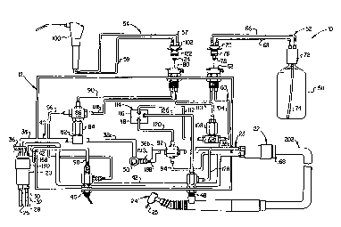
to dental appliances is in~ t~d generally by the reference numPr~l 10 in Figures 1 and 2.
A sterili7~hle portable control box 12 in Figure 1 has a box 14 having an open top which is
closed by cover 16 which is removably f~tPn~ with f~ctenPrs 18. Box 14 has a series of
vent openings 15 in the rear wall to permit egress of steam or gas for stPrili7~ticn.
FYtt~n~ing from the left hand side of control box 12 is an air supply colLneclor for p.es~u~ ;7Yl t
O~latillg air generally de-cign~tPd by ~e reference numPr~l 20. CQnnectQr 20 should be
understood as a convention~l standard CO~ O~ having lines which lead to the master dental
control unit, where the air ~lCSsulc is mod~ t~ by a foot rheostat (not shown) that is
operable by the dentist and is available as standard equipment at most dental opel~ g
~ WO 94/06366 2 1 ~ 4 4 3 ~ PCI /US93/08203
~ .- . ,.
st~tion~. F. tPn-lin~ from the right hand side of control box 12 is a conn~tQr similar to
conn~PctQr 20, generally described by reference nllmer~l 22. Conne~tor 22 is in fluid
co."",~ ic~tinn in a ll,amlcr to be described, with tubing br~n~hes leading in part from
colme~tor 20. C~onnPctc-r 22 is in fact a dental appliance fifflng for det~h~hly P.n~ging a
S dental appliance 24 in Figure 2, shown to be a dental handpiece. A fitting 80 (Figure 2) for
another dental appliance, namely dental syringe 100 is mounted in the rear wall of box 12
with air and sterile water connPcffon~ through tubing h~rnP~s 54 shown in Figure 1.
Air supply conne~;tor 20 has a main air supply branch 26 and an air return tube
28. The tubing h~rne~ of connector 20 also incl~ldes a chip air tube 30 and a water supply
10 tube 32. However, for purposes of the invention, chip air tube 30 communi~tes through
connector 20 with eYh~-ust tube 34 and water supply tube 32 comm~-nic~tes through conneclor
20 with eYh~--st tube 36 which are shown prim~rily for illustration of the fact that the chip
air and water supply through the con~e~.l;on~l tubing h~rn~ are not employed. Chip air and
water would preferably be shut off back at the master dental control unit so that only
15 ~lc~ ed opel~ting air is supplied to the control box through air supply connector 20.
Operating air from supply tube 26 is supplied through conneclor 20 to a main
branch tube 38 of an ;nte.rn~l air supply network referred to generally by the reference
numeral 40. Tnt~rn~l air supply network 40 incl~ldes all the air passageways and connecting
fittings that are intPrn~l to box 12. Main air supply tube 38 is continued by seg...ç~.t~ to be
further described, that lead in fluid comml-nication through collnp~tor 22, h~rnPss 202 and
nltim~t~P.ly to drive the turbine of dental handpiece 24. The drive air from handpiece 24 is
~c~Lull-ed ll~ugll another tube in h~rnPss 202 through connector 22 and return air branch 42
in fluid comm-~nic~tion with connector 20. Return air branch tube 42, a part of intern~l air
supply network 40, is in fluid commlmic~tion with air return tube 28 through conn~tor 20.
The front panel of the control box incllldes an adjustable needle valve 48 and vent
control switch 46. Vent tube 98 is provided to selectively vent a portion of the air from air
supply network 40 in cooperation with control switch 46. This allows, after venting, the
removal of the tube fittings 102 and 70 and the cap 72 of the water supply bottle. The top
cover incll~(lçs an off/on air foot control switch 50. FYten-iing from the back panel of control
box 12 is a tubing h~rn~ss for a ste~ile water supply bottle generally de~ign~t~ 58 and a
tubing h~rnP~ for another dental appliance generally design~tYl by the reference numeral 54.
FYtPn~ling from dental appliance fitting 22 is a tubing h~rn~ss for dental appliance 24
generally dç~ign~ted 202.
wo 94/06366 PCr/us93/08203 ~
2 ~ 3 ~
Figure 2 shows a plan view of the system with cover 16 of box 12 removed. At
the heart of the system is a se~ ely stçrili7~ble water supply bottle 58 which is fluidly
coupled with an intprn~l water supply network 60 in the control box through water supply
fitting 62. TntPm~l water supply network 60 incl~ldçs all the water passageways and
5 conllP~ fittings that are inttorn~l to box 12. Water supply fitting 62 is mounted in the rear
panel of the control box. Tubing harness 52 delivers water and air to water supply fifflng
62 through a water supply tube 66 and an air supply tube 68. An end portion of tubing
harness 52 has a det~h~hle connector 70. An opposite end portion of h~mPs~ 52 has a
removable cap 72 for sterile water bottle 58. Water supply tube 66 is fluidly coupled with
10 depending entry tube 74 eYt~?n~ling to the bottom of bottle 58 through which water is
delivered to tube 66 when the water bottle is ~le~iul ;7çd by opeld~ g air by means of tube
68. Connector 70 has "O" rings 76,78 in s~r~llply defined portions which seal against
intern~l portions of water supply fitting 62 and cooperate therewith to fluidly co.. ~ c~tP
air through tubing 68 and water through tubing 66 in a quick connect and disconnect fitting.
Mounted in the rear wall panel of box 12 ~longsi~e fitting 62 is an j~lçntic~l fitting 80 for
another dental appliance. Thus it may be seen that bottle 58 and h~mPs$ 52 are in fluid
co - ~ ic~tion~ through det~ch~hle connector 62,70, with intPrn~l fluid supply network 60
in the control box, in order to supply sterile water from bottle 58 through tube 66 in response
to Op~d~ g air ple~ e that may be supplied through air supply tube 68 through a
cQnn~cticn with air supply network 40.
TntPrn~l air supply network 40 has a main air supply tube 38 in fluid
commlmic~ti()rl with conn~ctor 22 through main air tube sections 38a, 38b, and 38c. Tubing
38,38a aré conne~ted through tee 82 having one-way flow valve 84 connçcted thereto for
passage of air into four-way junction 86. Junction 86 has a first secondary branch tube 88
through which o~e~ E air from tube 38 passes into water supply fitting 62. When tubing
harness 52 is fluidly coupled with water supply fitting 62, the air from branch 88 passes
through air supply tube 68 and cap 72 to pre~u.;7e the water in bottle 58 so that it can be
supplied to intern~l water supply network 60 through collection tube 74 ~ ugh tube 66 in
harness 52.
Junction 86 also has connected thereto a second secondary branch tube 90 which
at the opposite end is connected to fitting 80 for the supply of o~l~ting air to another dental
appliance. ~imlllt~nP~usly, main drive air is supplied through tubing 38a, switch 50, tube
38b, tube 38c, conn~tor 22 and tubing h~rn~ss 202 to supply drive air to dental h~n-lpieGe
wo 94/06366 ~ 1 4 ~ ~ ~ 9 PCr/USs3/08203
24. One end of main air supply tubes 38b and 38c is collnected to ~l-o!~ four-way junction
92 for passage of drive air the~cl~lruugh. Junction 92 has a chip air branch 94 in fluid
comm-lnir~tion with dental h~n~lpiece 24 through conn~^ctor 22 and tubing h~rne~ 202. Chip
air is supplied in order to blow away debris caused by drill burr 25.
Tnt.-rn~l a r supply ne~wulk 40 incl~ldes a selective means for venting ~lc~
o~ldting air from sterile water bottle 58 so that o~eldting pl~aa.llc can be lGllwv~d from the
bottle as desired for removal of cap 72 and the fittings 102 and 70. This comprises a vent
tube 96 fluidly coupled between junction 86 and toggle switch 46 to eYh~ust vent tube 98
which leads outside the control box to atmosphere. Junction 86 is connected to the main air
supply through the one-way flow valve 84. Valve 84 is adapted to permit air flow to the
junction but retain air plcS~uf~ in the junction and first and second secon-l~ry air br~nch~s
in order to keep the water bottle 58 plc~ ~ ;7e~ with residual preSa~llC after the supply of
o~cl~ling air to the control bo~c has been il~lellu~ed. By opening toggle switch 46 between
vent tube 96 and eYh~ust vent tube 98, residual plCSaUl'C can be relieved to de~le~c.l. ;7~ the
sterile water bottle 58 as desired. Ret~ine l prCSaUl~ will be vented ~imlll~ ~usly from
dental syringe 100 which is connecte~ through tubing harness 54 by means of a quick
connPct r 102 and fitting 80. This has the advantage of y~."~;ll.~lg the dispensing of an
ounce or two of sterile water from bottle 58 through dental syringe 100 at the completion of
a dental operation even after the main air supply at tube 38 has been shut off.
~2~t -rnin~ now to inttorn~l water supply network 60, it will be noticed that all the
sterile water is supplied through tube 104 connecte~ between water supply fitting 62 and tee
106. Branch tube 112 leading from tee 106 is in fluid co,,,,,,~ ic~tion with a normally closed
air operated pilot valve 114 having a water chamber 116 and an air chamber 118 which is
activated or opened by depression of a diaphragm in air chamber 118. The diaphragm
de~l~;sses a valve that controls the flow of sterile water from the sterili7~171e water bottle
through the pilot valve. Air is supplied to pilot valve 114 by means of branch tube 120
leading directly from junction 92. Air to junction 92 and branch tube 120 is selectively
controlled by air control switch 50. Switch 50 ~imlllt~n~ously controls the flow of air in the
main drive air tube 38a, branch tube 120 and tube 94. This st~rili7~hle air actuated pilot
valve 114 can be oblained from ~merie~n Dental Acce~o,;es, Inc. (ADI) of Newberg,
Oregon, and utilizes a VITONm diaphragm.
Sterile water is supplied to dental syringe 100 via tee 106, one-way flow valve 108
and syringe branch 110 in fluid co-mmllnic~tion with connector 80. Conl-~;lor 80 is a quick-
.
wo 94/06366 2 ~ ~ 4 ~ ~ Pcr/uss3/o82o3 ~
coi~n~t and ~ col~n~l fitting which engages connp~lQr 102 having "O" rings 122,124 which
se~ the air and water from branch tubes 90,110 so that the water suppIied from tube 110
through connect~r 80 and connp-ctor 102 is in fluid commllnic~hon with syringe 100 tl,r~ugll
tube 57 leading to the syringe. Air from second second~ry branch 90 is in fluid
comml~ni~ti~n through connp~tor 80 and connPctor 102 with syringe 100 through tube 59
leading to the syringe. Water supply tube 110 may be referred to as the syringe branch and
second secondary branch 90 may be referred to as the syringe air branch. One-way flow
valve 108 connP,ctPcl to tee 106 and syringe branch 110 is adapted to ~vent reverse flow
from syringe 100 so that intPrn~l water supply network 60 cannot be con~".in~tP,d by
backflow from the dental syringe. The flow is always in one direction under p.~s~ule and
nothing can enter the sterile water network by backflow through one-way flow valve 108.
-Finally, water çh~mher 116 of pilot valve 114 has a coolant branch 126 in fluidcomml-ni~tion with needle valve 48 which has an outlet leading to coolant tube 128.
Coolant tube 128 is in fluid co."r"~"~ tion with connP,ctor 22, h~rnP~ 202 and dental
h~ndpiçce 24 in order to supply sterile cooling water in the vicinity of a ~rinrling ~tt~.hm~nt
25 on the dental h~ndpi~pce in order to cool the work area being opeldl~d on. The needle
valve is used to adjust the flow of coolant so that a s-lffi~iPntly fine m-ist or a spray is
provided to the work area, which is always in the vicinity of grin-1ing ~tt~hmPnt 25.
Figure 3 shows the details of connectors 20 and 22 which for collveniçnce will be
~i~cus~P,d with respect to connector 20. Sleeve 130 has a threaded upper portion 132 and a
reduced ~ mp~ter lower portion 134 with a ledge 136 sG~hd~ g the two. Sli~lingly fitted into
sleeve 130 is a body 138 having a rim 140 which rests on ledge 136 in assembly. The lower
end of body 138 has barbed tube connectors 142,144,146,148 with centr~li7pA opening~,
PYten-ling axially from body 138. The openings extend a~cially through the length of body
138 and lç~ ll . . n~e l~s~ iv~ly as openings 150,152,154,156 in the upper face of body 138.
Rim 140 and the upper ll~.s~ e face of body 138 define a sealing surface for a gasket 158
having lt;~ec~ive openings 160,162,164,168 which are aligned with and seal openings
150,152,154,156 when gasket 158 is assembled against the sealing s~ re A threaded end
connector 168 for a tubing h~ s 202 has hollow stems 170,172,174,176 which les~ec~ ely
align with and pass through openings 160,162,164,166 of gasket 158 and openings
150,152,154,156 of body 138.
When sleeve 130 is slipped over body 138 until rim 140 rests on ledge 136, it may
be rotated relative to body 138, gasket 158 and threaded end connector 168 which are drawn
1--wo 94/06366 ' 2 1 ~ 4 4 ~ 9 ~ Pcr/uss3/08203
11
logelheL with the stems in the respective openings. When the threads are engaged to pull the
lower face of connector 168 against the gasket and the gasket 158 against the upper face of
body 138, tightening the sleeve by further rotation se~lingly secures the end conl-eclor and
body to form leak-proof passages for air and water. The leak-proof passages may be
S continue~l Ihlougll threaded end connector 168 to ~ ...h-~P in ~ ecLive tubing barbs for
~tt~chm~,nt of a tubing h~rn~ 202 which may be arranged within a pr~l~;live sheath 178.
Respeclive tubing barbs 180,182,184,186 are aligned with stems 170,172,174,176.
The output end of conn~lor 20 is in fluid cGlllllllll~;c~tion through tube barbs180,182,184,186 with about a 3 foot section of st~rili7~ble ch~o~thed tubing h~rness 202
10 shown in Figure 5. The other end of this section is sep~ted into four individual tube ends
by severing qu~fl~nt~ through cross-shaped hollow 204. Since the invention does not use
co,.~ent;on~l c-hip air and coolant water coming from tubes 30,32 the split off tubes
cQnl~h~ opel~ings 198,200 can be directed into eYh~l-st tubes 34,36 or plugged off on the
input side. The split off tube portion co~ ining ope,~tillg air opening 194 is preferably
15 ~hP~th~ from the short distance from the split to the barb connectio~ at 82 in a manner
similar to Figure 8. Return air tube 196 is .~imil~rly ~h~th~ for a short ~ t~nce and then
is connP,cted to a str~ight through tube barb which is then conl-çcled to return air line 92 for
reasons of economy as will be explained later. The bulk of all the tubes within the control
box can be made of a less eYpen~ive autoclavable m~tto,ri~l The straight through tube barbs
20 are not shown but are merely opposed barbs with an opening through the micldle. In the case
of connector 22, tube barb 184 is connecte~l to the main O~i1ti.~g air tube delivering drive
air to the dental h~nrlri~ce 24 through tubing h~rn~s~ 202 and tube barb 186 is connected to
the return air tube coming from the dental h~ndpiece 24 through tubing h~rnPss 202.
It is ;..-pf ,1t;ve that fluid from the coolant spray opening in the dental h~ndpi~e
be controlled by means which permit coolant to flow, as adjusted by the needle valve, when
main drive air is being supplied to the dental h~ndpiece and to shut off when drive air is shut
off. At the same time, the control means for coolant fluid must not permit backflow into the
sterile water supply in intçm~l water supply network 60. Both of these funcdons are
provided by pilot valve 114, switch 50 and/or the foot control that starts and stops the flow
ples~u.;7~d o~ ;ng air in tube 38 through connector 20 and air supply tube 26 to operate
the dental h~ndriece.
Once tube 38 is pl~ ;7ed, air flows lhlougll one way flow valve 84 into juncdon
86 and pl~-S.~ S the air lines leading to bo~tle 58 and syringe 100 as long as toggle switch
wo 94/06366 - Pcr/uss3/o82o3 ~
3 ~
12
46 is closed. Operating air plcs~ c is retained in this part of the air supply network even
if the supply to tube 38 is shut off and the p~csau~e leaked to atmosphere. As far as the
dental h~n~lp;ece is conrPrn~d, zero opeldlillg plcsaure can also result from closing of switch
50 even if there is still pîe~a~llc in tube 38,38a. The retained Opeldtillg plCSallle means that
5 sterile water in pilot valve water chamber 116 remains under posiLive pf~SSU~ even when
the o~eldLiilg air supply is cut off by either not de~ iaaing the foot rh~ost~t pedal or by
closing foot switch 50. Without activation air presaure applied through tube 120 to air
chamber 118, the valve in water chamber 116 stops the flow of sterile water. Rec~u~e the
water supply in tube 112 is always under plCSaUl~ there is no backflow into the sterile water
10 supply.
Operating air p~aaUrC in junction 92 or absence thereof becomes the dete Ill;ni~g
factor for operation of dental handpiece 24. When o~ dting air is supplied to junction 92,
it ~imlllt~n~ously flows through pilot branch 120 to air ch~mber 118 of valve 114. Valve 114
is a norm~lly closed air activated water relay valve which isolates the air and water supply
15 nelwc~ from each other. Air pres~ule in pilot branch 120 deplesses a diaphragm in air
chamber 118 which in turn dep~sses a valve in water chamber 116 which allows water to
flow from tube 112 to 126 and plcc~ul;~ed sterile coolant fluid is supplied to dental
handpiece 24 simul~i-toously with drive air pressure through tube 38c. When a col-venl;on~l
foot pedal rh~ost~t con~ P4 to the master dental control unit is depl. as~d, drive air is
20 released which turns the turbine in the dental handpiece 24 and drives the drill burr. Sterile
coolant m-ist is ~imlllt~neously e~pell~d from the vicinity of drill burr 25. When the foot
pedal rh~o5t~t on the master dental control unit is not depressed, the drill is stopped and the
flow of coolant mist and chip air are also stopped. If the ope,~ting air p~SaU~e at junction
92 is shut off, as by closing switch 50, the ~l~ saule in pilot branch 120 is reduced to
25 atmospheric and the supply of coolant to the handpiece ceases becau3e the air is no longer
de~iessillg the diaphragm in the air chamber 118 and so the diaphragm is no longer opening
the spring loaded valve in the water chamber. This also keeps the rest of the sterile water
system ple~u~ in air activated pilot valve 114. Thus, handpiece 24 is ~imnlt~n~ously
supplied with Op~ g air, sterile water and chip air or with nothing, depending on the
30 pfe;~a~lre status at junction 92. The pilot valve is a control means in fluid c~s"..~ ic~ion
with the O~.aLil~g air supply to the dental h~n~piece so that air and sterile coolant water are
bo~ either on or off.
Wo 94/06366 ~ ~ 4 ~ 4 3 9 Pcr/US93/08203
13
In operation, the emph~cic is on a compact unit which is easily m~nu~lly portable,
which will dil~clly connP~t to an inct~llP~ dental unit which all dpntictc utilize, which has a
sep~dlely sterili7~hle water supply which holds sllffic;~nt sterile fluid for a typical dental
oper~tion, a sep~ cly stPrili7~hle dental h~ntlpiece and tubing h~rnesc, and a s~ ilttoly
stP~ili7~ble dental syringe and tubing h~rnPcc. The control box is only about 15.2 cm (6")
long, 8.9 cm (3 1/2") wide and 6.4 cm (2 1/2") high. The control box also has vent slots
in the back of the box to allow st~rili7inP steam or other sterili7ing vapors to enter in and
around the air and water tube nelwolh, during st~rili7~tion cycles.
A particular advantage is provided by threaded end connec~ur 168 and the
associated parts shown in Figure 3 which enable control box 12 to be utilized with
cûllvenl;on~l sleeve 130 and body 138 which are convention~l connectionc for a dental
h~ndpiece illllc~t~ as c4nnP~Ior 20 in Figure 1. A similar conneclor 22 is used to connect
and ~licco~ e~il the tubing h~rnPcc of a dental handpiece 24 from control box 12. ~n~1piPce
24 is sep~.i.tPly stçrili7~ble. Dental syringe 100 and water bottle 58 are s~p~ ~t~ly
sterili7~hle and co~ t~ to control box 12 with quick conn~l fittin~c. It is ~nticir~tPA that
the tees and junctions will be made with sterili7~hle electroless nickel plated brass or st~inlecs
steel, as will the quick c~nn~l fittings 80,102, and 62,70.
In order to obtain an a~alus which is stPrili7~hle in an autoclave, m~tPri~lc must
be sPl~ted with care. Aulùclaving means exposing the control box, h~ndpi~e, syringe, and
water bottle and their ~c~:-led tubing h~lllfc~es to steam of at least 121- C (250 F) for
at least 15 minlltes at 1.12 Kg/mm (15 psi). Standard dental tubing and fittings will not
with~t~nd these severe con~itiol-~ which are n~e~si~ y to protect against possible
cont~minatiQn by b~t~ri~l or viral agents. The main air drive tubes 38,38a,38b,38c and the
return air tube 42 have a lumen of .32 cm (1/8"). Tee 82, switch 50, and pilot junction 92
have barbed tubing conn~u. ~ which are sized to se~lingly accept tube with a lumen of about
.32 cm (1/8"). For ~ ~'e, the end of tubing 38b is cut away at 188 to show a barbed
com~ec~ion 190 to switch 50. These tubes are also fitted with crimped metal clamps to hold
them in place.
The rçm~ind~r of the air and water tubes have a lumen of a~ im~tely .16 cm
(1/16") and an outside ~ e~ of a~ro~ ly .48 cm (3/16") and they are connected tothe l~sp~iLive fitting tees, junctinn~ and pilot valve 114. These smaller di~meter tubes are
c~ nn~~ to the fittings and eonn~l~ with suitably sized barbed com ec~ol~ as illby the wl;~vvay portions of tubes 96 and 98 where they are conn~led to tûggle switch 46.
W O 94/06366 ~ 3 9 PC~r/US93/08203
All of these barbed cQI7~ n~ have crimped metal clamps over the tubes which are
ayyLoplia~ly sized to hold the tubes and barbed connections together. Figure 4 shows a
collve~.lioni l 4-hole tubing harness 192 used to inl~.:onnect the convention~ 4-hole
com~e~;Lions of a dental h~-n~p:-ce and the tubing harness leading from the foot control which
supplies operating air and water, chip air and returns used air. This tubing h~-rness is usually
extruded as one piece in the shape shown. It has openings 194,196,198,200 les~ ively for
oyeldting air, return air, cooling water and chip air. However, the convention~l plastic will
not with~t~n~ aulocla~/ing without mPlting or otherwise deteriorating.
Figure 5 shows a pL~rc led form of 4-hole tubing harness 202 in which the body
203 is extruded from ilicone rubber which will with~t~nd autoclaving repe~l~lly and
preferably has a "Shore" hardness on the "A" scale of about 60 or higher. It has the same
openings ~lecign~ted 194,196,198,200 as did the conve~.t;on~l 4-hole h~rn~s~. This is a
relatively soft, very flto~ihle m~t~ri~l Body 203 has a confluent outer wall that is thicker
than the molded in tubes of conn?~l;on~ h~rn~ 192. An outer wall of at least .20 cm (.080)
inches is pl~r~led in order to have a ratio of burst/oy~ ~ng ylGs;~ulc of about 4 to 1 at
about 2.8 Kg/mm (40 psi) which is obtained with the aid of the adjacently placed ~imil~rly
æ~---;7ed intern~l tube walls of tubes 194,196,198,200 but mainly from the eyr~n~e~
tubing cover 206.
Figure 6 shows the cross section of special tubing harness 202. The sp~ing of
openings 194,196,198,200 must be the same as Figure 4 so that the tubing harness will
retrofit coll~e~,t;o~l 4-hole co~ o.ti as must the entire width of tubing h~rn~ 202.
Re~ e the ylc;ÇClled .~ilicone rubber is not as resistant to int~rn~l yl.s~ulc as the
convention~l m~t~ri~l, a special shape is extruded which is further suyycsl~ed against bursting
by the ~r~ntle~ heat shrunk TEFLON~ covering of sheath 206. Preferably the openings
have a slightly smaller ~ .,.P~r than the lumen of the large (.32 cm) (1/8") and small (.16
cm) (1/16") tubes so that the h~rness will have good resilient retention on the connector
tubing barbs to hold it in place. Also, the smaller lumens can be utiliæd due to the natural
l~lmPn~l eYr~n~ion seen with ~ o~P when yle~ul~ is applied int~rn~lly. These smaller
holes also make the ~ ~ne tube 203 smaller in width so that the T~LON~ sheath 206 can
be placed over tube 203 and still have a tubing harness 202 narrow enough in width to
retrofit conv~nlional dental e4uiplllent~
TntPrn~l hollow space 204 is formed roughly in the shape of a cross with a vertical
stem and lateral arms of a width sPkP~ted to accommodate some e~r~n~ion caused by intprn~l
wo 94/06366 ~ 1 ~ 4 ~ 31~ . - Pcr/uss3/o82o3
`e in openings 194-200, farilit~te insertion of tubing barbs and to allow splitting apart
of the individual tubes. The gap in space 204 and the thicknPss of the intPrn~l walls of the
tubes is selected to resist the desired pl~ule. In an eypmpl~ry arrangement, the intprn~l
wall 208 of the smaller tubes having opPnings 198,200 is about .08 cm (.03) inches and
intPrn~l wall 210 of the larger tubes having openings 194,196 is about .127 cm (.05) inches
with a gap bel~een them of about .02 cm (.008) inches. Thus when the tubes 194-200 are
subjected to intP.rn~ es;~uçe~ they can expand slightly and provide int~rn~l su~2oll to each
other without bursting. The hollow "cross" 204 makes it easy to sep~e the end of body
203 into four individual irregular shaped tubes for co~ ~!ion to individual tube barbs. This
feature ~llllil~ a short three or four inch section of tubing h~rness 202 to be used at the
place in~ t~ as 23 in Figure 2 where one end is connlo-cted to colmeclol 22. Theindividual lines 38c,94,128 and 46 can have a section cut out and connected to the individual
tubes split away from the end of body 203 along the arms of the "cross". The sheath
covered ends of the re~ ve tubes are connected to the rem~inder of tubes 38c,94,128,46
by means of straight through tube barb conn~tors (not shown). This ~erll,it~ a less
expensive tube m~tPri~1 to be used within the control box as will be explained below.
Outer sheath 206 is formed from n~ d FEP heat shrunk l~LON~ tubing,
preferably having about .05 cm (.02) inch wall thickness. Equal length ~ ;ng opposing
cuts 214 through both walls are perpendicular to the length and parallel to the width. The
tube sheath will be slightly larger than the circumference of body 203 so as to slide over it
lengthwise. Each cut is preferably about 3 millimeters from the previous OppOSiilg cut
leaving about 2.5 mill;...~ of uncut n~ ~ width. The completed sheath is unfl~tt~n~d
and slid over the entire length of body 203 wher~upoll it is stretched lengthwise to open a
regular pattern of gaps 216 and bands 218 so that there is about 1-1.5 millimPt~rs of space
25 at the widest aspect of the o~slng cuts in the l:EP TEFLON~ tubing. This assembly is
subjected to dry heat of at least 177- C (350 F) for enough time (2-3 .-.i~-ules) to allow the
FEP tubing to shrink tightly against body 203. Appropriately sized elrp~nd~hle FEP
TEFLON~ sheaths are used over the irregular shaped individual tubes sepalaled from an end
of body 203 in the same manner as Figure 8 to provide short ~rts~ul~; resistant connections
30 to the st-~ight through tube barbs preferably used inside the col-fin~os of the control box 12.
Figure 8 shows the same construction as Figure 5 except that an eYr~nd~hle sheath or cover
206 has been in.~t~llPcl in the same ",amlel as described above to p~elll bursting of a
wo 94/06366 2 ~ ~ 4 ~ ~ ~ Pcr/US93/08203 ~
circular shaped ~ilisonto rubber tube 220. This makes a repeatedly autoclavable tube that can
be used between co~ ;onC if desired.
A particular advantage for the special construction of the tubing h~rn~s~ of Figure
S and the tube of Figure 8 is that it p~ the tubing to be easily and flexibly bent without
S ~ffecting its ability to retain int~rn~l pl~Ul~. This is particularly true where sharp bends
are ~ uilc;d and to permit the dental h~ndFiece to be moved around in use. Where straight
or nearly str~ight section~ of tube are employed without bending, a solid uncut shrink fit FEP
TEFLON~ sheath can be used. The silicone tubing can be obtained from New Age
Industries of Willow Grove, PA, and the FEP thermally reducible TEFLON0 sh~thing10 material from Zeus ~ndll~tri~l Products of Orangeburg, SC. The FEP TEFLON~ resin used
to make the shrink fit sheath is nnrm~lly made from DuPont FEP100 or FEP160 grade
lluçoc~bon copolymer resin. The p~pe.lies of typical m~t~ri~l~ are listed on Zeus and
DuPont data sheets sul,lllil~d with this applic~tion. The m~t~ri~l will with~t~nd co~tinllous
use at 204- C (400 F.) and is heat ~hrink~hle at about 177-204- C (350 -400 F).
15 TEFLON0 is a t~de~ k of EI duPont de Nemours, Inc.
It is pfer~. ~hl~ to use a less ey~n~ive but much thicker walled autoclavable tubing
for the intern~l conl-~;on~ of the in~çrn~l water and air supply nt;lwull~ within sterili7~hle
control box 12 and tubing hA...~s 54 and 52 because the ~ilicone rubber and 'l'l~'LONa9
sheath combination is signific~ntly more expensive than other available m~t~ri~l~ and the less
20 expensive m~ttori~l does not have to have the TEFLON~ ~hlo~thing, thus making the
fabrication much easier. PY~...P1~.Y of a tubing m~t~ri~l that will with~t~nd repe~tPA
autoclaving without noticeable det~rioPtion is a ms,teri~l sold under the tr~dem~rk
SANTOPRENF" which is a resilient flexible synthetic rubber supplied by Monsanto Polymer
Products Ch~mir~l Co---pany and fabricated by Hudson Extruders, Inc. of Hudson, Ohio.
25 It has the desirable high (e~ e resi~t~nce necess~y to with~t~ncl typical autoclaving
le-llyel~lul~ s and is al)pluved by the U.S. Food and Drug ~Atlmini.~ tion (FDA).
In the dental art tubing with a lumen of .32 cm (1/8") has a .64 cm (1/4") outside
meter which means the wall is only .16 cm (1/16") thick. If it is desired to have an
~cl~ting plG:~iUlC of 2.1-2.5 Kg/mm (30-35) psig which is only 20% of burst ~lC~-.ll'C
30 ~safety factor of five), it will be n~ to increase the wall thickne~ of the main air drive
and return tubes made of the SANTOPREN~ m~teri~l to .32 cm (1/8") thick with a .95 cm
(3/8") outside ~ meter. Although FDA a~?~val of dental water transporting class IV
co.l.~onents is not e~.~enl;~l, it is a de~ hle feature that is ~l~r~ d.
wo 94/06366 ~ 1 4 ~ 4 3 ~ Pcr/us93/08203
Quick fittings 80,102 and 62,70 are a special order item made of electroless nickel
chrome plated brass in the "Twin Tube" design with VITON~ seals from Colder Products
Colllpally of St. Paul, Mil-nf.so!;. VITON~ is a high ~elr,,lmallce synthetic rubber referred
to as a fluorocarbon and sold by the duPont de Nemours CG11~al~Y. This S~YI1lII~LiC rubber,
S VITON0, is utilized due to its superior re~i~t~nce to ch~mic~l attack and its high le..l1)Ç~ l.G
resist~nce allowing it to be r~ledly autoclaved.
Valves and switches 46,48,84,50,114,48 and 108 may be obtained with the same
above-mentioned VITON0 seals and "O" rings from American Dental Accessolies, Inc.
(ADI) of Newberg, Oregon. All standard plastic parts like push button 50 and toggle switch
10 46 can be ih,~t~llanged with metal co.l-pol ents by the same ADI co,.-~ally as special order
items.
It might be m~ntioned that commonly available ~ilicol~e rubbers are suitable for the
seals in the dental appli~nr~s and co~.nP~ and for the air and water tubing. It has good
flexibility, re~ nce and re~i~t~n~R to high autoclaving le...pe.~dtures and is available in FDA
a~pluved form~ tio~ ~
The sterili7~hle water bottle may be glass or preferably a one liter autoclavable
heavy duty plastic bottle which is fabricated from an enh~nced crystalline homopolymer
polyL.lupylene by Nalge Comp~ny, Rochester, New York. It should with~t~n-l a standard
o~e.~ling l~lcs~ule of 3.5 Kg/mm (50 psig) and be able to be repeatedly autoclaved at
temperatures of up to 135- C (275-F) at up to 2.8 Kg/mm (40 psi) for up to one hour and
be made of an FDA a~.uved m~t~ri~l.
The sterili7~hle ail/w~le~ syringe is a special order item due to the fact that all the
rubber gaskets and "O" rings are in~.~hallged wi~h ~ilicone or VITON~. Also, the standard
plastic yellow and blue inserts next to the activation push buttons are repl~cecl with a st~mped
25 i,~ l of "W" and "A" to in-lic~t.o, which button a~tivates the water and which aclivales the
air. This change is due to the fact that the yellow and blue plastic inserts will melt. This
special order item is fabricated and ol l~Linable from Forest Me-lir~l Products of Hillsboro,
Oregon.
The custom male fitting 168 can be m~mlf~ctured at several advanced m~hin~.
shops and can also be m~nllf~tllred by Forest M~iC~l Products of Hillsboro, Oregon. It
has a body 191 and can be fabricated from ~ n~;n~ , electroless nickel plated brass or
st~inless steel. The thread configuration found on body 191 is 0.555-36 UNS-2A with a
minor di~metPr of 1.33-1.35 cm (0.525-.532") and a pinch (1i~m~tçr of 1.36-1.38 cm
W O 94/06366 PC~r/US93/08203 ~
3 ~
18
(0.5370-.5424"). This thread configuration must be long enough to fully engage the standard
Midwest style "4-hole" connF~tol nut 130 utilized to connect the female ~4-hole~ connp~ctor
138 to this above custom fitting male "4-hole" connector. This threaded portion may e~tend
longer than is nP~ry but must be at least .80 cm (0.315"). Four holes are drilled through
body 191 of custom male "4-hole" connP~tor 168 with the hole co~c~onding with 174
having an intPrn~ F~ of appru,~ ly .39 cm (0.153") and the hole coll~,s~onding
with 176 having an intern~ ",~P, of appro~im~tely .47 cm (0.185"). The two upper,
smaller holes collcs~nding with 170 and 172 have intern~ m~pt~prs of a~plo~;m~tçly .12
cm (0.049"). Body 191 has a ~ eler of approxim~tely 1.46 cm (0.577"). The two
smaller, upper holes would have syringe type thin walled st~inlPss steel tubing with an outer
~i~mloter of ap~r~,.i...~ely .12 cm (0.049'l) PYtPn~ling approxim~t~ly .62 cm (0.245") out of
the body 191 and press fit into the above mpntio~ed two upper holes. Tube 176 preferably
has an outer di~metPr of appr~ t~ly .39 cm (0.153") and an inner ~i~mPt~r of
approxim~tely .32 cm (0.125n) with a wall of approxim~t~?ly .036 cm (0.014"). Tube 174
15 preferably has an outer ~ mptpr of a~ro~ y 0.135" and an inner .I;~...e~. of
approximately .32 cm (0.125") and a wall of approximately .013 cm (0.005"). These two
lower tubes should protrude out of body 191 apl~ru,~;..,~t~ly .79 cm (0.310") for tube 176 and
.95 cm (0.375") for tube 174 and press fit into the a~lupfiate holes.
The two upper st~inl~s~ steel tubes 170 and 172 should exactly index into holes
150 and 152 respectively of fitting 138. The two lower, larger st~inlç~ steel tubes 174 and
176 should exactly index into holes 154 and 156 le~ ely of fitting 138. On the reverse
end of body 191, the two upper holes will be larger with the ability to press fit two single
barbed st~inlP~ steel barbs. The two lower holes will be smaller with the ability to press
fit two single barbed st~inlPss steel tubes. Double barbed connectors 192 and 193 found in
cap 72 of water bottle 58 are fabricated of electroless nickel plated brass and can be
purchased from Beswick F.nginP~ring Co., Inc., of Ipswich, MA.