Language selection

Search

Patent 2144553 Summary

Third-party information liability

Some of the information on this Web page has been provided by external sources. The Government of Canada is not responsible for the accuracy, reliability or currency of the information supplied by external sources. Users wishing to rely upon this information should consult directly with the source of the information. Content provided by external sources is not subject to official languages, privacy and accessibility requirements.

Claims and Abstract availability

Any discrepancies in the text and image of the Claims and Abstract are due to differing posting times. Text of the Claims and Abstract are posted:

  • At the time the application is open to public inspection;
  • At the time of issue of the patent (grant).
(12) Patent: (11) CA 2144553
(54) English Title: SEAL SUSTAINING HARDWARE FOR CASKETS
(54) French Title: MATERIEL DE MAINTIEN D'ETANCHEITE POUR JOINT DE CULASSE
Status: Expired and beyond the Period of Reversal
Bibliographic Data
(51) International Patent Classification (IPC):
  • A61G 17/04 (2006.01)
(72) Inventors :
  • ROJDEV, ILIJA (United States of America)
(73) Owners :
  • BATESVILLE SERVICES, INC.
  • BATESVILLE CASKET COMPANY, INC.
(71) Applicants :
  • BATESVILLE SERVICES, INC. (United States of America)
  • BATESVILLE CASKET COMPANY, INC. (United States of America)
(74) Agent: MACRAE & CO.
(74) Associate agent:
(45) Issued: 2005-02-08
(22) Filed Date: 1995-03-14
(41) Open to Public Inspection: 1995-09-15
Examination requested: 2002-02-28
Availability of licence: N/A
Dedicated to the Public: N/A
(25) Language of filing: English

Patent Cooperation Treaty (PCT): No

(30) Application Priority Data:
Application No. Country/Territory Date
212,268 (United States of America) 1994-03-14

Abstracts

English Abstract


Casket hardware comprises a corrosive trim
plate adapted to be secured to an outer surface of a wall
or a casket, an arm adapted to support a casket handlebar
and having a bolt connected thereto, the bolt being
adapted to pass through the plate and the casket wall, a
nut threadably engaging the bolt interior of the casket,
a seal surrounding the bolt between the nut and the inner
surface of the casket wall and a non-corrosive
compressive load carrying member between the casket wall
and the arm for creating tension in the bolt as the nut
is tightened against the seal. When the corrosive trim
plate corrodes and falls away from between the casket
wall and the arm the non-corrosive compressive load
carrying member maintains the bolt in tension thereby
maintaining the seal in compression between the nut and
the casket wall inner surface.


Claims

Note: Claims are shown in the official language in which they were submitted.

-9-
1. ~Casket hardware comprising:
a corrosive trim plate adapted to be secured to
an outer surface of a wall of a casket;
an arm adapted to support a casket handle bar,
said arm having a bolt connected thereto, said bolt being
adapted to pass through said plate and the casket wall;
a nut threadably engaging said bolt interior of
the casket;
a seal surrounding said bolt between said nut
and an inner surface of the casket wall; and
a noncorrosive compressive load carrying member
between the casket wall and said arm for creating tension
in said bolt as said nut is tightened against said seal;
whereby when said corrosive trim plate corrodes
and falls away from between said arm and the casket wall
said noncorrosive compressive load carrying member
maintains said bolt in tension thereby maintaining said
seal in compression between said nut and the casket wall
inner surface.

-10-
2. Casket hardware as in claim 1 wherein:
said arm includes a clevis, said bolt being
secured to said clevis,
said noncorrosive compressive load carrying
member includes a cylinder having first and second ends,
said bolt passing through said cylinder, said cylinder
first end abutting said clevis, said cylinder second end
abutting the casket wall outer surface.
3. Casket hardware as in claim 2 wherein said
cylinder has an inner diameter sized so as to create a
press fit of said cylinder onto said bolt.
4. Casket hardware as in claim 3 wherein said
cylinder has a flange on said second end, said flange
abutting the casket wall outer surface.
5. Casket hardware as in claim 4 wherein said
noncorrosive compressive load carrying member is
fabricated from plastic.

-11-
6. Casket hardware comprising:
A corrosive trim plate adapted to be secured to
an outer surface of a wall of a casket, said plate having
a fastener securement surface and a casket wall facing
surface;
an arm adapted to support a casket handle bar,
said arm having a bolt connected thereto, said bolt being
adapted to pass through said plate and the casket wall;
a nut threadably engaging said bolt interior of
the casket;
a seal surrounding said bolt between said nut
and an inner surface of the casket wall; and
a noncorrosive spacer having first and second
ends disposed between the casket wall and said arm, said
spacer first end abutting said arm and said spacer second
end abutting the casket wall outer surface, said spacer
having a length dimension greater than the distance
between said plate fastener securement and casket wall
facing surfaces;
whereby when said corrosive trim plate corrodes
and falls away from between said arm and the casket wall
said noncorrosive spacer maintains said bolt in tension
thereby maintaining said seal in compression between said
nut and the casket wall inner surface.

-12-
7. Casket hardware as in claim 6 wherein:
said arm includes a clevis, said bolt being
secured to said clevis,
said noncorrosive spacer includes a cylinder
having first and second ends, said bolt passing through
said cylinder, said cylinder first end abutting said
clevis, said cylinder second end abutting the casket wall
outer surface.
8. Casket hardware as in claim 7 wherein said
cylinder has an inner diameter sized so as to create a
press fit of said cylinder onto said bolt.
9. Casket hardware as in claim 8 wherein said
cylinder has a flange on said second end, said flange
abutting the casket wall outer surface.
10. Casket hardware as in claim 9 wherein said
noncorrosive spacer is fabricated of plastic.

-13-
11. ~Casket hardware comprising:
a trim plate adapted to be secured to an outer
surface of a wall of a casket;
a bolt having a load carrying surface on one
end, said bolt being adapted to pass through said plate
and the casket wall;
a nut threadably engaging said bolt interior of
the casket;
a seal surrounding said bolt between said nut
and an inner surface of the casket wall; and
a noncorrosive compressive load carrying member
between the casket wall and said bolt load carrying
surface for creating tension in said bolt as said nut is
tightened against said seal;
whereby should said trim plate corrode and fall
away from between said bolt load carrying surface and the
casket wall said noncorrosive compressive load carrying
member maintains said bolt in tension thereby maintaining
said seal in compression between said nut and the casket
wall inner surface.

-14-
12. ~Casket hardware as in claim 11 wherein said
noncorrosive compressive load carrying member is a
plastic cylinder having a flange on its casket wall end
and an inner diameter sized so as to create a press fit
of said cylinder onto said bolt.

-15-
13. Casket hardware comprising:
a trim plate adapted to be secured to an outer
surface of a wall of a casket, said plate having a
fastener securement surface and a casket wall facing
surface;
a bolt having a load carrying surface on one
end engaged with said plate fastener securement surface,
said bolt being adapted to pass through said plate and
the casket wall;
a nut threadably engaging said bolt interior of
the casket;
a seal surrounding said bolt between said nut
and an inner surface of the casket wall; and
a noncorrosive spacer having first and second
ends disposed between the casket wall and said bolt load
carrying surface, said spacer first end abutting said
bolt load carrying surface and said spacer second end
abutting the casket wall outer surface, said spacer
having a length dimension greater than the distance
between said plate fastener securement and casket wall
facing surfaces;
whereby should said trim plate corrode and fall
away from between said bolt load carrying surface and the
casket wall said noncorrosive spacer maintains said bolt
in tension thereby maintaining said seal in compression
between said nut and the casket wall inner surface.

-16-
14. Casket hardware as in claim 13 wherein said
noncorrosive spacer is a plastic cylinder having a flange
on said second end and an inner diameter sized so as to
create a press fit of said cylinder onto said bolt.

-17-
15. Casket hardware comprising:
a plate adapted to be secured to an outer
surface of a casket wall;
an elongated first portion of a fastener
assembly having a load carrying surface on one end, said
elongated first portion adapted to pass through said
plate and the casket wall;
a second portion of the fastener assembly for
securing said first portion interior of the casket;
a seal surrounding said fastener assembly first
portion between said fastener assembly second portion and
an inner surface of the casket wall; and
a noncorrosive compressive load carrying member
between the casket wall and said fastener assembly first
portion load carrying surface for creating tension in
said fastener assembly first portion as said fastener
assembly second portion is tightened against said seal;
whereby should said plate corrode and fall away
from between said fastener assembly first portion load
carrying surface and the casket wall said noncorrosive
compressive load carrying member maintains said fastener
assembly first portion in tension thereby maintaining
said seal in compression between said fastener assembly
second portion and the casket wall inner surface.

-18-
16. Casket hardware comprising:
a plate adapted to be secured to an outer
surface of a casket wall, said plate having a fastener
securement surface and a casket wall facing surface;
an elongated first portion of a fastener
assembly having a load carrying surface on one end
engaged with said plate securement surface, said
elongated portion adapted to pass through said plate and
the casket wall;
a second portion of the fastener assembly for
securing said first portion interior of the casket;
a seal surrounding said fastener assembly first
portion between said fastener assembly second portion and
an inner surface of the casket wall; and
a noncorrosive spacer having first and second
ends disposed between the casket wall and said fastener
assembly first portion load carrying surface, said spacer
first end abutting said load carrying surface and said
spacer second end abutting the casket wall outer surface,
said spacer having a length dimension greater than the
distance between said plate fastener securement and
casket wall facing surfaces;
whereby should said plate corrode and fall away
from between said fastener assembly first portion load
carrying surface and the casket wall said noncorrosive
spacer maintains said fastener assembly first portion in
tension thereby maintaining said seal in compression

-19-
between said fastener assembly second portion and the
casket wall inner surface.

Description

Note: Descriptions are shown in the official language in which they were submitted.


- 214453
- 1 -
SEAL SUSTAINING HARDWARE FOR CASKETS
FIELD OF THE INVENTION
This invention relates generally to caskets,
and more particularly to hardware for use on metal
caskets which sustains or maintains an effective seal
about the casket wall through holes should the decorative
plate which the hardware mounts to the casket shell
corrode and dissipate.
BACKGROUND OF THE INVENTION
A casket is formed as a deep, hollow metal
shell which is closed by a cap or top. Much effort is
expended to provide assurance that the casket is leak-
tight so that water cannot leak into the casket when the
casket is buried underground. It is also important that
body gases or liquids not leak out of the casket when
disposed in a mausoleum, etc. Special gaskets have been
designed for engagement of the cap with the shell to
prevent leakage around the perimeter of the casket. One
of the final steps in the manufacturing process of the
casket is to pressure test the casket with the lid closed

2144553
- 2 -
to determine whether the casket, before it is shipped, is
indeed leak tight.
The casket hardware presents a potential site
for leakage. Conventionally, holes are drilled through
the walls of the casket shell. Bolts are passed through
these through holes to mount hardware to the shell, the
hardware providing the handles by which the casket is
carried. Washers are inserted over the bolts interior of
the casket, and a nut is threaded onto the bolt for
securing the washer thereon. Sealing mastic is disposed
about the bolt between the washer and the inner surface
of the casket wall. Tightening the nut on the bolt
causes the bolt to compress the trim hardware, sometimes
known as "ear" hardware or an "escutcheon" plate, thereby
creating tension in the bolt, which causes the nut and
washer to compress the sealing mastic to the inner
surface of the casket wall, thus sealing the hole.
The problem associated with this traditional
mounting of hardware to the casket wall and sealing
thereof is that when the ear hardware or escutcheon
plate, commonly fabricated of zinc, corrodes, dissipates
and otherwise falls away from between the casket wall and
the bolt head, the means for creating tension in the bolt
and hence compression in the sealing mastic between the
washer and the casket wall inner surface is eliminated.

2144~~3
- 3 -
Thus, without bolt tension to compress the sealing mastic
between the washer and the casket wall inner surface, the
seal is effectively compromised or lost.
BRIEF DESCRIPTION OF THE INVENTION
It has therefore been an objective of the
present invention to provide hardware for caskets which
sustains or otherwise maintains an effective seal about
the through holes in the casket walls should the trim
plates corrode and fall away from the bolts in the casket
1o wall.
The objective of the present invention has been
attained by providing casket hardware which comprises a
corrosive trim plate adapted to be secured to an outer
surface of the wall of the casket, an arm adapted to
support a casket handlebar, the arm having a bolt
connected thereto, the bolt being adapted to pass through
the plate and the casket wall, a nut threadably engaging
the bolt interior of the casket, a seal surrounding the
bolt between the nut and an inner surface of the casket
wall, and a non-corrosive compressive load carrying
member between the casket wall and the arm for creating
tension in the bolt as the nut is tightened against the
seal. When the corrosive trim plate corrodes and falls
away from between the arm and the casket wall the non-
corrosive compressive load carrying member maintains the

p>
....
2144553
- 4 -
bolt in tension thereby maintaining the seal in
compression between the nut and the casket wall inner
surface thereby sustaining the integrity of the seal.
The arm includes a clevis, with the bolt being
secured to the clevis. The non-corrosive compressive
load carrying member includes a cylinder having first and
second ends. The bolt passes through the cylinder, with
the cylinder first end abutting the clevis, and the
cylinder second end abutting the casket wall outer
surface. The cylinder has a inner diameter sized so as
to create a press fit of the cylinder onto the bolt. The
cylinder has a flange on the second end, with the flange
abutting the casket wall outer surface. The non-
corrosive compressive load carrying member is preferably
fabricated from plastic.
The trim plate includes a fastener securement
surface and a casket wall facing surface. The fastener
securement surface is that surface which is contacted by
the arm clevis when the bolt is inserted through the
plate. The casket wall facing surface is the extrememost
surface of the plate facing the casket wall. To ensure
that the non-corrosive compressive load carrying member
or spacer, and not the trim plate, carries the
compressive load as the nut is tightened on the bolt, the
spacer has a length dimension greater than the distance

2144553
- 5 -
between the plate fastener securement and casket wall
f acing surf aces .
An advantage of the present invention is that
in casket hardware, when the decorative trim plate, or
ear hardware or escutcheon plate, corrodes and falls away
from the hardware bolt, the seal sealing the casket wall
through hole remains intact and is not compromised
thereby.
These and other objects and advantages of the
present invention will become more readily apparent
during the following detailed description taken in
conjunction with the drawings herein in which:
BRIEF DESCRIPTION OF THE DRAWINGS
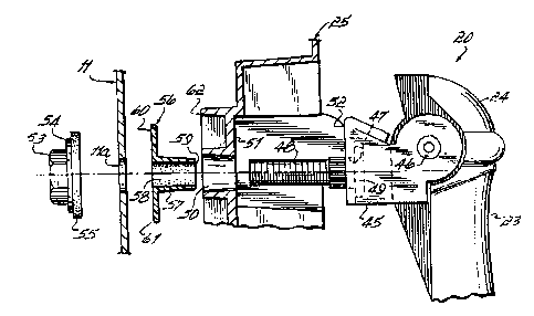
Fig. 1 is a perspective view of a casket
showing its hardware mounted on the shell;
Fig. 2 is an assembled side cross-sectional
view taken along line 2-2 of FIG. 1 illustrating the
mounting hardware of the present invention; and
Fig. 3 is a view similar to Fig. 2 except with
the hardware shown exploded in disassembled form.
DETAILED DESCRIPTION OF THE INVENTION
Referring first to Fig. 1, there is shown a
casket 10 having a sheet metal shell 11 enclosed by cap
12. The cap 12 has a head section 13 and foot section
14. Seals or gaskets (not shown) around the perimeter of
the head section and foot section 12 and 13,

_ 21~455~
- 6 -
respectively, are provided to form a leak-tight joint
between the cap and seal.
The hardware indicated at 20 can take many
forms. The illustrated hardware is merely exemplary. A
handle bar 21 is mounted, at a number of places along its
length, to the free end 22 of an arm 23. The arm 23 is
pivoted at 24 to a wall of the shell 11, and a die-cast
trim plate, otherwise known as an "ear" or "escutcheon"
25, overlies the joint between the arm 23 and the shell
11.
Figs. 2-3 shown the details of the mounting of
a representative arm 23. The arm 23 has a clevis 45
mounted to it by a rivet 46. The clevis has a mounting
hole 47. A bolt 48 having a head 49 on one end is press
fitted into the hole 47 in the clevis 45. Escutcheon 25
has a through hole 50 therethrough for accepting the
shank of bolt 48. The wall of casket shell 11 has a
through hole 11a for accepting the shank of bolt 48.
Escutcheon 25 has a surface 51 which faces the arm 23 and
against which is abutted a forward face 52 of clevis 45
when bolt 48 is inserted through hole 50. For securing
bolt 48 on the interior of the casket there is a nut 53
which threadably engages the bolt 48, and a washer 54 is
disposed between nut 53 and the casket wall. Sealing
mastic 55 surrounds the bolt 48 and is disposed between

2.44553
_ 7 _
the washer 54 and the inner side or surface of the wall
of shell 11.
A non-corrosive, for example plastic, spacer 56
is disposed between the casket shell 11 and the arm 23.
The spacer 56 preferably includes a cylindrical portion
57 which fits in hole 50 of escutcheon 25 and which
includes an inner bore or diameter 58 sized so as to be a
press fit on the shank of bolt 48. One end 59 of the
cylinder 57 abuts the casket wall facing face 52 of the
clevis 45, while the other end 60 which includes a flange
61 thereon abuts the outer surface of the wall of casket
shell 11. The spacer 56 is sized so as to be longer than
the distance between the surface 51 of escutcheon plate
25 and a casket wall facing surface 62 of escutcheon
plate 25, such that when nut 53 is tightened onto bolt 48
spacer 56 carries the compressive load which generates
tension in bolt 48 and hence compression in mastic seal
55 between washer 54 and the wall of shell 11. Thus,
reliance is not made on escutcheon plate 25 as being the
means to generate the tension in bolt 48 upon tightening
of nut 53. Thus, when escutcheon 25 corrodes, dissipates
and otherwise falls away from between the casket shell 11
and the arm 23, the compressive load carrying member, the
non-corrosive spacer 56, remains in place thus ensuring
that bolt 48 remains in tension and that mastic seal 55

__ , _ 21445~~
_8_
remains in compression between seal 54 and shell 11 thus
insuring the integrity of the seal.
Another advantageous feature of spacer 56 is
that it provides a handy means of forming a subassembly
of escutcheon 25, arm 23 and bolt 48, since spacer 56,
press fitted onto the shank of bolt 48 after bolt 48 is
inserted through hole 50 of escutcheon 25, readily holds
the various components together as a single unit. Thus,
spacer 56 serves to speed the manufacturing process by
allowing an assembler to handle a subassembly rather than
many individual pieces.
Those skilled in the art will readily recognize
numerous adaptations and modifications which can be made
to the casket hardware of the present invention and which
result in improved casket hardware, yet all of which will
fall within the spirit and scope of the present invention
as defined by the following claims. Accordingly, the
invention is to be limited only by the scope of the
following claims and their equivalents.
What is claimed is:

Representative Drawing
A single figure which represents the drawing illustrating the invention.
Administrative Status

2024-08-01:As part of the Next Generation Patents (NGP) transition, the Canadian Patents Database (CPD) now contains a more detailed Event History, which replicates the Event Log of our new back-office solution.

Please note that "Inactive:" events refers to events no longer in use in our new back-office solution.

For a clearer understanding of the status of the application/patent presented on this page, the site Disclaimer , as well as the definitions for Patent , Event History , Maintenance Fee  and Payment History  should be consulted.

Event History

Description Date
Time Limit for Reversal Expired 2006-03-14
Letter Sent 2005-03-14
Grant by Issuance 2005-02-08
Inactive: Cover page published 2005-02-07
Inactive: Final fee received 2004-11-23
Pre-grant 2004-11-23
Notice of Allowance is Issued 2004-05-27
Letter Sent 2004-05-27
Notice of Allowance is Issued 2004-05-27
Inactive: Approved for allowance (AFA) 2004-04-01
Amendment Received - Voluntary Amendment 2002-05-01
Letter Sent 2002-03-20
Inactive: Status info is complete as of Log entry date 2002-03-20
Inactive: Application prosecuted on TS as of Log entry date 2002-03-20
All Requirements for Examination Determined Compliant 2002-02-28
Request for Examination Requirements Determined Compliant 2002-02-28
Letter Sent 2000-02-08
Inactive: Multiple transfers 1999-12-29
Application Published (Open to Public Inspection) 1995-09-15

Abandonment History

There is no abandonment history.

Maintenance Fee

The last payment was received on 2003-12-22

Note : If the full payment has not been received on or before the date indicated, a further fee may be required which may be one of the following

  • the reinstatement fee;
  • the late payment fee; or
  • additional fee to reverse deemed expiry.

Patent fees are adjusted on the 1st of January every year. The amounts above are the current amounts if received by December 31 of the current year.
Please refer to the CIPO Patent Fees web page to see all current fee amounts.

Fee History

Fee Type Anniversary Year Due Date Paid Date
MF (application, 3rd anniv.) - standard 03 1998-03-16 1998-03-10
MF (application, 4th anniv.) - standard 04 1999-03-15 1999-02-18
Registration of a document 1999-12-29
MF (application, 5th anniv.) - standard 05 2000-03-14 2000-02-18
MF (application, 6th anniv.) - standard 06 2001-03-14 2000-12-28
MF (application, 7th anniv.) - standard 07 2002-03-14 2002-01-04
Request for examination - standard 2002-02-28
MF (application, 8th anniv.) - standard 08 2003-03-14 2002-12-20
MF (application, 9th anniv.) - standard 09 2004-03-15 2003-12-22
Final fee - standard 2004-11-23
Owners on Record

Note: Records showing the ownership history in alphabetical order.

Current Owners on Record
BATESVILLE SERVICES, INC.
BATESVILLE CASKET COMPANY, INC.
Past Owners on Record
ILIJA ROJDEV
Past Owners that do not appear in the "Owners on Record" listing will appear in other documentation within the application.
Documents

To view selected files, please enter reCAPTCHA code :


To view images, click a link in the Document Description column. To download the documents, select one or more checkboxes in the first column and then click the "Download Selected in PDF format (Zip Archive)" or the "Download Selected as Single PDF" button.

List of published and non-published patent-specific documents on the CPD .

If you have any difficulty accessing content, you can call the Client Service Centre at 1-866-997-1936 or send them an e-mail at CIPO Client Service Centre.


Document
Description 
Date
(yyyy-mm-dd) 
Number of pages   Size of Image (KB) 
Representative drawing 1998-08-11 1 11
Description 1995-03-13 8 252
Abstract 1995-03-13 1 25
Claims 1995-03-13 11 231
Drawings 1995-03-13 1 48
Representative drawing 2004-04-01 1 16
Reminder - Request for Examination 2001-11-14 1 118
Acknowledgement of Request for Examination 2002-03-19 1 180
Commissioner's Notice - Application Found Allowable 2004-05-26 1 161
Maintenance Fee Notice 2005-05-08 1 172
Correspondence 2004-11-22 1 31
Fees 1997-02-24 1 61