Note: Descriptions are shown in the official language in which they were submitted.
214~80~
Background of the Invention
This invention relates to sight glasses, and in
particular, to sight glasses for usè with pressurized vessels,
such as boilers.
Sight glasses are often used in conjunction with
pressure vessels to observe the liquid level in the vessel. A
few designs provide an entry port for probes and sensors used to
control vessel temperature, pressure, etc. Commercially
available sight glasses presently have a single chamber in
communication with the interior of the vessel. This exposes the
glass of the sight glass and the probes to wet steam from the
vessel. In operational use, the hot, wet st am often either
condenses on the glass, or etches the glass permanently, making
it difficult to observe the liquid and probes contained within
the sight glass. The steam also will cause the liquid in the
sight glass to bubble or boil resulting in false readings, both
from the probe and visual observation, as to the true liquid
level in the vessel. The direct contact of the wet steam on the
probes may also result in other false readings. The false
readings make control of the process in which the vessel is
incorporated difficult.
Summary of the Invention
One object of_the present invention is to provide an
improved sight glass assembly for use with a pressure vessel.
WIEI 5432/0689S
214480~
Another object is the provision of such a sight glass
assembly which will reduce the possibility of etching of the
glass during operational use.
Another object is the provision of such a sight glass
assembly which will reduce the possibility of false readings by
instruments placed in the sight glass.
Another object of the present invention is to provide a
sight glass assembly in which wet steam, foam, or bubbles will
not condense on the glass of the sight glass assembly or around
probes and sensors housed in the sight glass assembly.
Another object of the present invention is to produce a
sight glass which reduces the number of seals incorporated in the
sight glass assembly, and hence the possibility of leakage at or
through the sight glass assembly.
Another object of the present invention is the provision
of a sight glass assembly which is economical to produce and easy
to assemble.
These and other objects will become apparent to those
skilled in the art in light of the following disclosure and
accompanying drawings.
Briefly stated, a sight glass assembly is provided which
is securable to a pressure vessel, such as by welding. The sight
glass includes a one-piece body having back, top, bottom, and
front surfaces which together define a chamber. The chamber is
in communication with an interior of the vessel through an
-- 3 --
WIEI 54 32 / 06895
214 180~
opening in the back surface of the body and an opening in the
wall of the vessel. The body front has an opening which is
counter-sunk and receives a glass to close the chamber. A cover
fits over the glass to secure the glass to the body. The sight
glass body is preferably welded to the vessel. Therefore, the
only seals used by the sight glass assembly are gaskets placed on
either side of the glass to form fluid tight seals between the
glass and the body.
A baffle is formed in the chamber to divide the chamber
into a back chamber adjacent the mounting surface and a front
chamber spaced from the mounting surface. A pair of ports are
placed in the baffle to place the front chamber in fluid
communication with the back chamber and the interior of the
vessel. The body has at least one port formed in its walls which
is in communication with the front chamber. The port allows for
the insertion of a sensing device into the front chamber.
The baffle prevents steam, foam, or bubbles from
entering the front chamber. The steam, foam or bubbles condense
against the baffle in the back chamber so that only liquid enters
the front chamber. This enables the sensing devices to sense the
conditions of the vessel more accurately and reduces the
occurence of false signals emitted by the devices when gasses are
allowed to contact the_sensing devices. The baffle also prevents
the hot steam, foam or bubbles from contacting the glass and thus
reduces the etching of the glass.
WIEI 5432/0689S
21~480~
Brief Description of the Drawinqs
FIG. 1 is an exploded top plan view, partly in section,
of a sight glass assembly of the present invention, the sight
glass body being mounted to a pressure vessel;
FIG. 2 is an exploded, side elevational view of the
sight glass assembly;
FIG. 3 is a cross-sectional view of the sight glass
assembly mounted to the vessel, taken along lines 3--3 of FIG. 1,
with a probe being housed in the assembly;
FIG. 4 is a top plan view of a body of the sight glass
with ports of the sight glass body being shown in phantom;
FIGS. 5 and 6 are side elevational views of the two
sides of the body;
FIG. 7 is a front elevational view of the sight glass
assembly;
FIG. 8 is a back plan view of the body;
FIG. 9 is a cross-sectional view of the body taken along
line 9--9 of FIG. 10;
FIG. 10 is a cross-sectional view of the body taken
along line 10--10 of FIG. 4;
FIG. 11 is a cross-sectional view taken along line
11--11 of FIG. 4;
FIG. 12 is a cross-sectional view taken along line
12--12 of FIG. 4;
W}EI 543Z/0689S
21~800
FIG. 13 is a cross-sectional view taken along line
13--13 of FIG. 4;
FIG. 14 is a front plan vièw, partly broken away, of a
cover of the sight glass assembly.
FIG. 15 is a cross-sectional view of the cover taken
along line 15--15 of FIG. 14; and
FIG. 16 is a cross-sectional view of the cover taken
along line 16--16 of FIG. 14.
Description of the Preferred Embodiment
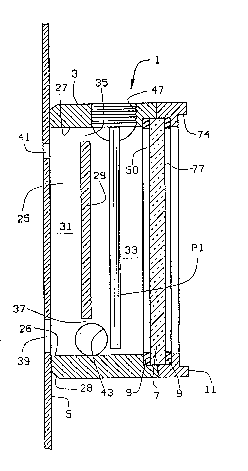
An illustrative embodiment of a sight glass assembly 1
of the present invention is shown in FIGS. 1-3. Assembly 1
includes a sight glass body 3 which is mounted to an outer
surface of a wall 5 of a vessel V, such as a boiler. A glass 7,
surrounded by a pair of gaskets 9, is received in body 3 and is
secured in place by a cover or lid 11. Although the sight glass
1 is described as being mounted to a pressure vessel, it will be
apparent that the sight glass of the present invention may be
used with any vessel.
Body 3 is shown in more detail in FIGS. 4-13. Body 3
has front 13, top 15, bottom 17, sides 19 and 21, and back 23
surfaces, which together define a chamber 25 (FIG. 10). Back
surface 23 is preferably curved to conform to the curvature of
the vessel wall 5 to which the assembly 1 is mounted. The body 3
is physically mounted to vessel 3, by welding, for example. The
back wall 23 has an elongate opening 27 to chamber 25. Opening
WIEI 5432/0689S
2144800
27 is defined by a wall or surface 26. The wall 5 of vessel V
has a port 39 and a port 41 formed therein (FIG. 3). The ports
39 and 41 communicate with the chamber 25. Although gaskets
could be used to form a fluid tight seal between the vessel V and
the sight glass body 3, the form of attachment of the body to the
vessel is such that a gasket is not needed, and therefore is
preferably not provided. This reduces the number of seals needed
by the sight glass assembly 1. The outer surfaces of body 3 are
preferably chamfered, as at 28 (FIGS. 8-10), to define an area of
transition between the back wall 23 and the sides, top, and
bottom of the body 3.
A baffle 29 is formed in chamber 25_forwardly of opening
27 and divides chamber 25 into a back chamber 31 and a front
chamber 33. The baffle has concave, generally semi-circular
front and rear surfaces. (See FIG. 9) An upper port 35 and a
lower port 37 are formed in baffle 29 near the top and bottom,
respectively, of the body to place front chamber 33 in fluid
communication with the interior of vessel V through the back
chamber 31. As seen, ports 35 and 37 are formed to be at the top
and bottom, respectively, of opening 27. Lower port 37 is shown
to be larger than port 35 and preferably has a diameter about
twice that of port 35. Corresponding ports 39 and 41 (FIG. 3)
are formed in vessel wall 5 so that chambers 31 and 33 will be in
fluid communication with the interior of the vessel. Vessel
ports 39 and 41 are shown to be of different sizes, but may be of
WIEI 5432/0689S
21~480~
the same size if desired. The body 3 is preferably molded or
cast, and the baffle is molded or cast in the body when the body
is formed. Baffle 29 could alternatively be a separate piece
which is secured in body 3.
Body 3 is mounted to vessel wall 5 so that back surface
23 surrounds the vessel ports 39 and 41, i.e., ports 39 and 41
are within opening 27 to be surrounded, contained, or enclosed by
opening wall 26. The vessel ports are preferably formed so that
vessel port 39 is axially aligned with body port 37 and vessel
port 41 is axially or vertically offset from body port 35, as
seen in FIG. 3. The offset of vessel port 41 and body port 35
prevents a direct flow of fluid from vessel V to body chamber
33. Because the fluid flowing through vessel port 41 will impact
the baffle 29 prior to entering body chamber 35, the amount of
gas bubbles or foam that enter chamber 35 is reduced.
Sight glass body 3 also includes a drain port 43 formed
in wall 21, a probe port 45 formed in wall 19, and a probe port
47 formed in top 15. As best seen in FIG. 10, all three ports
are in direct communication with forward chamber 33. Drain port
43 is formed at the bottom of the chamber. A drain tube having a
valve may be connected to port 43 so that the assembly 1 can be
drained when desired.
Port 45 is a steam port. Sensing equipment, such as
pressure probes may be placed in communication with the interior
of vessel V through port 45. The pressure probe may be connected
WIEI 5432/06895
2l~4sn~
to appropriate switching devices to control the pressure within
the vessel based on the output from-the pressure probe.
Electronic sensors and test probes Pl are placed in
communication with the interior of vessel V through port 47.
These may include temperature and level probes to monitor the
temperature and level of the fluid within the vessel and sensors
which monitor other desired properties of the fluid in the
vessel. Again, these probes and sensors may be connected to
appropriate control devices to control the desired propertles of
the fluid contained within the vessel.
The body front surface 13 has an opening 50 which is
counter-sunk to define a shoulder 51. Glass_7 is placed in
opening 50 to be seated on shoulder 51. A gasket 9 is preferably
placed between the glass 7 and shoulder 51 to form a fluid tight
seal therebetween. Gasket 9 is preferably shaped to conform to
the dimensions of shoulder 51 so that it does not extend beyond
the shoulder into opening 50 Glass 7 and vessel wall 5 thus
define the front and back walls, respectively, of chamber 25.
Front surface 13 also includes elongate flanges 53 extending
outwardly from side walls 19 and 21. A plurality of bolt holes
55 are formed in each flange.
The sight glass cover 11 is best shown in FIGS. 14-16.
Cover 11 includes a back wall 61 follows the symmetry of flanges
53 of body 3, a front surface 63, top and bottom surfaces 65, and
side surfaces 67. A plurality of bolt holes 69 extend through
WIEI 5432/0689S
- 214~800
cover 11 and are aligned with bolt holes 55 in body flanges 53.
Bolts 71 (FIG. 1) pass through the bolt holes 55 and 69 and
receive nuts 73 to secure the cover 11 to the body 3. Body
flanges bolt holes 55 may be tapped to accept screws, to
eliminate the need for nuts 73. Ribs 74 preferably extend across
front surface 63 at the top and bottom thereof.
An elongate, preferably oval, opening 75 is formed in
cover 11. Opening 75 is counter-bored at 77 to define a shoulder
79. Glass 7 is received within counter-bore 77 to seat against
shoulder 79, as seen in FIGS. 1 and 3 . Another gasket 9, which
conforms in shape to the shape of shoulder 79, is placed between
the glass 7 and shoulder 79 to provide a fluid tight seal or
cushion between the glass and the cover. Gaskets 9 are both
generally oval and are set against the walls of their respective
shoulders and near the periphery of the glass 7. Opening 75 is
approximately the same size as body opening 50.
When sight glass assembly 1 is used with a pressure
vessel, such as a boiler, the steam, foam, bubbles, and water
produced by the boiler enter the assembly 1 through vessel ports
39 and 41. The steam condenses against the baffle 29 in back
chamber 31 and liquid enters the front chamber 33 through port
37. Only condensed fluid (i.e. liquid) enters front chamber 33
and reaches the glass 1 and probe P1. Thus no hot bubbles or
foam which will etch the glass entering the front chamber 33.
Virtually no bubbles or foam reach the front chamber 33. Because
-- 10 --
WIEI 5432/06895
214480~
no bubbles or foam enter the front chamber 33, where the sensing
devices are located, no bubbling of the liquid occurs in the
front chamber. Thus, a true liquid level will be measured by the
probe and visible through the sight glass. Further, because the
liquid is not being affected by bubbles or foam, and because a
true liquid level is being shown, the probes and sensors inserted
through ports 45 and 47 will not produce false signals which
would otherwise be produced if bubbles or foam did reach the
probes. Baffle 29, thus shields the probes from the bubbles or
foam to reduce the possibility of false readings. Better control
of the vessel (i.e. vessel temperature, pressure, etc.), and the
production line in which it is incorporated, is thus achieved.
Variations within the scope of the apended claims will
be apparent to those skilled in the art. The foregoing
description is thus set forth for illustrative purposes only and
is not meant to be limiting.
WIEI 5632/0689S