Language selection

Search

Patent 2144902 Summary

Third-party information liability

Some of the information on this Web page has been provided by external sources. The Government of Canada is not responsible for the accuracy, reliability or currency of the information supplied by external sources. Users wishing to rely upon this information should consult directly with the source of the information. Content provided by external sources is not subject to official languages, privacy and accessibility requirements.

Claims and Abstract availability

Any discrepancies in the text and image of the Claims and Abstract are due to differing posting times. Text of the Claims and Abstract are posted:

  • At the time the application is open to public inspection;
  • At the time of issue of the patent (grant).
(12) Patent Application: (11) CA 2144902
(54) English Title: DRIP/SPILL GUARD DEVICE
(54) French Title: DISPOSITIF ANTI-GOUTTES POUR CONTENANT DE PEINTURE
Status: Deemed Abandoned and Beyond the Period of Reinstatement - Pending Response to Notice of Disregarded Communication
Bibliographic Data
Abstracts

English Abstract


A drip/spill guard device for catching paint drips and spills,
usable with any conventionally sized paint can. It consists of
four principle parts: (1) a circular base section; (2) a
containment flange; (3) a containment lip; and (4) a
circumferential pressure clip connected to a retaining wall. The
upper abutment surface of the base section of this device hosts a
protruding circumferential pressure clip which detachably secures
the device to the bottom rim of any conventionally sized paint
can. A containment flange, which features a moulded grip, is
attached circumferentially to this base section and extends
upwardly and outwardly at a prescribed angle to a prescribed
height so as to form a containment chamber which serves to
receive and retain spilled paint. Attached to the edge of the
flange, corresponding to the pouring side of the paint can, is a
containment lip which serves to prevent already contained paint
from spilling out of the device when the paint can is tilted to
pour paint.


Claims

Note: Claims are shown in the official language in which they were submitted.

The embodiments of the invention in which an exclusive property
or privilege is claimed are defined as follows:
A. In the case of an apparatus -
1. A drip/spill guard device, being stackable and usable with
any conventionally sized paint can, comprising:
(a) a base section which generally contours to the base of any
conventionally sized paint can and is larger in surface area
than said paint can.
(b) a containment flange which attaches circumferentially to
the edge of the base section and which extends upwardly and
outwardly at a prescribed angle and to a prescribed height
with respect to the base section, and which forms a
containment chamber with the upper abutment surface of said
base section.
(c) a containment lip which attaches to a portion of the edge
of the containment flange for the purpose of retaining already
contained paint once the device is tilted.
(d) a circumferential retaining wall which protrudes from the
base section and serves to prevent the bottom of the paint can
from becoming soiled with paint.
(e) a circumferential pressure clip which protrudes from the
retaining wall and allows the device to be detachably secured
to the bottom rim of a paint can.
(f) a pouring grip which is recessed into the flange opposite
the pouring side of the paint can, thus providing the user
with a way of gripping the device so that the user's hands
need not soil the base of the device.
(g) a tab, for purpose of displaying said device, which
protrudes from the edge of the containment flang corresponding
to the moulded pouring grip.
2. The drip/spill guard device as defined in claim 1 wherein
said base section and said said retaining wall and said
circumferential pressure clip and said containment flange and
said containment lip are integral with respect to one another.

3. The drip/spill guard device as defined in claim 1 wherein
said base section and said retaining wall and said
circumferential pressure clip and said containment flange and
said containment lip are made of high or low density
polyethylene.
4. The drip/spill guard device as defined in claim 1 wherein
said circumferential pressure clip, which is detachably secured
to the paint can, is designed to be reusable.
5. The drip/spill guard device as defined in claim 1 wherein
said device is designed to be stackable in order to facilitate
the shipping and storage thereof.

Description

Note: Descriptions are shown in the official language in which they were submitted.


2144902
Specifications
This invention relates to a drip/spill guard designed for use
with any conventionally sized paint can.
It is common for painters to have to contend with paint that
drips or spills down the sides of paint cans. Pouring spouts
have had little success in eliminating this problem due to their
limited function. Painters also have to contend with the problem
of having to grip the underside of the paint with soiled hands in
order to pour paint.
It has been discovered that these problems can be addressed by
devising a drip/spill guard which features several principle
parts. The first part is a base section that is larger in
surface area than the base of a paint can. The second part is a
containment flange, featuring a moulded grip, that extends
upwardly and outwardly from this base section to form a
containment chamber which serves to receive and retain spilt
paint. The moulded grip which is recessed into the flange
eliminates the need to touch the bottom of the paint can (i.e. in
order to tilt the can to pour paint) with soiled hands, thus
preventing paint from transferring from a soiled bottom rim to a
supporting surface. The third part this device features is a
containment lip which is attached to the edge of the flange
corresponding to the pouring side of the paint can. Its function
is to prevent already contained paint from spilling out of the
device when the paint can is tilted. A fourth part is a
circumferential pressure clip which detachably secures the base
section of the devise to the bottom of the paint can.

- 21g~902
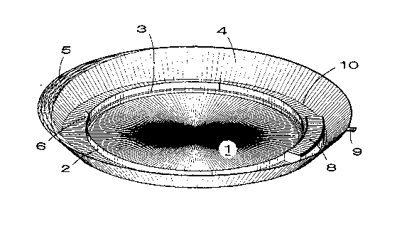
In drawings which illustrate the embodiment of the invention,
Figure 1 is a front-plan view of the embodiment of the invention;
Figure 2 a is top view of the embodiment of the invention; Figure
3 is a side cross sectional view of the embodiment of the
invention shown attached to a conventional paint can; and Figure
4 is side cross sectional view of an embodiment of the invention
shown in stacked position with respect to similarly configured
drip/spill guard devices.

2144902
The device illustrated comprises a base section 1 being circular
in shape which is larger in surface area than a conventionally
sized paint can.
Protruding from the upper abutment surface of the base section 1
is a retaining wall 2 which features a circumferential pressure
clip 3 designed to detachably secure the drip/spill guard device
to the bottom rim of the paint can, as shown in FIG. 3.
A containment flange 4 is attached circumferentially to the base
section 1 and extends upwardly and outwardly at a prescribed
angle to a prescribed height. Together the containment flange 4
and the base section 1 form a containment chamber 10 having the
function of receiving and retaining paint that has dripped or
spilled down the side of the paint can. The prescribed angle of
the circumferential flange 4 also renders the device stackable as
viewed in FIG.4. This stacking capability FIG. 4 economizes the
space required for the storage and shipping of the drip/spill
guard devices. Also attached to the edge of the containment
flange 4 is a tab 9 which allows the device 10 to be hung on
display hooks for marketing purposes.
A containment lip 5 is attached to the edge of the containment
flange 4 corresponding to the pouring side of the paint can. The
function of this containment lip 5 is to prevent already
contained paint from spilling out of the containment chamber 10
when the paint can is tilted to pour paint.
A number of vertical strips 6 are located in the containment
chamber 10 and are fastened to the retaining wall 2 for the
purpose of guiding the paint can into the circumferential
pressure clip 3.

- 214~902
The circumferential pressure clip 3 is designed to contour the
bottom rim of the paint can, thus forming a platform ring 7 to
ensure minimum surface contact with any surface supporting the
device (i.e. the floor).
A moulded pouring grip 8 is located opposite the containing lip 5
on the under side of the base section 1. Its function is to
provide a way of gripping the device so that soiled hands do not
have to touch the platforn ring 7 which makes contact with the
floor.
In operation the present invention is utilized by placing a
drip/spill guard device on the floor, or on any other solid
supporting surface. Next the paint can is centred the over the
drip/spill guard device and is lowered until it makes contact
with the vertical guiding strips 6. After pushing the can into
the circumferential pressure clip 3, the drip/spill guard device
becomes detachably secured to the paint can. When the user of
the drip/spill guard device wishes to remove the device from the
paint can, all that is required is a simple downward pressure on
the containment flange. At this point the drip/spill guard can
be set aside until the paint has dried, at which time the paint
can be peeled out of the containment chamber, or alternatively,
the user can wipe the containment chamber 10 with water or
solvent to remove the spilled paint.

Representative Drawing
A single figure which represents the drawing illustrating the invention.
Administrative Status

2024-08-01:As part of the Next Generation Patents (NGP) transition, the Canadian Patents Database (CPD) now contains a more detailed Event History, which replicates the Event Log of our new back-office solution.

Please note that "Inactive:" events refers to events no longer in use in our new back-office solution.

For a clearer understanding of the status of the application/patent presented on this page, the site Disclaimer , as well as the definitions for Patent , Event History , Maintenance Fee  and Payment History  should be consulted.

Event History

Description Date
Time Limit for Reversal Expired 1998-03-17
Application Not Reinstated by Deadline 1998-03-17
Deemed Abandoned - Failure to Respond to Maintenance Fee Notice 1997-03-17
Application Published (Open to Public Inspection) 1996-09-18

Abandonment History

Abandonment Date Reason Reinstatement Date
1997-03-17
Owners on Record

Note: Records showing the ownership history in alphabetical order.

Current Owners on Record
ANDREW M. STRINGER
Past Owners on Record
None
Past Owners that do not appear in the "Owners on Record" listing will appear in other documentation within the application.
Documents

To view selected files, please enter reCAPTCHA code :


To view images, click a link in the Document Description column. To download the documents, select one or more checkboxes in the first column and then click the "Download Selected in PDF format (Zip Archive)" or the "Download Selected as Single PDF" button.

List of published and non-published patent-specific documents on the CPD .

If you have any difficulty accessing content, you can call the Client Service Centre at 1-866-997-1936 or send them an e-mail at CIPO Client Service Centre.


Document
Description 
Date
(yyyy-mm-dd) 
Number of pages   Size of Image (KB) 
Representative drawing 1997-12-11 1 48
Drawings 1996-09-18 2 102
Description 1996-09-18 4 123
Abstract 1996-09-18 1 26
Cover Page 1996-10-09 1 13
Claims 1996-09-18 2 60
Notice: Maintenance Fee Reminder 1997-12-18 1 119