Language selection

Search

Patent 2145052 Summary

Third-party information liability

Some of the information on this Web page has been provided by external sources. The Government of Canada is not responsible for the accuracy, reliability or currency of the information supplied by external sources. Users wishing to rely upon this information should consult directly with the source of the information. Content provided by external sources is not subject to official languages, privacy and accessibility requirements.

Claims and Abstract availability

Any discrepancies in the text and image of the Claims and Abstract are due to differing posting times. Text of the Claims and Abstract are posted:

  • At the time the application is open to public inspection;
  • At the time of issue of the patent (grant).
(12) Patent Application: (11) CA 2145052
(54) English Title: PALETTE
(54) French Title: PALETTE AMELIOREE
Status: Deemed Abandoned and Beyond the Period of Reinstatement - Pending Response to Notice of Disregarded Communication
Bibliographic Data
(51) International Patent Classification (IPC):
  • B65D 19/40 (2006.01)
  • B65D 19/08 (2006.01)
  • B65D 77/04 (2006.01)
  • B65D 77/06 (2006.01)
(72) Inventors :
  • SCHUTZ, UDO (Germany)
(73) Owners :
  • SCHUTZ-WERKE GMBH & CO. KG
(71) Applicants :
  • SCHUTZ-WERKE GMBH & CO. KG (Germany)
(74) Agent: SMART & BIGGAR LP
(74) Associate agent:
(45) Issued:
(22) Filed Date: 1995-03-20
(41) Open to Public Inspection: 1995-09-22
Examination requested: 1995-04-13
Availability of licence: N/A
Dedicated to the Public: N/A
(25) Language of filing: English

Patent Cooperation Treaty (PCT): No

(30) Application Priority Data:
Application No. Country/Territory Date
G 94 04 764.2 (Germany) 1994-03-21

Abstracts

English Abstract


It involves a palette (1) made of steel or plastic,
with a subframe (2), corner feet (7) and center feet (15, 16)
a base pan (8) made of sheet metal, resting on feet (7, 15,
16), with a drainage bottom (9), which has a drainage channel
(10). Base pan (8) holds, with positive fit, an internal
container (11) made of plastic with an outer jacket (12) made
of sheet metal or lattice work and a drainage bottom (13), or
forms part of a sheet metal container. A stiffening sheet
(14), made like a girder, is fastened under the base pan (8),
crosswise to its drainage channel (10). Further to provide
greater transport security and simplification of construction,
two center feet (15, 16) are integrally molded on both ends
(14a, 14b) of the stiffening sheet (14) that is made like a
bridge.


Claims

Note: Claims are shown in the official language in which they were submitted.

THE EMBODIMENTS OF THE INVENTION IN WHICH AN EXCLUSIVE
PROPERTY OR PRIVILEGE IS CLAIMED ARE DEFINED AS FOLLOWS:
1. In a palette with a subframe and feet, a base pan
resting on the feet and made of sheet metal with a drainage
bottom that has a drainage channel, the base pan holding an
internal container, and a stiffening strip of bent cross-
section fastened under the base pan crosswise to said drainage
channel; the improvement comprising two supporting center feet
(15, 16) integrally formed on opposite ends (14a, 14b) of said
stiffening strip (14).
2. Palette according to claim 1, wherein a section
(14c) of said stiffening strip (14) merges via legs (17, 18)
oriented outward at an angle, with said center feet (15, 16).
3. Palette according to claim 1, wherein said
stiffening strip (14) and center feet (15, 16) are bent in a
plurality of directions in cross-section.
4. Palette according to claim 1, wherein said
stiffening strip (14) is a press-drawn part.
- 4 -

Description

Note: Descriptions are shown in the official language in which they were submitted.


2145052
The lnventlon relates to a palette of steel or
plastic wlth a subframe, corner and mlddle feet, a base pan of
sheet metal restlng on the feet and wlth a dralnage bottom
that has a dralnage channel, and the base pan holds, wlth
posltlve flt, an lnslde contalner made of plastlc wlth an
outer ~acket of sheet metal or lattlce work and a dralnage
bottom, or forms part of a sheet metal contalner, as well as
wlth a stlffenlng sheet, made llke a glrder, fastened under
the base pan, crosswlse to lts dralnage channel.
In a palette of thls type known from DE 42 06 945
Cl, the stlffenlng sheet fastened centrally between both cross
frames of the frame for the feet ls welded or screwed to two
center feet, whlch ln turn are welded to both lengthwlse
frames of the palette.
Besldes the relatlvely expenslve manufacturlng
caused by lts structure, thls palette has the further drawback
that, because of bendlng stress loads caused by wave
osclllatlons belng emanated durlng the transport of llqulds ln
the contalner and by motlon osclllatlons transmltted to the
palette by the transport vehlcle, the base pan, ln the area of
the connectlon polnts between both center feet and the
stlffenlng sheet, because of a relatlvely qulck fatlgue of the
sheet metal materlal, gets tears, so that the transport safety
of the palette ls no longer guaranteed.
The ob~ect of the invention is to further develop
the generic palette with respect to greater transport safety
and a simplificatlon of the construction, wlth the goal of
economlcal manufacturing.
The one-piece, bridge-like design of the stiffening
-- 1 --
26636-54

21~50~2
sheet for the base pan of the palette, together wlth two
center feet, makes lt posslble to have a favorable
lntroduction of the occurrlng bendlng forces from the base of
the base pan, through the brldge-llke stlffenlng sheet, lnto
the center feet, 80 that the formatlon of tears ln the base
pan ls avolded and thus the transport safety of the palette ls
guaranteed. ~y produclng the stlffenlng sheet together wlth
both center feet as a press-drawn part, the strength of thls
part ls agaln lncreased because of the cold formlng, and the
manufacturlng of the palette becomes slmpler and thus less
expenslve.
The lnventlon ls descrlbed ln more detall below
based on an embodlment represented ln the drawlng. There are
shown ln
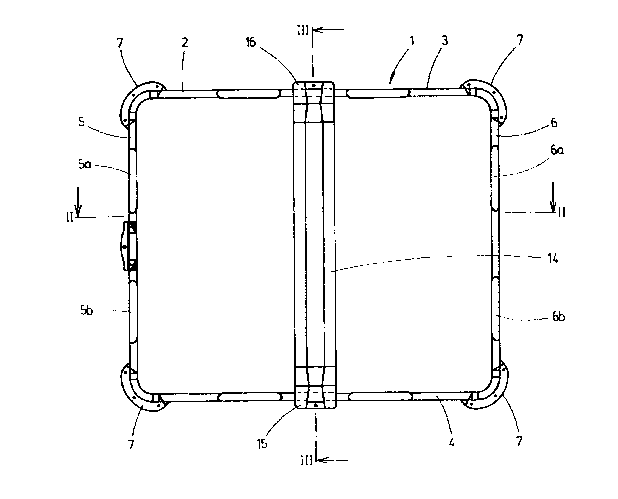
Flgure 1, a top vlew of a palette wlthout base pan,
Flgure 2, a lengthwlse sectlon of the palette along
llne II-II and
Flgure 3, a cross sectlon of the palette along llne
III-III of Flgure 1 wlth base pan ln an enlarged
representatlon and
Flgures 4 to 7, cross sectlons through the
stlffenlng sheet and a center foot along llne IV-IV, V-V, VI-
VI, and VII-VII of Flgure 3 ln an enlarged representatlon.
Palette 1 has a rectangular subframe 2 made of steel
tube wlth two lengthwlse frames 3, 4 and two cross frames 5,
6. Four corner feet 7 are welded on subframe 2. Two support
yokes 5a, 5b and 6a, 6b are extruded ln each case on both
cross frames 5, 6.
A base pan 8 made of sheet metal ls tlghtly screwed
-- 2
26636-54

2195052
onto four corner feet 7 and four support yokes 5a, 5b and 6a,
6b of cross frames 5, 6 of subframe 2.
Bottom 9 of base pan 8 descends sllghtly from both
lateral pan edges 8a, 8b toward the center of the bottom and,
further, lt has a sllght slope from rear pan edge 8c toward
front pan edge 8d. In thls way, bottom 9 of pan 8 forms a
flat dralnage channel 10 runnlng wlth a sllght slope from rear
pan edge 8c toward front pan edge 8d.
Base pan 8 of palette 1 holds, wlth posltlve flt, an
lnternal contalner 11 made of plastlc wlth an outer ~acket 12
made of sheet metal and a dralnage bottom 13.
A stlffenlng sheet 14, made llke a glrder, ls
tlghtly screwed ln under bottom 9 of base pan 8, centrally
between cross frames 5, 6 and runnlng crosswlse to dralnage
channel 10 of the pan, a stlffenlng sheet on both of whose
ends 14a, 14b two center feet 15, 16 are lntegrally molded,
whlch are welded wlth lengthwlse frames 3, 4 of subframe 2.
Sectlon 14c of stlffenlng sheet 14 fastened under
base pan 8 merges, vla legs 17, 18 that are orlented outward
at an angle, wlth center feet 15, 16.
Stlffenlng sheet 14 wlth center feet 15, 16 ls
deslgned as a proflle part and produced as a press-draw part.
26636-54

Representative Drawing
A single figure which represents the drawing illustrating the invention.
Administrative Status

2024-08-01:As part of the Next Generation Patents (NGP) transition, the Canadian Patents Database (CPD) now contains a more detailed Event History, which replicates the Event Log of our new back-office solution.

Please note that "Inactive:" events refers to events no longer in use in our new back-office solution.

For a clearer understanding of the status of the application/patent presented on this page, the site Disclaimer , as well as the definitions for Patent , Event History , Maintenance Fee  and Payment History  should be consulted.

Event History

Description Date
Inactive: IPC from MCD 2006-03-11
Application Not Reinstated by Deadline 1998-11-06
Inactive: Dead - No reply to s.30(2) Rules requisition 1998-11-06
Deemed Abandoned - Failure to Respond to Maintenance Fee Notice 1998-03-20
Inactive: Status info is complete as of Log entry date 1998-02-24
Inactive: Abandoned - No reply to s.30(2) Rules requisition 1997-11-06
Inactive: S.30(2) Rules - Examiner requisition 1997-05-06
Application Published (Open to Public Inspection) 1995-09-22
All Requirements for Examination Determined Compliant 1995-04-13
Request for Examination Requirements Determined Compliant 1995-04-13

Abandonment History

Abandonment Date Reason Reinstatement Date
1998-03-20
Owners on Record

Note: Records showing the ownership history in alphabetical order.

Current Owners on Record
SCHUTZ-WERKE GMBH & CO. KG
Past Owners on Record
UDO SCHUTZ
Past Owners that do not appear in the "Owners on Record" listing will appear in other documentation within the application.
Documents

To view selected files, please enter reCAPTCHA code :


To view images, click a link in the Document Description column. To download the documents, select one or more checkboxes in the first column and then click the "Download Selected in PDF format (Zip Archive)" or the "Download Selected as Single PDF" button.

List of published and non-published patent-specific documents on the CPD .

If you have any difficulty accessing content, you can call the Client Service Centre at 1-866-997-1936 or send them an e-mail at CIPO Client Service Centre.


Document
Description 
Date
(yyyy-mm-dd) 
Number of pages   Size of Image (KB) 
Description 1995-09-22 3 111
Cover Page 1995-11-08 1 15
Abstract 1995-09-22 1 21
Drawings 1995-09-22 4 58
Claims 1995-09-22 1 28
Representative drawing 1998-08-04 1 11
Courtesy - Abandonment Letter (R30(2)) 1998-02-25 1 173
Courtesy - Abandonment Letter (Maintenance Fee) 1998-04-20 1 186
Fees 1996-10-22 1 52
Prosecution correspondence 1995-04-13 1 40
PCT Correspondence 1995-05-23 1 25
Courtesy - Office Letter 1995-05-04 2 39
Courtesy - Office Letter 1995-05-04 1 10
Prosecution correspondence 1995-06-15 1 21
Prosecution correspondence 1995-04-20 1 33
Examiner Requisition 1995-09-20 1 55
Examiner Requisition 1997-05-06 2 76