Note: Descriptions are shown in the official language in which they were submitted.
,~ 21 ~ g,
This invention relatel3 to bird f eeders and particularly to a
bird feeder having provisions to prevent the feed therein from
being consumed by other animals.
A perpetual n~ n~e to })ird lover3 is that the feed provided
5 within a bird feeder is regularly pilfered by other animals gaining
access to the feed. Some hanging bird feeders may deter other
animals from consuming the feed due to the difficulty in gaining
access to the feeding openings of the feeder, yet animal3 ~uch as
a squirrel may still intrude into such feeder to filch at the feed
10 intended for birds only.
The principal object of l:he present invention is to provide a
bird feeder which effectively prevents other animals from gaining
access to the feed contained therein.
Another object of the present invention i3 to provide a bird
15 feeder having a relatively simple construction and is easy to use.
Another object of the present invention is to provide a bird
feeder in which the feed is effectively protected from rain and
wind .
Another object of the present invention is to provide a bird
20 feeder in which the feed il3 automatically replenished from a
~3torage area a 3 it is consumed by the birds .
The feeder according to the present invention comprises an
~ 21~
open top inner casing having cl top portion therein for storing the
bird feed and a lower chamber in which the feed can be C~ ' by
the birds. The inner casing is covered by an open bottom outer
casing. The outer casing is mounted to a hanging rod through a
5 tension spring assembly such t:hat the outer casing is displaceable
in an up and down manner relative to the hanging rod. The inner
casing is disposed within the outer casing and is f ixedly mounted
to the hanging rod such that when the outer casing is displaced
relative to the hanging rod it would also inherently displace
10 relative to the inner casing. Feeding openings are provided at all
sides of the outer casing and the sides of the inner casing in the
lower chamber portion. These openings are normally aligned such
that they are opened to allow the birds to gain access of the feed
within the lower chamber of the feeder. When an animal having a
15 body weight heavier than a bird lands on the outer ca~ing, it would
cause the outer casing to displace relative the inner casing to
close the feeding openings, thus preventing the feed from being
pilf ered by the animal .
Other object and advantages of the present invention will
20 become apparent from the foLlowing detailed description of the
preferred embodiments thereof in connection with the ao~ ,-nying
drawings in which
21~51~9
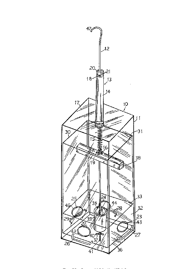
Figure 1 is a perspective view ~f the bird feeder according to
the present invention.
Figure 2 is a partial cross sectional front view thereof
showing a bird feeding on the feed contained within the feeder.
Figure 3 is a f ront elevation view thereof showing the
displacement of the outer casing when a squirrel is sitting on the
top of the outer casing.
Figure 4 is a bottom elevation view thereof.
With reference to the drawings wherein like reference numerals
designate corresponding parts in the several views, the bird feeder
10 according to the present invention comprises an opened bottom
outer casing 11. For convenience cf illustrationr the feeder is
shown to have a square cross sectional shape. It will be
appreciated by those skilled in the art that the feeder may have a
rectangular, or circular, or other selected cross sectional shapes.
The outer casing 11 is preferably made of a transparent plastic
material . The reason f or using such material will become apparent
in the following description. The outer casing 11 is mounted to an
elongated hanging rod 12 through a compression spring assembly 13
which consists of a closed tol~ tubing 14, a compression spring 15,
and a securing coupling sleeve 16. The bottom portion of the tubing
14 is secured to the top 17 of the outer casing 11. The hanging rod
~ 21~S1~9
12 extends slidably through a centre opening 18 located at the top
of the clo3ed top tubing 14. The top portion of the compression
spring 15 is slidably located within the closed top tubing 14, and
its lower portion extends outside of the tubing 14. The bottom
portion of the compression ~pring 15 engages with the coupling
sleeve 16 which is secured to the hanging rod 12 by a set screw 19.
The coupling sleeve 16 iB located at the position on the hanging
rod 12 at which the bottom end of the relaxed compression spring 15
is located. The upper end of the closed top tubing 14 is retained
in place by an abutment ring 20 which is secured to the hanging rod
12 by a set screw. The abutment ring 20 is located at the position
on the hanging rod 12 at whicll the top of the closed top tubing 14
is located when the compression spring 15 is in the relaxed state.
The outer casing 11 is movab3 e relative to the hanging rod 12 by
exerting a force on the top t~lereon 80 that it slides downwards by
~ ~ssing the c~ ~ ~ssion sE~ring 15 between the closed top of the
tubing 14 and the coupling sleeve 16.
Access openings 22, 23, 24 and 25 are provided respectively at
the four sides of the lower portion of the outer casing 11 as best
shown in Figure 1. Four U-shaped brackets 26, 27, 28 and 29 are
mounted respectively in the hc~rizontal manner just below the access
openings 22, 23, 24, and 25 respectively.
~ 21~14~
An opened top inner ca3irlg 30 is slidably disposed within the
outer casing 11. Similar to the outer casing 11, the inner casing
30 i3 also made of transparent plastic material. The inner casing
30 is separated into a relatively larger top bin portion 31 and a
5 smaller lower chamber 32 by a horizontal partition panel . The top
bin portion 31 c~ i r~ates ~ith the lower chamber 32 through an
opening 34 in the partition panel 33. A chuting sleeve 35 is
secured to the partition pa]lel 33 and extends downwards below
therefrom. The bottom end of the chuting sleeve 35 is spaced from
the bottom panel 36 of the inner casing 30. The hanging rod 12
extends through a centre opening 37 provided at the bottom panel 36
of the inner casing 30. A hori.zontal restraining bar 38 is located
in a transverse manner adjacellt the opened top of the inner casing
30. A through opening 39 is formed at the centre of the restraining
bar 38. The inner casing 30 is mounted to the hanging rod 12 by
inserting the hanging rod 12 slidably through the through opening
39 of the re~training bar 38 and the centre opening 37 of the
bottom panel 36 in the inner casing, and it is held in place by a
wing nut 4 0 secured to the threaded bottom portion 41 of the
20 hanging rod 12. Thus, the inner casing 30 is retained in place on
the hanging rod 30 between the wing nut 40 and the restraining bar
38.
* 2~4~I~9
A~sociated access openin~s 42, 43, 44 and 45 are formed at the
side!a of the lower chamber 32 of the inner casing 30. ~he
Associated access openings 42, 43, 44 and 45 are aligned ~ith the
access openings 22, 23, 24 alld 25 in the outer casing 11 in the
5 normal position when the compre~sion spring 15 is in the relaxed
state .
In use, the inner casing 30 is first removed from the assembly
and the feed 46 i3 poured into the top bin portion 31. The inner
casing 30 with the feed 46 contained therein is then slidably
10 inserted through the opened bottom of the outer casing 11 by
inserting the hanging rod 12 through the retraining bar 38 and the
bottom panel 36, and it is secured in place by the wing nut 40. The
feeder 10 may be hung onto a horizontal bar or a tree branch by the
hook shape upper end 47 provided in the hanging rod 12. A
15 proportioned amount of the feed 46 will fall from the top bin
portion 31 of the inner casin~ 31 into the lower chamber 32. Birds
may consume the feed in the lower chamber 32 through the access
openings by standing on the U-shaped brackets 26, 27, 28 or 29 as
best shown in Figure 2. The feed in the top bin portion 31 will
20 automatically fall by gravity into the lower chamber 36 through the
chuting sleeve 35 to repleni3h it as the feed therein is C~n~
by the birds.
~ 214S1~9
When an animal such as a squirrel lands on the f eed as best
3hown in Figure 3, the body waight of the ~3quirrel will cause the
outer casing 11 to displace downwardY by compressing the
compres~3ion spring 15. The displacement will cause the access
5 openings and the associated access openings to misalign with each
other as best shown in Figur~a 3, thus it ef f ectively closes the
access openings to the lower ~hamber 36 of the inner casing 30 to
prevent the intruding animal i-rom having access to the feed within
the inner casing.
The feed 46 within the inner casing 30 is protected from wind
and rain by the outer casing 11.
The transparent material used for making the inner casing and
outer casing allows the visua] determination of the amount of feed
I~ i ni n J in the top bin portion 32 of the inner casing.
15 Fur~h~ , the squirrel is ~Inable to climb down the sides of the
feeder due to the plastic material used for making the outer
casing .
While certain preferred ~ ' orl;l 18 of the present invention
have been disclosed in detail, it is to be understood that various
20 modifications may be adopted without departing from the spirit of
the invention or scope of the following claims.