Note: Descriptions are shown in the official language in which they were submitted.
WO 94/06350 2 1 ~ 5 1 8 ~ PCI/US93/08782
CARDIAC VULNERABILITY TRACKING METHOD AND APPARATUS
5 STATEMENT AS TO RIGHTS TO INVENTIONS MADE UNDER
FEDERALLY SPONSORED RESEARCH AND DEVELOPMENT
Part of the work performed during development of this invention
utilized U.S. Government funds. The U.S. Government has certain rights in
this invention.
10 BACKGROUND OF THE INVENTION
1. ~ELATED APPLICATION
This application is a confinll~tion-in-part of application serial number
07/768,054, filed September 30, 1991, to issue as U.S. Pat. No. 5,148,812
on September 22, 1992; which is a continuation-in-part of application serial
number 07/659,711, filed February 20, 1991, now abandoned.
2. F1:FLD OF T IE INVENTION
The invention relates to cardiology. More specihcally, the invention
relates to non-invasive identification and management of individuals at risk forsudden cardiac death. Cardiac vulnerability to ventricular fibrillation, the
20 mode of sudden death, is dynamically tracked by analysis of an
electrocardiogram .
3. RE~ATED ART
Sudden cardiac death (SCD), which claims over 350,000 lives annually
in the United States, results from abrupt disruption of heart rhythm primarily
25 due to ventricular fibrillation. Fibrillation occurs when transient neural
triggers impinge upon an electrically unstable heart causing normally
organized electrical activity to become disorganized and chaotic. Complete
cardiac dysfunction results.
WO 94/063S0 PCr/US93/08782
S~ ~: ~
-2 -
The first step in preventing sudden cardiac death is identifying those
individuals whose hearts are electrically unstable. This is a major objective
in cardiology. If vulnerable individuals can be reliably identified non- '.
invasively, then prevention will be aided, mass screening will become
possible, and pharmacologic management of vulnerable individuals can be
tailored to prevent ventricular fibrillation.
Programmed cardiac electrical stimulation has been used in patients to
provide quantitative information on susceptibility and on the effectiveness of
their pharmacologic therapy. Unfortunately, this method requires cardiac
catheterization and introduces the hazard of inadvertent induction of
ventricular fibrillation. Therefore, it is used only in severely ill patients and
is performed only in hospitals. It is unsuitable for mass screening.
A technique which has shown great promise is that of analyzing
alternans in the T-wave of an electrocardiogram (ECG). As used throughout
this disclosure, the term "T-wave" is defined to mean the portion of an ECG
which includes both the T-wave and the ST segment. Alternans in the T-wave
results from different rates of re-polarization of the muscle cells of the
ventricles. The extent to which these cells recover (or re-polarize) non-
uniformly is the basis for electrical instability of the heart.
The consistent occurrence of alternans in the T-wave prior to
fibrillation is well established. Thus, detection of alternans promises to be a
useful tool in predicting vulnerability to fibrillation, if an accurate method of
quantifying the alternans can be developed. The following are examples of
conventional attempts to quantify alternation in an ECG signal: Dan R. Adam
et al., "Fluctuations in T-Wave Morphology and Susceptibility to Ventricular
Fibrillation," Journal of Electrocardiology, Vol. 17 (3), 209-218 (1984);
Joseph M. Smith et al. "Electrical Alternans and Cardiac Electrical
Instability," Circulation, Vol. 77, No. 1, 110-121 (1988); U.S. Pat. No.
4,732,157 to Kaplan et al.; and U.S. Pat. No. 4,802,491 to Cohen et al. c
Smith et al. and Cohen et al. disclose methods for assessing myocardial
electrical instability by power spectrum analysis of the T-wave. These
methods derive an alternating ECG morphology index from a series of
WO 94/06350 2 1~ ~ 1 8 ~ PCI/US93/08782
-3-
heartbeats. Sample point matrices are constructed and the alternating energy
at each of the sample points is computed using the analytical method of multi-
dimensional power spectral estimation which is calculated by constructing the
discrete Fourier transform of the Hanning-windowed sample auto-correlation
5 function. The alternating energy over the entire set of sample points is
sllmmecl to generate the total alternating energy and then normalized with
respect to the average waveform to produce an "alternating ECG morphology
index (AEMI)."
While a powerful tool, Fourier power spectrum analysis averages time
10 functions over the entire time series so that rapid arrhythmogenic changes,
such as those due to neural discharge and reperfusion, are not detected because
data from these events are intrinsically non-stationary.
Kaplan et al. disclose a method for quantifying cycle-to-cycle variation
of a physiologic waveform such as the ECG for the purpose of "~sessin~
15 myocardial electrical stability. A physiologic waveform is digitized and
sampled and a scatter plot of the samples is created. Non-linear
transformation of the sample points determines a single parameter which
attempts to quantify the degree of alternation in the sampled waveform and
which is associated with the susceptibility of the physiologic waveform to enter20 into an aperiodic or chaotic state. Kaplan et al. suggest that "measurement of
[this parameter] may provide an index of ECG waveform variability which
may provide an improved correlation with susceptibility to ventricular
fibrillation than previously available indices. " See col.3, lines 15-19. Whether
ventricular fibrillation is a chaotic state, however, is still very much in debate.
25 See D.T. Kaplan and R. J. Cohen, "Searching for Chaos in Fibrillation," Ann.
N.Y. Acad. Sci., Vol. 591, pp. 367-374, 1990.
Adam et al. disclose a non-invasive method which involves spectral
analysis of the alternation from beat-to-beat morphology of the ECG complex.
The alternation of T-wave ener~y from beat-to-beat was measured to generate
30 a T-wave alternation index (TWAI). This technique is unable to detect
alternation in waveform morphology which results in alternating wave shapes
of equal energy. In addition, the amount of alternation detected per this
WO 94/06350 PCrtUS93/08782
2~,~5~8
method is dependent on the static portion of the wave shape. That is, the
same amount of alternation superimposed on a different amplitude signal will
result in different values for the T-wave alternation index such that this
technique could completely obscure the presence of alternation in the original
waveform morphologies.
In the absence of an effective method for dynamically quantifying the
magnitude of alternation, identification of alternans as a precursor of life-
threatening arrhythmias and provision of a test for cardiac vulnerability have
been unattainable. In addition, the conventional attempts to quantify alternans
have employed inferior methods of alternans (i.e., ECG) sensing. The ECG
signals used for the Cohen et al. analysis were sensed via epicardial (i.e.,
heart surface) electrodes or via lateral limb, rostral-caudal, and dorsal-ventral
leads. Smith et al. sensed via leads I, aVF, and Vl 2. Adam et al. utilized
ECG lead I "because in this lead the ratio of the amplitude of the pacing
stimulus artifact to the amplitude of the QRS complex was usually smallest."
See Adam et al. at 210. Lead I, however, provides only limited information
regarding the electrophysiologic processes occurring in the heart.
There have been occasional reports in the human literature noting the
presence of T-wave alternans in the precordial leads. However, there has
been no suggestion of a superior lead configuration from the body surface
which permits measurement of alternans as a quantitative predictor of
susceptibility to ventricular fibrillation and sudden death. For example,
alternans have been observed in precordial leads V4 and Vs during a PCTA
(Percutaneous Transluminal Coronary Angioplasty) procedure on a fifty year-
old man. M. Joyal et al., "ST-Segment Alternans During Percutaneous
Transluminal Coronary Angioplasty," Am. J. Cardiol., vol. 54, pp. 915-916
(1984). Similarly, alternans were noted in precordial leads V4 through V6 on
a forty-four year-old man during and following a treadmill exercise. N. Belic,
et al., "ECG Manifestations of Myocardial Ischemia," Arch. Intern. Med.,
vol. 140, pages 1162-1165 (1980).
Another method which has been explored to assess autonomic nervous
system activity, the neural basis for vulnerability to sudden cardiac death is
WO 94/06350 ' 2 I ~ ~1 8 l~ PCr/US93/08782
--5--
analysis of heart rate variability (HRV). Heart rate variability, however, is
not an absolute predictor of SCD because there are major, non-neural factors
which contribute to sudden death. These include: coronary artery disease,
heart failure, myopathies, drugs, caffeine, smoke, environmental factors, and
5 others. Accordingly, techniques which rely on heart rate variability to predict
cardiac electrical stability are not reliable.
Further, conventional techniques for analyzing heart rate variability
have relied on power spectrum analysis. See, for example, Glenn A. Myers
et al., "Power Spectral Analysis of Heart Rate Variability in Sudden Cardiac
10 Death: Comparison to Other Methods," IEEE Transactions on Biomedical
Engineering, Vol. BME-33, No. 12, December 1986, pp. 1149-1156. As
discussed above, however, power spectrum (Fourier) analysis averages time
functions over an entire time series so that rapid arrhythmogenic changes are
not detected.
Complex demodulation as a method for analyzing heart rate variability
is discussed in Shin et al., "Assessment of Autonomic Regulation of Heart
Rate Variability by the Method of Complex Demodulation," IEEE
Transactions on Biomedical Engineering, Vol. 36, No. 2, February 1989,
which is incorporated herein by reference. Shin et al. teach a method of
20 evaluating the influence of autonomic nervous system activity during
behavioral stress. A technique of complex demodulation is used to analyze the
pattern of beat-to-beat intervals to determine the relative activity of the
sympathetic and parasympathetic nervous systems. While Shin et al. exploited
the dynamic analytical characteristics of complex demodulation, they did not
25 relate their results to cardiac vulnerability.
Similarly, T. Kiauta et al. "Complex demodulation of heart rate
changes during orthostatic testing," Proceedings Computers in Cardiology,
(Cat. No. 90CH3011-4), IEEE Computer Society Press, 1991, pp. 159-162,
discusses the use of complex demodulation to assess heart rate variability
30 induced by the standing-up motion in young healthy subjects. Using the
technique of complex demodulation, Kiauta et al. conclude that the complex
demodulate of the high frequency band probably reflects parasympathetic
Wo 94/06350 PCr/US93/08782
Q
--6-
activity, but the complex demodulate of the low frequency band does not seem
to indicate sympathetic activity. Similar to Shin et al., Kiauta et al. do not
relate their results to cardiac vulnerability.
In sllmm~ry, analysis of the morphology of an ECG (i.e., T-wave
5 alternans) has been recognized as a means for assessing cardiac vulnerability.Similarly, analysis of heart rate variability has been proposed as a means for
~sessing autonomic nervous system activity, the neural basis for cardiac
vulnerability. When researching vulnerability to sudden cardiac death,
researchers have conventionally relied on power spectrum (Fourier) analysis.
10 However, power spectrum analysis is not capable of tracking many of the
rapid arrhythmogenic changes which characterize T-wave alternans and heart
rate variability. As a result, a non-invasive diagnostic method of predicting
vulnerability to sudden cardiac death by analysis of an ECG has not achieved
clinical use.
What is needed is a non-invasive, dynamic method for completely
~sessing vulnerability to ventricular fibrillation under diverse pathologic
conditions relevant to the problem of sudden cardiac death. Among the most
significant problems are enhanced discharge by the sympathetic nervous
system, behavioral stress, acute myocardial ischemia, reperfusion, effects of
20 pharmacologic agents on the autonomic nervous system, and intrinsic cardiac
effects of pharmacologic agents. To accommodate these conditions, the
method must not assume stationarity of data and must be sensitive to slowly
varying amplitude and phase over time. The diagnostic system must be
sensitive to the fact that the area of injury to the heart can vary significantly,
25 that extrinsic as well as intrinsic influences affect the electrical stability of the
heart, and that the electrophysiologic end point to be detected must be
fundamentally linked to cardiac vulnerability.
WO 94/06350 2 1 ~ 5 1 ~ ~ PCr/US93/08782
.
-7--
SUMMARY OF THE INVENTION
The present invention is a method and apparatus for non-invasive,
dynamic tracking and diagnosing of cardiac vulnerability to ventricular
fibrillation. It is non-invasive as it detects vulnerability from leads placed on
5 the surface of the chest. Tracking and diagnosis of cardiac electrical stability
are achieved through simultaneous assessment of both T-wave alternans and
heart rate variability. The method permits tracking of transient but deadly
pathophysiologic events, such as enhanced discharge by the sympathetic
nervous system, behavioral stress, acute myocardial ischemia and reperfusion.
T-wave alternans and heart rate variability are simultaneously
evaluated. T-wave alternation is an absolute predictor of cardiac electrical
stability. Heart rate variability is a measure of autonomic influence, a major
factor in triggering cardiac arrythmias. By simultaneously analyzing both
phenomena, the extent and cause of cardiac vulnerability can be ~s~ssed.
15 This has important ramifications for tailoring and assessing the efficacy of
drug therapy.
The method includes the following steps. A heart is monitored to sense
an ECG signal. The sensed ECG signal is then amplified and low-pass filtered
before it is digitally sampled and stored. F~tim~tion of alternans amplitude
20 and analysis of heart rate variability are then separately performed.
F~tim~tion of the amplitude of alternans is performed as follows. The
location of the T-wave in each R-R interval (heart beat) of the ECG is
estimated, and each T-wave is partitioned into a plurality of time divisions.
The sampled ECG signal in each of the time divisions is summed together and
25 a time series is formed for each of the time divisions such that each time series
includes corresponding time divisions from successive T-waves. The time
series are detrended before further processing in order to remove the effects
of drift and DC bias.
Dynamic estim~tion is performed on each time series to estimate the
30 amplitude of alternation for each time division. The preferred method of
dynamic estimation is Complex Demodulation. Other methods include
F.stim~tion by Subtraction, Least Squares F.srim~tion, Auto Regressive
WO 94/06350 PCr/US93/08782
8~ ~
-8-
F.~tim~tion, and Auto Regressive Moving Average F.~tim~tion. The amplitude
of alternation is used as an indication of cardiac susceptibility to ventricularfibrillation (i.e., cardiac electrical instability).
Analysis of heart rate variability is performed as follows. The apex of
each R-wave is determined, and the time between successive R-waves is
computed to determine a magnitude (time) of each R-R interval. The
magnitude of each R-R interval is then compared to a predetermined criterion
to eliminate premature beats. Next, a time series of the magnitudes of the R-
R intervals is formed. Dynamic estimation is performed on the time series to
estim~te the magnitude of a high frequency component of heart rate variability
and to estimate the magnitude of a low frequency component of heart rate
variability.
The magnitude of the high frequency component of heart rate
variability is indicative of parasympathetic activity. The magnitude of the low
frequency component of heart rate variability is indicative of combined
~.y~ allletic activity and parasympathetic activity. A ratio of the low
frequency component and the high frequency component of heart rate
variability is formed. The ratio is indicative of sympathetic activity or vagal
withdrawal.
In one embodiment of the invention~ the ECG is sensed non-invasively
via the precordial or chest leads. Leads Vs and/or V6 detect the optimal
alternans signal when the left side (the most common site of injury for the
propagation of life-threatening arrhythmias) of the heart is ischemic or injured.
Leads Vl and/or V2 are optimal for detecting obstruction of the right-sided
coronary circulation. Additional precordial leads, such as V9, may be useful
for sensing alternans resulting from remote posterior wall injury. A physician
may use the complete precordial lead system to obtain precise information
non-invasively regarding the locus of ischemia or injury.
In alternate embodiments, the ECG is sensed via a catheter inserted
into the apex of either the left or right ventricles of the heart.
WO 94/06350 . PCr/US93/08782
~ 2~4~18Q
g
BRIEF DESCRIPTION OF THE DRAWINGS
FIG. lA is a typical ECG plot.
FIG. lB shows a number of heart rate plots with corresponding spectral
plots.
FIG. 2A is high-level block diagram illustrating the diagnostic
principles of the present invention.
FIG. 2B is a block diagram illustrating the diagnostic principles of the
present invention in a first example.
FIG. 2C is high-level block diagram illustrating the diagnostic
principles of the present invention in a second example.
FIG. 3 is a flow chart illustrating the method of the present invention.
FIG. 4 is a flow chart ~let~iling the process of dynamically estim~ting
the amplitude of T-wave alternans (as performed in step 314 of FIG. 3).
FIG. 5 is a flow chart rlet~iling the process of dynamically analyzing
heart rate variability to determine the activity of the autonomic nervous system(as performed in step 314 of FIG. 3).
FIG. 6A is a high-level block diagram of the apparatus of the
invention.
FIG. 6B is a detailed block diagram of ECG detector and pre-processor
602.
FIG. 6C is a detailed block diagram of ECG processing system 604
compnslng a mlcroco~ uLer.
FIG. 7 is a detailed block diagram of the preferred embodiment of the
heart monitoring unit (HMU) 600.
FIG. 8(a) is an ECG recorded within the left ventricle of a dog before
coronary artery occlusion as set forth in the animal study below.
FIG. 8(b) shows superimposition of six sllccessive beats from FIG. 8(a)
presented on an expanded time scale.
FIG. 9(a) is an ECG recorded within the left ventricle of a dog after
four minutes of coronary artery occlusion as set forth in the animal study
below.
WO 94/06i~ ~; r~ 8 ~ PCI /US93/08782
-10-
FIG. 9(b) shows superimposition of six successive beats from FIG. 9(a)
presented on an expanded time scale.
FIG. 10(a) is an ECG recorded within the left ventricle of a dog after
release of the coronary artery occlusion (during reperfusion) as set forth in the
5 animal study below.
FIG. 10(b) shows superimposition of six successive beats from FIG.
10(a) presented on an expanded time scale.
FIG. 11(a) is a surface plot of the T-wave of the ECG for eight dogs
with intact cardiac innervation showing the effects of coronary artery occlusion10 and reperfusion.
FIG. 11(b) is a surface plot of the T-wave of the ECG for six dogs
after bilateral stellectomy showing the effects of coronary artery occlusion andreperfusion.
FIG. 11(c) is a surface plot of the T-wave of the ECG for eleven dogs
15 during thirty seconds of stimulation of the ansa subclavia of the decentralized
left stellate ganglion showing the effects of coronary artery occlusion and
reperfusion.
FIG. 12 shows the correlation between the occurrence of spontaneous
ventricular fibrillation and T-wave alternans in ten dogs.
FIG. 13 is a graph showing the responses of the sympathetic and
parasympathetic nervous systems to LAD coronary artery occlusion and
reperfusion as indicated by heart rate variability.
FIGS. 14(a)-(c) illustrate the positioning of the precordial ECG leads
on the body.
FIG. 15 is a cross-section of the human body illustrating the positioning
of precordial ECG leads Vl-V6 relative to the heart.
FIG. 16(a) is an ECG recorded from lead II during coronary artery
occlusion in a dog.
FIG. 16(b) shows superimposition of six successive beats from FIG.
30 16(a) presented on an expanded time scale.
FIG. 17(a) is an ECG from precordial lead V5 recorded simultaneously
with the ECG of FIG. 16(a).
WO 94/06350 ~ 8 ~ Pcr/US93/08782
.
-1 1-
FIG. 17(b) shows superimposition of six successive beats from FIG.
17(a) presented on an expanded time scale.
FIG. 18(a) is an ECG from a left ventricular intracavitary electrode
recorded simultaneously with the ECG of FIG. 16(a).
FIG. 18(b) shows superimposition of six successive beats from FIG.
18(a) presented on an expanded time scale.
FIG. 19 is a graph showing the relative magnitudes of alternans signals
sensed from lead II and from precordial lead V~ with reference to a left
ventricular intracavitary electrode.
FIG. 20 is a surface plot display obtained by the method of complex
demodulation (as set forth above) of the T-wave of the V4 precordial lead
during spontaneous heart rhythm in a representative patient during angioplasty.
FIG. 21 shows the level of T-wave alternans as a function of recording
site in seven patients at three minutes of angioplasty-induced occlusion and
15 upon balloon deflation.
DETAILED DESCRIPTION OF THE PREFERRED EMBODIMENT
INTRODUCTION
Figure lA shows a representative human surface ECG 100. A
deflection 102 is known as the "P-wave" and is due to excitation of the atria.
20 Deflections 104, 106 and 108 are known as the "Q-wave," "R-wave," and "S-
wave," respectively, and result from excitation (de-polarization) of the
ventricles. Deflection 110 is known as the "T-wave" and is due to recovery
(re-polarization) of the ventricles. One cycle (i.e., cardiac cycle or heart beat)
of the ECG from the apex of a first R-wave to the apex of the next R-wave
25 is known as the R-R or interbeat interval. Heart rate variability (HRV) refers
to changes in the heart rate (HR) or length (time) of the interbeat interval from
one beat to the next.
A portion 112 between S-wave 108 and T-wave 110 of ECG 100 is
known as the "ST segment". ST segment 112 includes the portion of the ECG
30 from the end of S-wave 108 to the beginning of the T-wave 110. Because this
invention is concerned with alternans in the ST segment as well as in the T-
WO 94/06350 PCr/US93/08782
12-
wave, the term "T-wave" in this disclosure, as noted above, includes both the
T-wave and the ST segment portions of the ECG.
The inventors have found that most alternans occurs in the first half of
the T-wave, the period of greatest vulnerability to ventricular fibrillation. See,
Nearing BD, Huang AH and Verrier RL, "Dynamic Tracking of Cardiac
Vulnerability by Complex Demodulation of the T Wave," Science 252:437-
440, 1991.
A more detailed discussion of ECG sensing and analysis is provided in
Dale Dubin, Rapid Interpretation of EKG's, 4~ Edition, Cover Publishing
Company, 1990, which is expressly incorporated herein by reference.
Conventionally, autonomic nervous system activity, as indicated by
heart rate variability, has been researched as an independent inrlic~tor of
cardiac vulnerability (electrical stability). Autonomic nervous system activity,however, is not an absolute predictor of cardiac vulnerability.
Further, conventional research has evaluated heart rate variability and
ECG morphology (as indicated by T-wave alternans) as independent variables
indicative of cardiac vulnerability. This also is an invalid assumption. HRV
and ECG morphology are linked, however, not invariably. Alternans can
change independently of HRV.
Heart rate variability and ECG morphology measure different aspects
of cardiovascular control. Both must be ~sessed in order to fully diagnose
cardiac vulnerability. The inventors have discovered that simultaneous
analysis of both heart rate variability and T-wave alternans yields important
diagnostic information pertaining to cardiac vulnerability. Heretofore, this
information has not been available.
By "simultaneous", it is meant that the analysis of T-wave alternans
and heart rate variability is carried out on the same ECG data. It is not
necess~ry for this to be done at the same time. For example, the ECG data
may be stored and the alternans analysis and heart rate variability analysis
performed in sequence one after the other.
Cardiac vulnerability is affected by both intrinsic and extrinsic factors.
The intrinsic factors include coronary artery occlusion and cardiomyopathy.
WO 94/06350 PCr/US93/08782
' 21~518~
-13-
The extrinsic factors include the autonomic nervous system; pharmacologic
agents, body chemistry (e.g., electrolytes), and other chemicals (e.g., from
cigarette smoke, caffeine, etcetera).
An intrinsic factor can make a heart electrically unstable and therefore
5 susceptible to SCD. T-wave alternans is indicative of cardiac electrical
instability caused by intrinsic factors. Without T-wave alternans, a heart is not
at risk of sudden cardiac death (ventricular fibrillation). As the m~nit~lde of
alternans increases, so does the risk of sudden cardiac death.
Extrinsic factors may also cause or increase the electrical instability of
10 the heart by causing or increasing alternans. The autonomic nervous system
is a primary extrinsic factor which affects cardiac electrical stability. Relative
changes in actions of the parasympathetic system versus the sympathetic
system can increase the magnitude of alternans, resulting in an increased
vulnerability to SCD. However, a change in the autonomic nervous system
15 by itself is not an absolute cause or predictor of cardiac electrical instability.
Heart rate variability is a measure of autonomic nervous system
function. Generally, decreased heart rate variability will tend to increase the
magnitude of alternans. Further, as described in detail below, analysis of the
spectral content of heart rate variability indicates that the high frequency (e.g.,
20 0.354 Hz) portion of the signal corresponds to parasympathetic (i.e., vagal)
activity while the low frequency (e.g., 0.08 Hz) portion of the signal
corresponds to combined sympathetic and parasympathetic activity.
A detailed discussion of heart rate modulation by the autonomic
nervous system is provided in J. Philip Saul, "Beat-to-Beat Variations of Heart
25 Rate Reflect Modulation of Cardiac Autonomic Outflow," News in
Physiological Sciences, Vol. 5, February 1990, pp. 32-36.
Referring to Figure lB (reproduced from Id. at page 35), Saul shows
the heart rates and corresponding frequency spectra 120 for a patient with a
normal heart, 122 for a patient with congestive heart failure, 124 for a diabetic
30 patient with a peripheral neuropathy, 126 for a diabetic patient with a cardiac
autonomic neuropathy, 128 for a patient with a transplanted heart prior to re-
innervation, and 130 for a patient with a transplanted heart after re-
WO 94/06350~ PCr/US93/087g2
-14-
innervation. As can be seen from inspection of these data plots, the loss of
neural activity either due to diabetes or cardiac transplant is evident in the
absence of normal spectra. With return of normal innervation, the spectra at
least partially return.
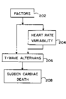
Figure 2A is a block diagram illustrating the diagnostic principles of
the present invention. Block 202 represents all factors which affect the
electrical function of the heart (e.g., drugs and/or diseases). Block 204
represents increased heart rate variability resulting from the factors of block
202. Block 206 represents alternation of the amplitude of the T-wave resulting
from the factors of block 202. Block 208 represents sudden cardiac death
resulting from ventricular fibrillation.
As shown, the factors of block 202 can lead to SCD in block 208 by
two major pathways. The first pathway is from block 202, through block 206,
to block 208. This results from a direct influence of the factors of block 202
on the electrical stability of the heart, manifest in the form of T-wave
alternans. This mode of SCD would occur without a change in heart rate
variability because the nervous system is not involved. A corollary to this is
that a sudden death prediction method which relies solely on heart rate
variability would not be adequate to detect SCD.
The second major pathway from the factors of block 202 to SCD in
block 208 is through blocks 204 and 206. This results from an influence of
the factors of block 202 on the autonomic nervous system. Drugs or heart
disease, for example, can significantly alter neural activity. This will be
expressed as changed heart rate variability. Certain changes in neural activity
which increase sympathetic tone significantly increase T-wave alternans and
therefore could result in SCD.
The inventors have discovered that by combining T-wave alternans
measure and heart rate variability, it is possible, not only to assess risk for
SCD accurately, but also to determine whether a derangement in autonomic
nervous system activity is causal. This has important clinical significance as
it affects both diagnosis and therapy.
WO 94/06350 PCr/US93/08782
2~4~180
-15-
For example, terfenadine (Seldane) is a drug widely employed for the
treatment of sinus problems. It has recently been discovered that, when
terfenadine is used in conjunction with antibiotics, SCD can result.
Terfenadine has no known effects on the autonomic nervous system and
consequently does not affect heart rate variability. However, the drug can
result in alternans in isolated heart preparations and is thus capable of directly
de-stabilizing the electrical activity of the heart. The measurement of T-wave
alternans is therefore an essential approach to detect susceptibility to SCD
induced by a terfenadine/antibiotic combination. This is illustrated in Figure
2B.
For another example, digitalis drugs are the most commonly used agent
for increasing the strength of contraction of ~lise~ed hearts. The drugs
produce this effect by both direct influence on the heart and through alterations
in the autonomic nervous system. In the proper therapeutic range, there is no
significant negative effect on the electrical stability of the heart. However,
when the dose is either too high or the patient's health status changes due to
illness, the same dose of drug may become toxic. It is often difficult to
determine whether a patient is under-dosed or overdosed. By using a
combined alternans/HRV analysis, it would be possible to determine at what
point a neurotoxic influence may lead to alternans and SCD. In particular,
high doses of digitalis decrease vagal tone and increase sympathetic activity,
effects which would be clearly detected in an heart rate variability analysis.
This is illustrated in Figure 2C. This information would be a valuable asset
in the therapeutic management of the patient.
As discussed above, traditional methods of quantifying heart rate
variability or the magnitude of alternans have relied on power spectrum
(Fourier) analysis. However, power spectrum analysis is not capable of
tracking many of the rapid arrhythmogenic changes which characterize T-wave
alternans and heart rate variability. In the preferred embodiment, the present
invention utilizes complex demodulation to analyze heart rate variability and
T-wave alternans.
~,14S~ PCr/US93/08782
-16-
METHOD OF THE INVENTION
The method of the present invention for analyzing an ECG is now
discussed with reference to Figures 3-5.
An ECG signal Cont~ining a plurality N of R-R intervals is sensed from
a patient in real time at step 302. The preferred method of non-invasively
sensing the ECG signal is discussed in detail below. Because the body is akin
to a dipole, a large DC component will be present in the sensed ECG. This
DC component is removed at step 304 with a high-pass filter prior to
amplification of the ECG signal at step 306. The amplifled ECG signal is then
low-pass filtered at step 308 to limit the signal bandwidth before it is digitally
sampled at step 310. The digitized data may then be stored on a magnetic or
optical storage device at step 312. Finally, the digitized ECG data is
dynamically processed at step 314 to: (1) produce an estim~tion of alternans
amplitude and (2) estimate the magnitude of discrete spectral components of
heart rate variability to determine the sympathetic and parasympathetic
influences on cardiac electrical stability.
As an alternative to this real-time signal pre-processing, the ECG signal
may be retrieved from the storage device (step 312) and processed (step 314)
at a later, more convenient time.
Processing step 314 involves two independent computations: alternans
processing and heart rate variability processing. Each is discussed in detail
below.
T-WAVE ALTERNANS
The analysis of alternans at step 314 is described in detail with
reference to Figure 4. At step 404, the apex of each R-wave in the signal data
for each of the N beats is located by fmding the peak amplitudes in the
digitized signal. Premature beats are removed at step 406 by comparison of
each R-R interval with fixed criteria. At step 408, a portion of the ECG
corresponding to an estim~t~d location (with respect to R-wave 106) of T-wave
110 is identified.
WO 94/06350 PCrtUS93/087g2
21~I8~ ~
-17-
At step 410, the T-wave 110 and 112 portion of the ECG signal is
partitioned into "B" time divisions, where "B" may include a single digital
sample or a plurality of samples. The area between the ECG and the
isoelectric baseline is computed for each time division, at step 412, by
5 summing the areas of all samples in the time division. Then at step 414, "N"
s~lcces~ive beats (e.g., from control through release in the animal experiments
discussed below) are sequenced into a time series for each of the "B" time
divisions: (X(n), n = 1,2,...N).
A high-pass filter is used for detrending the time series at step 416 to
10 remove the effects of drift and DC bias (e.g., high-pass filtering removes the
large low-frequency variation in T-wave area that occurs during occlusion of
a coronary artery). A cleaner signal is then available for dynamic estimation,
which is performed at step 418 to estimate the amplitude of alternation for
each time series.
The estimation of step 418 may be performed via several dynamic
methods. By "dynamic" method, it is meant any analytical process sufficiently
rapid to track (i.e., estim~te) transient changes such as those which occur in
alternans amplitude in response to physiologic and pathophysiologic processes
triggering arrhythmias. These include, for example, enhanced neural
20 discharge, acute myocardial ischemia and reperfusion. A "dynamic" method
should be able to track alternans from as few as approximately ten heart beats
(or less). This precludes analytic processes (e.g., Fourier power spectrum
analysis) which require stationarity of data for several minutes. Specific, but
not exclusive, examples of methods for dynamic estimation include:
(a) Complex Demodulation,
(b) Estimation by Subtraction,
(c) Least Squares F.stim~tion,
(d) Auto-Regressive (AR) Estimation, and
(e) Auto-Regressive Moving Average (ARMA) Estimation.
W O 94/06350 ~ PC~r/US93/08782
18-
(A) COMPLEX DEMODULATION
Complex demodulation is the preferred method of dynamic estim~tion
of the beat-to-beat alternation in the amplitude of each time series. Complex
demodulation is a type of harmonic analysis which provides a continuous
5 measure of the amplitude and phase of an oscillation with slowly ch~nging
amplitude and phase. It detects features that might be missed or
misrepresented by standard Fourier spectral analysis methods which assume
stationarity of data.
By definition, alternans is a periodic alternation in the T-wave. The
10 magnitude of alternans, however, changes slowly during a coronary artery
occlusion and more rapidly during release, making it quasi-periodic. As such,
it must be represented by a sinusoid with slowly varying amplitude, A(n), and
phase, ~(n):
X(n) = A(n) cos[2~fALT + ~(n)] E~q. (1)
where: X(n)= the data sequence with alternation in its
amplitude
fA~T = alternation frequency (Hz). It should be noted
that this frequency is half of the heart rate.
Using the identity
ejX + e jX Eq. (2)
the equation for X(n) can be rewritten as
X( ) A( ) (ej2~f~ln ej~n + e-j2~f,,~l,, e j,~,~ Eq (3)
The method of complex demodulation requires multiplying this time
series X(n) by two times a complex exponential at the alternans frequency [to
produce Yl(n)] and then filtering the result to retain only the low frequency
term Y2(n) as follows:
WO 94/06350 . PCr/US93/08782
-19- 2~ ~5~
Yl(n) = X(n) x 2e~~ ~fA~In Eq (4)
= A(n) [ej~(n) + e j4~f~Tn - i~(n)]
Y2(n) = A(n) ej~(n) Eq. (5)
The amplitude and phase of the alternans is then found from the filtered
signal, Y2(n), as follows:
A(n) = ¦ Y2(n) 1
= magnitude of Y2(n) EA~. (6)
= ~/Re[Y2(n)]2 + Im[Y2(n)]2
~(n) = phase of Y2(n)
Im[Y2(n)] Eq. (7)
= arctan
Re[Y2(n)]
where: Im and Re refer to the imaginary and real parts of Y2
For a more detailed discussion of complex demodulation, see Fourier
S Analysis of Time Series: An Introduction, by Peter Bloomfield, John Wiley &
Sons: New York, pp. 118-150; which is incorporated herein by reference.
(B) ESTIMATION BY SUBTRACTION
The subtraction method of dynamic estimation is an alternative which
may be substituted for complex demodulation. The subtraction method
10 involves subtracting the area of each time division (n) of an R-to-R intervalfrom the area of the corresponding time division of a subsequent (n + 1), or
- alternatively, a previous (n-1) R-to-R interval to form a new time series Y(n)
representing the magnitude of alternans. Because this difference series Y(n)
may be positive or negative, the absolute value or magnitude of Y(n) is used
15 for the magnitude A(n). That is:
Y(n) = X(n) - X(n~ . (8)
Wo 94/06350 ~ PCr/US93/0878
A(n) - I Y(n) I Eq (9)
= magnitude of alternans
Some errors may be introduced into this estimate due to the slowly
varying increase in magnitude of the T-wave size at the start of a coronary
occlusion and the reduction in size following the occlusion. Also, some T-
wave variation due to respiration is expected. Therefore detrending the
5 sequence X(n) using a high pass digital filter. or equivalent, improves the
estim~te by removing the effects of T-wave size changes. Also, averaging M
samples together, where M is the number of beats occurring during a single
respiratory cycle, aids in eliminating the respiratory effects on the estimate.
Alternatively, the digital filter may remove both trends and respiratory changes10 if the respiration frequency is sufficiently different from the heart rate, so that
the filtering does not alter the magnitude of the alternans estim~te.
(C) LEAST SQUARES ESTIMATION
The least squares estim~tion, which also turns out, in this case, to be
the maximum likelihood estim~te for estim~ting sinusoid amplitude in white
15 noise, is a second alternative which may be substituted for complex
demodulation to calculate a new sequence which is a dynamic estimate of the
amplitude of alternans. Least squares estim~tion of the amplitude of alternans
A(n) for the data sequence X(n) is derived as follows.
Assume for M points (e.g., 5 to 10 cardiac cycles) that:
X(n) = A cos(2~f,~LTn) + N(n) Eq~. (10)
where: N(n) represents additive noise
In order to minimize the noise term and estimate the alternans component,
create a new function T(A), where:
~j=n [X(j) ~ A CoS(2 JCfALT~)]2 E~. (11 )
W O 94/06350 ~ 8 ~ PC~r/US93/08782
-21-
T(A) represents a measure of the difference between the model and the data.
The best alternans magnitude estimate results if T(A) (i.e., the noise term) is
minimized. To minimize T(A), take the derivative of T(A) with respect to A
and set it equal to zero:
Eq. (12)
-- = --2 x ~j ~cos(2~f,~LT~ tx(i) - A COS(2~f,~TJ~]} =
5 Next, solve this equation for A(n) (shown simply as "A" above) and take the
absolute value of the result to yield the least squares estimate of the magnitude
of the alternans:
Eq. (13)
A(n) = -- ¦ ~j [X~ COS(2~fALTJ~]¦
(D) AuTo-REGREsslvE_sTIMATIoN (AR)
Auto-Regressive (AR) Fctim~tion is a third method of dynamic
10 estimation which may be substituted for complex demodulation. AR
estimation models the alternans as follows:
Eq. (14)
X(n) = - ~k ~ [a(k) x X(n - k)] + u(n)
In this model, "P" is the number of auto regressive coefficients chosen for the
estimation. u(n) represents noise and accounts for the imperfect fit of the
estimation. The method of estim~ting the amplitude of alternans A(n) for the
~ 4~ 22- PCr/US93/08782
data sequence X(n) first involves calculating a matrix of co-variance
coefficients c(i,k) according to the following formula:
Eq. (lS)
c(i,k) = 1 ~j'nM+pl [X(l - i) X X(/ ~ k)]
where: â = the best estim~te of the true value of "a"
P = the number of auto regressive coefficients "â"
M = the number of cardiac cycles
The co-variance coefficients are then used to form "P" auto regressive
coefficients "â" as follows:
Eq. (16)
â(l) c(1,1) c(1,2) . . . c(ljD)~I c(1,0)
â(2) c(2,1) c(2,2) . . . c(2,P) c(2,0)
â(P) c(P,l) c(P~2) . . . c(PjD) c(P,0)
The estim~te of the alternans magnitude is then given by:
Eq. (17)
A(n) = ~2 _ 2
1 - ~ nP i â(n) e ' f~Tn
where: ~2 = C(O,O) + ~P 1 â(n) c(O,n)
For a more detailed discussion of auto-regressive estimation, see
10 Modern Spectral Estimatlon: Theory and Applications, by Steven Kay,
Prentice Hall, 1988, pp. 222-225; incorporated herein by reference.
(E) AuTo-REGREssIvE MOVING AVERAGE (ARMA) ESTIMATION
Auto-Regressive Moving Average (ARMA) F.ctim~tion is yet another
dynamic method which may be substituted for complex demodulation. ARMA
WO 94/063S0 2 1 ~ 5 ~ 8Q PCI/US93/08782
-23-
estimation involves modeling the alternans with a data sequence X(n) as
follows:
Eq. (18)
X(n) = ~ ~ [a(k) x X(n - k)] + ~ O [b(k) x u(n - k)]
Note that this equation is similar to the model of X(n) according to the AR
method, however, additional coefficients "b(k) " have been added to the model .
5 These coefficients are n~cess~ry when the spectrum of the data has contours
which are more complex than just spikes due to alternans and respiration
periodicities. Let "â" and "6" be the best estimates of "a" and "b". The auto
regressive coefficient estim~tes are found by performing Newton Raphson
Iteration to find the zeros of:
Eq. (19)
( ~ a ) ( ~ b )
10 This minimizes the error function:
Eq. (20)
Q(a,b) = r I I(f) IA(l)l df
where~ = M ¦ ~M-ol X(n) e j2~¦2
A(f) = 1 ~ ~=1 a(k)e j2.~fl~
B(~ k o b(k)e -j2T~flC
W0 94/06350 2 ~ 8 a PCrJUS93/0878
-24-
The estimate of the alternans magnitude is then given by:
Eq. (21)
a2 ~1 b(k) e j2
1 - ~k 1 â(k) e j2~f~
where: ~J2 = Q( â,b )
For a more detailed discussion of auto-regressive moving average
estimation, see Modern Spectral Estimation: 17.eory and Applications, by
Steven Kay, Prentice Hall, 19887 pp. 309-312; incorporated herein by
5 reference.
The resultant time series A(n), representative of the magnitude of
alternans, which is produced in step 418 (by one of the dynamic methods set
forth above), may then be analyzed for diagnostic purposes. This may include
producing a surface plot as shown in Figures 1 l(a)-(c) (described below).
It will be understood by one skilled in the art that the various steps of
filtering set forth above may be performed by analog or digital means as
discussed below. It will further be understood that each of the various
filtering steps may be modified or eliminated from the method, if desired.
Note, however, that detrending is particularly important for the Least Squares
15 F.stim~te Method.
Elimination of the various filtering steps will, of course, lead to a
reduction in clarity and will add corruption to the sought after signals. The
amount of corruption will depend on the amount of noise present in the
specific data. The noise sources sought to be filtered include: white noise,
20 respiration induced electrical activity, premature beats, slowly varying trends
present in the area under the ECG waveforms, and other miscellaneous noises.
WO 94/06350 ~ 1 8 ~ PCr/US93/08782
-25-
HEART RATE VARIABILrrY
The analysis of heart rate variability at step 314 is described in detail
with reference to Figure 5. At step 504, the apex of each R-wave in the
signal data for each of the N beats is located by finding the peak amplitudes
5 in the digitized signal. At step 506, the R-R intervals (time) between
successive R-waves is computed. Premature beats are then removed at step
508 by comparing each R-R interval with fixed criteria.
At step 510, a time series of R-R interval data is formed by listing the
R-R interval times in order. At step 512, a second time series or sequence
10 (Rt), whose points are 100 msec apart and whose values are the R-R intervals
present at that time, is formed along the same time line. For example, if the
R-R interval data for a certain ECG signal has the values:
300 msec, 350 msec, 400 msec .....
then the series (Rt,t) would become:
(300,0), (300,100), (300,200), (350,300), (350,400), (350,500),
(350,600), (400,700), (400,800), (400,900), (400,1000) ....
At step 514, the sequence (Rt) is filtered to remove any low frequency
trends. A cleaner signal is then available for dynamic estimation, which is
performed at steps 516 and 522 to estimate the magnitude of discrete spectral
20 components of heart rate to determine the sympathetic and parasympathetic
influences on cardiac electrical stability. This dynamic estim~tion at steps 516and 522 is performed using similar methods (except for Estimation by
Subtraction) to those discussed above with respect to analysis of alternans at
step 418.
Specifically7 the estimation at steps 516 and 522 may be performed via
Complex Demodulation, Auto-Regressive (AR) Estimation, Auto-Regressive
Moving Average (ARMA) Estimation, or other time domain methods.
Traditional power spectrum (Fourier) analysis may be used, however, it is not
recommended because it will produce inferior results and some data (e.g.,
rapid changes in heart rate) may be lost.
Complex demodulation is the preferred method of demodulating heart
rate variability. Complex demodulation of heart rate variability is performed
Wo 94/06350 PCr/US93/08782
26-
as follows. At step 516, the sequence (R) (from step 514) is multiplied by 2
e~j2~ , at f z 0.10 Hz to yield the low frequency component of heart rate
variability. "n" is the index of the data point in sequence (R,). In parallel
with the computation of the low frequency component of heart rate variability
5 at step 516, the high frequency component of heart rate variability is computed
at step 522 by multiplying the sequence (R~ by 2 e~j21r~), at f ~ 0.35 Hz
(i.e., a frequency close to the respiration frequency). The low frequency
component of heart rate variability is then low pass filtered (e.g., roll-off
frequency ~ 0.10 Hz) at step 518. The high frequency component of heart
10 rate variability is low pass filtered (e.g., roll-off frequency z 0.15 Hz) at step
524. It should be noted that low pass filtering (steps 518 and 524) is part of
the method of complex demodulation (steps 516 and 522).
The magnitude of the high frequency (e.g., ~ 0.35 Hz) component of
heart rate is indicative of parasympathetic activity. The magnitude of the low
15 frequency (e.g., z 0.10 Hz) component of heart rate, however, is affected by
both sympathetic and parasympathetic activity. Therefore, to discern the
influence of the sympathetic nervous system, the low frequency (LF)
component of heart rate (from step 518) is divided by the high frequency (HF)
component of heart rate (from step 524) at a step 520 to produce a ratio
20 (LF/HF). This ratio is indicative of the ratio of sympathetic activity to
parasympathetic activity and can thus be used to assess sympathetic activity.
Ratioing low and high frequency components of heart rate to estimate
sympathetic activity is further described in M. Pagani, et al., "Power Spectral
Analysis of Heart Rate and Arterial Pressure Variabilities as a Marker of
25 Sympatho-Vagal Interaction in Man and Conscious Dog, " Circulation
Research, Vol. 59, No. 2, August 1986, pp. 178-193, incorporated herein by
reference.
Steps 516,518 and 522,524 of the method described above detect heart
rate variability using the method of complex demodulation. Analysis of heart
30 rate variability using the method of complex demodulation is further described
in Shin et al., discussed above.
W O 94/06350 PC~r/US93/08782
5,1 8 ~
-27-
APPARATUSOFTHEINVENTION
The preferred embodiment of the apparatus of the invention is
described with reference to Figures 6 and 7. Steps 304-308 of the method
may be performed using a conventional ECG machine or may be performed
using dedicated hardware. Similarly, steps 312 and 314 may be performed on
a general purpose computer or may performed by dedicated hardware.
In the preferred embodiment, the invention is carried out on a heart
monitoring unit (HMU) 600, shown in Figure 6A. HMU 600 includes ECG
sensing leads 601, an ECG detector and pre-processor 602 and an ECG
processing system 604. ECG detector and pre-processor 602, shown in
greater detail in Figure 6B, includes a high-pass filter 6022, a pre-amplifier
6024, and a low-pass filter 6026. ECG sensing leads (i.e., electrodes) 601
provide a signal from a patient directly to high-pass filter 6022.
In an alternate embodiment, ECG detector and pre-processor 602 is a
conventional ECG monitoring machine.
Referring now to Figure 6C, ECG processing system 604 is described.
ECG processing system 604 includes a programmed microcomputer 6040
equipped with an analog-to-digital (A/D) conversion board 6050. The steps
of the method are performed using a software program written in C
Progr~mming language. The program follows the steps set forth above. It is
believed that any skilled programmer would have no difficulty writing the code
necessary to perform the steps of this invention.
Microcomputer or computer platform 6040 includes a hardware unit
6041 which includes a central processing unit (CPU) 6042, a random access
memory (RAM) 6043, and an input/output interface 6044. RAM 6043 is also
called a main memory. Computer platform 6040 also typically includes an
operating system 6045. In addition, a data storage device 6046 may be
included. Storage device 6046 may include an optical disk or a magnetic tape
drive or disk.
Various peripheral components may be connected to computer platform
6040, such as a terminal 6047, a keyboard 6048, and a printer 6049. Analog-
to-digital (A/D) converter 6050 is used to sample an ECG signal. A/D
WO 94/06350 ~ PCr/US93/0878
-28-
converter 6050 may also provide amplification of the ECG signal prior to
sampling.
Figure 7 shows the preferred embodiment of HMU 600. The system
includes 16 channels to allow simultaneous monitoring of a plurality of ECG
leads. High-pass filters 704, pre-amplifiers 706, and low-pass filters 708
perform steps 304, 306 and 308, respectively. High-pass filters 704 have a
0.01 Hz roll-on. Low-pass filters 708 have a 50 Hz bandwidth.
A personal computer 710 includes an A/D converter (with
programmable gain), a printer 714, a re-writable optical disk 716, and a color
monitor 718. The program which runs on computer 710 is preferably menu-
driven. A sample menu is shown on monitor 718.
The menu-driven program may take, as input, information on a
patient's age, sex, medical history, and heart rate. This information could
then be used to select a range of standard indices (~1iscu~sed below) to be usedfor comparison. The menu program would further allow the clinician/operator
to select the A/D sampling rate, the number of ECG channels to monitor, and
the gain of the A/D converter prior to commencing data collection.
Thereafter, the clinician/operator could manually control removal of trends
and premature beats prior to performing the dynamic analysis of alternans and
heart rate variability.
Features of the menu-driven program may include selecting the method
of dynamic analysis to be used and selecting the results to be displayed. For
example, the clinician/operator may desire to view the ECG waveforms, the
time series data (e.g., for each bin of the T-wave both before and after
detrending for the alternans analysis; or for the R-R intervals in the HRV
analysis), or the actual estim~te data (e.g., alternans magnitude, HRV high
frequency component, HRV low/high frequency component ratio).
W O 94/06350 PC~r/US93/08782
5~
-29-
AN1~AL STUDY FOR ALTERNANS ANALYSIS
Animal studies were conducted by the inventors at Georgetown
University School of Medicine in Washington, D.C. Sixteen adult mongrel
dogs (20 to 30 kg) of both sexes were studied in accordance with the standards
5 of the scientific community. The animals were pre-medicated with morphine
sulfate (2 mg/kg, subcutaneously) and anesthetized with alpha-chloralose (150
mg/kg, intravenously), with supplemental doses of alpha-chloralose (600 mg
in 60 ml saline) as required. A left thoracotomy was performed via the fourth
intercostal space.
A Doppler flow probe was placed around the left anterior descending
(LAD) coronary artery and occlusions were performed using a 2-0 silk snare.
Aortic blood pressure was measured with a Gould-Statham P50 pressure
transducer. The ECG was obtained using a 7 French USCI quadripolar
catheter with an inter-electrode ~ist~nre of 10 mm and an electrode width of
2 mm. The catheter was positioned in the apex of the left ventricle via a
carotid artery to coincide with the ischemia. This catheter placement was
found to produce optimal ECG sensing.
Bipolar ECG's were obtained with the negative pole being the second
electrode of the catheter and the positive pole being a needle-electrode placed
transcutaneously in the lower left hip region. A pigtail pressure catheter was
positioned to monitor left ventricular (LV) blood pressure. The area under the
LV pressure pulse of successive beats was analyzed using the technique of
complex demodulation. No evidence of mechanical alternans was found. The
electrocardiographic and hemodynamic data were continuously recorded on a
Thorn EMI FM tape recorder (45 to 50 db S/N ratio, bandwidth of each
channel 0 to 625 Hz). Arterial blood pH, pC02, and p02were monitored using
an Instrumentation Laboratory 1304 blood gas analyzer and were maintained
within physiologic ranges by adjusting ventilation parameters of the Harvard
respirator.
A bilateral stellectomy was performed to interrupt sympathetic neural
input to the heart. This was accomplished by removal of the right stellate
ganglion via the right second interspace and by sectioning the preganglionic
WO 94/06350 PCr/US93/08782
S~3 ~
-30-
fibers and the caudal end of the left ganglion through the left thoracotomy.
The ansae subclavia were left intact to permit pacing of the heart at a rate of
150 beats per minute. Pacing was accomplished by delivering electrical
stimuli of 1.5 to 2 mA of 5 ms duration at a frequency of lOHz to the nerves
5 with a Grass S44 stimulator and an SIU7 stimulus isolation unit.
At the end of each experiment, the taped data was low-pass filtered to
limit the signal bandwidth to 50 Hz. The data was then digitized at 500
samples per second, with a Compaq 386 computer equipped with a Metrabyte
DAS-20 A/D conversion board, and stored on an optical disk. The apex of
10 each R-wave for each of the N beats was then located by finding the peak
amplitudes in the digitized signal. Each beat was indexed by n from 1 to N.
The R-R interval was employed to sort out and remove premature beats which
could introduce artifactual spikes. The period from 60 to 290 ms following
the apex of each R-wave was determined to coincide with the location of the
15 T-wave. This period was divided into bins 10 ms wide for each successive
beat, and the area between the ECG and the isoelectric baseline was computed
for each 10 ms interval. N successive beats from control through release were
then sequenced into a time series for each of the 23 10-ms bins: (X(n), n =
1,2,...N). A sixteenth order Butterworth filter was used for both detrending
20 and demodulating to remove the large low-frequency variation in T-wave area
that occurs during occlusion and to leave a cleaner signal for spectral
estimation.
Detrending was performed by low-pass filtering each time series with
the Butterworth filter and then subtracting the result from the original time
25 series to achieve a high-pass filtering function. To obtain estim~tes of the
magnitude of beat-to-beat alternation in the amplitude of each of these twenty-
three time series, complex demodulation (as set forth above) was used.
The effects of LAD coronary artery occlusion and reperfusion on T-
wave alternans were tested before and after sympathetic denervation and
30 stimulation. Baseline data was obtained for four minutes, the artery was
occluded for eight minutes followed by abrupt release (reperfusion) and a 30-
WO 94/06350 PCr/US93/0878'
-31-
minute rest period. As set forth above, heart rate was m~int~ined constant by
atrial pacing at 150 bpm during assessment of the magnitude of alternans.
In eight dogs, a preconditioning occlusion was followed by a control
occlusion with nerves intact. The occlusion-release sequence was repeated
5 after stellate ganglion ablation.` Finally, the left stellate ganglion was
stimulated two to three minutes prior to occlusion, during the second and fifth
minutes of occlusion, and during reperfusion. In the second group of eight
dogs, the order of interventions was changed to rule out sequence-related error
by omitting the occlusion with nerves intact.
Figures 8(a)-10(a) show, respectively, an electrocardiogram recorded
within the left ventricle before, during, and after coronary artery occlusion ina single representative animal. Figures 8(b)-10(b) show superimposition of six
successive beats. Prior to occlusion (Figure 8), the T-waves of each
succeeding beat are uniform. After four minutes of coronary artery occlusion
15 (Figure 9), there is marked alternation of the first half of the T-wave,
coinciding with the vulnerable period of the cardiac cycle. The second half
of the T-wave remains uniform. After release of the occlusion (Figure 10),
alternans is bidirectional, with T-waves alternately inscribed above and below
the isoelectric line.
Coronary artery occlusion and reperfusion both resulted in significant
increases in the magnitude of beat-to-beat alternation in T-wave amplitude.
Figure 11 shows a surface plot display derived by complex demodulation of
the T-wave of the electrocardiogram before, during, and after coronary artery
occlusion in eight dogs with intact cardiac innervation (Figure 11(a)); after
25 bilateral stellectomy in six dogs (Figure 1 1 (b)); and during 30 sec of
stimulation of the ansa subclavia of the decentralized left stellate ganglion ineleven dogs (Figure 11(c)).
The increase in alternans was evident within two to three minutes of
occlusion and progressed until the occlusion was terminated at eight minutes.
30 Upon reperfusion, there was an abrupt increase in alternans which lasted lessthan one minute. A remarkable feature is that the pattern of alternation during
WO 94/06350 PCr/US93/08782
,;
;S~ 32-
reperfusion was bi-directional, with T-waves occurring alternately above and
below the isoelectric line (Figure 10).
The time course of onset and offset of T-wave alternans during the
occlusion-release sequence coincides with the spontaneous appearance of
5 m~lign~nt tachyarrhythmias including ventricular fibrillation. Figure 12 showsa correlation between the occurrence of spontaneous ventricular fibrillation andT-wave alternans in ten dogs. Dogs which fibrillated exhibited a rapid rise in
alternans within the hrst three or four minutes of occlusion and this change
was significantly more marked than that observed in animals which survived
10 the entire occlusion-release sequence (*=p<0.001. Values are means +
S.E.M.). The results were analyzed using a one-way ANOVA with Scheffé
correction for multiple comparisons. In both groups, the control values did
not differ significantly from the normal distribution by the Kolmogorov-
Smirnov test.
lS It is noteworthy that alternans is marked, though short lasting, duringreperfusion. This transient period of heightened vulnerability to fibrillation is
thought to be due to liberation of washout products of cellular ischemia. The
differing mechanisms responsible for vulnerability during occlusion and
reperfusion may account for the contrasting alternation pattern in T-wave
morphology.
The studies demonstrate that the sympathetic nervous system exerts a
prominent effect on T-wave alternans, a finding which is consistent with its
established arrhythmogenic influence. During coronary artery occlusion,
stellectomy (Figure 11 (b)) reduced alternans during the early phase of
occlusion [from 15.8 + 6.6 at 4 minutes during control to 4.7 + 1.0 mV x
ms (means t S.E.M., p<0.05)], coinciding with the time when neural
activity is high in intact ~nim~ls. However, later in the occlusion, extra-
adrenergic factors may play a role.
Sympathetic neural influences during the reperfusion phase also appear
to be tracked reliably by the present techniques. It was observed that stellate
ganglion ablation increased T-wave alternans during reperfusion [from 19.8
t 3.0 to 29.8 t 3.3 mV x ms (p<0.02)~. This concurs with a previous
WO 94/06350 PCr/US93/08782
~ 33 2~f 8-~
study indicating that stellectomy enhances reperfusion-induced vulnerability to
fibrillation. Stellate ganglion stimulation restored the magnitude of alternans
to a value which was not statistically different from pre-denervation levels.
The link between alternans and vulnerability is underscored by the
S finding that alternans coincides with the established timing of the vulnerableperiod in the cardiac cycle. Superimposition of s~ccessive beats indicates that
alternation is restricted to the first half of the T-wave (Figures 8(b)-10(b)).
This relationship remained constant in all ~nim~ls studied under the changing
conditions of sympathetic nervous system stimulation or denervation.
10 AN]MAL STUDY FOR HEART RATE VARL~BILITY ANALYSIS
An additional animal study conducted by the inventors was performed
to verify the correlation between heart rate variability and alternans. This
additional study was performed substantially as set forth above. Six adult
mongrel dogs were used. LAD occlusion for ten minutes was followed by
15 abrupt release. T-wave alternans appeared within three minutes of occlusion
and increased to 8.97 + 1.58 mVolts-msec by the fourth minute coinciding
with maximum changes in parasympathetic (HF) activity and in the ratio of
sympathetic to parasympathetic (LF:HF) activity. This is illustrated in Figure
13, where 1302 represents parasympathetic activity (HF component) and 1304
20 represents the ratio of sympathetic to parasympathetic activity (LF:HF ratio).
As can be seen from inspection, sympathetic activity increases during
occlusion while parasympathetic activity decreases. At reperfusion, there is
no change in autonomic activity.
It is important to note that these observations concur precisely with
25 previous studies in which nerve activity to the heart was measured using
recording electrodes and vulnerability to ventricular fibrillation was assessed
by programmed cardiac electrical stimulation. In these experiments, it was
shown that a major increase in sympathetic activity corresponded to increased
susceptibility to ventricular fibrillation. See F. Lombardi, R.L. Verrier, B.
30 Lown, "Relationship between Sympathetic Neural Activity, Coronary
Dynamics, and Vulnerability to Ventricular Fibrillation During Myocardial
W O 94/06350 PC~r/US93/08782
-34-
Ischemia and Reperfusion," American Heart Journal, Vol. 105, 1983, pp.
958-965. A major advantage of the method of the invention is that
information derived in such previous invasive studies can be obtained
completely from the body surface ECG by combining heart rate variability and
T-wave alternans measurements.
CLINICAL APPLICABILITY
An ECG suitable for the analysis of heart rate variability is easily
measured using standard surface electrode configurations. However, alternans
are more difficult to sense. AS discussed above, the inventors have discovered
10 that positioning the ECG sensing electrode into the apex of the left ventricle
produces an optimal ECG signal for sensing alternans. This intracavitary
electrode placement, however, requires invasive and hazardous procedures
such that its clinical, diagnostic applicability is limited. What is needed is amethod for sensing T-wave alternans non-invasively on the surface of the
body.
Before discussing sensing of the electrical activity of the heart, it is
helpful to understand a few basic principles. The electrical signals that are
sensed as an ECG include electrical currents that flow through the body as a
result of depolarization and repolarization of the myocardial cells. This
electrical activity may be sensed as a voltage between areas of the body (e.g.,
between the chest proximate the heart and an arm or leg).
Theoretically, the voltage "V" at a position (xp,yp,zp) due to a charge
"q" at (Xj,yj,zk) is given by the following equation:
V = q -- Vrcf
4~1(xp-xi)2+(y _y)2+(Z _z)2 Eq. (22)
where: ~ = permitivity constant
It is assumed that Vref is zero for a unipolar electrode, as discussed below. If
the heart is modelled as a collection of charges then the equation directly
W094/06350 ~51 ~:~ PCr/US93/08782
-35-
below will approximate the voltage Vnom~ sensed by an electrode located at a
point (xp,yp,zp).
Eq. (23)
Vnonn = ~ 2 q
4~\/(xp--x~) + (y _y )2 + (Z _Z )2
Under stable repolarization/depolarization, the charges of the heart will
repeat almost identically to create a stable ECG signal. That is, the charge
5 distribution occurring x msec after the R-wave of one cardiac cycle will be
nearly identical to the charge distribution occurring x msec after the R-wave
of the next cardiac cycle.
When alternans is present, however, the charge distribution will be
modulated such that the charge distribution occurring x msec after the R-wave
10 of successive cardiac cycles can be modeled as a static charge distribution plus
a time varying distribution representing the source of the alternans. This time
varying charge distribution resnlting from alternans may be represented by:
qal~e~ = q Cos(2~f~lLTt)
where: q = the magnihule of the alternahng charge
fALT = alternation frequency (Hz) E~. (24)
t = O, 1, 2, . . . number of beats
Locating the alternans charge at (0,0,0) produces an oscillating voltage
at (xp,yp,zp) as follows:
q cos(2~fOt)
al~cmans
4~x2+y2+zp
where: V,J~ "s = the magnitude of the alternans voltage
measured at a point (xp,y~
Eq. (25)
Wo 94/06350 ~ PCr/US93/0878
-36-
This results in a total voltage at point (xp,y",zp) of:
Vto~l = Vnonn + V~ns Eq. (26)
Vto"" consists of an alternating component plus a constant component. To
maximize the amount of alternating component detected, (xp,yp,zp) must
approach (0,0,0). That is, the detecting electrode must be located as close as
5 possible to the portion of the heart that is generating the alternation signal.
For sensing a normal ECG, limb leads, such as lead Il (left leg with
respect to right arm) can be used. Limb leads, however, are incapable of
detecting the small amplitudes of alternans. Interestingly, the inventors have
discovered that alternans is a regional phenomenon that can be reliably
10 detected via the precordial ECG leads.
By regional, it is meant that the alternans emanate from the injured or
ischemic portion of the heart. For example, it was found that the alternation
signal is strongest in the left ventricle (LV) intracavitary ECG during a left
anterior descending (LAD) coronary artery occlusion. In fact, it was noted
15 that alternation is twelve times greater as recorded from a LV intracavitary
catheter as compared with a right ventricle (RV) intracavitary catheter.
Corresponding to this discovery, the inventors have found that alternans could
be detected in the precordial surface ECG leads corresponding to the injured
portion of the heart. Note that the terms "lead" and "electrode" are used
20 interchangeably herein.
The precordial or chest leads are unipolar electrodes which sense the
ECG signal at the surface of the body. A unipolar electrode senses a positive
electrical current with respect to a neutral lead. The neutral lead is an average
of the voltage on the three standard limb leads: left leg, left arm, and right
25 arm. Ideally, the voltage on the neutral lead is zero.
The location of the precordial leads on the body surface is shown in
Figures 14(a)-(c). The precordial leads include leads Vl through V9 for the
left side of the body and leads VIR through V9R for the right side of the body.
WO 94/06350 PCr/US93/0878'
~ 21~51~
-37-
Note that lead Vl is the same as lead V2R and that lead V2 is the same as lead
VIR .
- The present invention is concerned primarily with precordial leads V,
through V6 because they are closest to the heart and, therefore, yield the
- 5 strongest ECG signals. Figure 15 is a cross-sectional view of the human chest
area 1502 taken along a horizontal axis 1402 shown in Figures 14(a) and
14(b). Figure 15 illustrates the position of the heart 1504 in relation to frontchest wall 1506. The relative positions of precordial leads Vl through V6 and
the corresponding normal ECG signals present at each position are also shown.
Note that lead Vs resides directly over the left ventricular surface.
The inventors have discovered that leads Vs and/or V6 are optimal for
sensing alternans which result from injury to the left ventricle (e.g.,
obstruction of the left anterior descending artery), and leads Vl and/or V2 are
optimal for sensing injuries such as obstruction of the right-side coronary
circulation. Additional precordial leads, such as V9, may be useful for sensing
alternans resulting from remote posterior wall injury. Thus, a physician may
use the complete precordial lead system to obtain precise information
regarding the locus of ischemia or injury.
In order to achieve the maximum sensitivity for alternans sensing,
attenuation by the skin and other body tissues must be reduced. Attenuation
by the relatively large impedance provided by the skin can be overcome by
proper skin abrasion, electrode jelly, or the use of needle electrodes. Further
reduction in attenuation can be achieved by selecting the path of least
resistance to the heart. This includes placing the electrodes between the ribs
rather than over them.
Figures 16(a)-18(a) show continuous ECG tracings obtained
simultaneously from lead 11, lead V~, and a left ventricular intracavitary lead,respectively, during LAD coronary artery occlusion in a chloralose-
anesthetized dog. Figures 16(b)-18(b) show superimposition of the successive
30 beats of Figures 16(a)- 18(a), respectively. Note that the superimposed
waveform from lead Il ~Figure 16(b)] shows no consistently detectable
alternans. Lead Vs [Figure 17(b)~, however, shows marked alternation in the
WO 94/06350 PCr/US93/0878~
S~
-38-
first half of the T-wave, corresponding to the alternation observed in the
intracavitary lead [Figure 18(b)].
Simultaneous comparison of T-wave alternation from lead II, lead V5,
and a left ventricular intracavitary lead during LAD coronary artery occlusion
5 in seven dogs was performed. The results are shown graphically in Figure l9
as a comparison of alternans energy from Leads II and V5 with reference to
the LV intracavitary lead. Exact correlation with the intracavitary lead will
produce a line with a 45 angle. The significant linear relationship (r2 =
0.86) between signals detected in V5 and the LV intracavitary lead indicated
10 that the precordial lead can be used as a surrogate, obviating the need to place
a catheter in the heart. The slope in V5 (0.17 i 0.05) was significantly
greater than in lead II (0.08 + 0.02) (p<0.001). This finding is consistent
with Equation 22 with predicts a linear relationship between the detecting
electrode and the source. As shown, the signal from lead Vs is clearly larger
15 than that of lead II. The intracavitary lead provides a stronger signal than
both lead II and Vs.
Under certain clinical conditions, it may be advantageous to record
alternation from the right ventricle (RV) because of the nature of the cardiac
pathology. For example, under conditions of right heart hypertrophy or other
20 pathology, or right coronary artery disease, the maximum expression of
alternation may be detectable from a catheter positioned in the RV. Since a
catheter can be positioned from the venous side of the circulation, the RV
catheterization is relatively low risk and routine.
In humans, coronary angioplasty was performed in seven patients with
25 greater than 70% stenosis of the LAD coronary artery. The angioplasty
induced a three minute occlusion and reperfusion. Significant increases in T-
wave alternans occurred within two minutes of occlusion and within ten
seconds of release/reperfusion. Alternans occurred predominantly in leads V2,
V3 and V4, corresponding to the sites overlying the ischemic zone. The
30 alternans level was significantly greater than that observed in leads II, Vl, Vs
and V6 and in the Frank leads (see E. Frank, "An Accurate, Clinically
Practical System for Spatial Vectorcardiography," Circulat~on, Vol. 13, 1956,
W O 94/06350 PC~r/US93/08782
39 ~ I ~ 5 ~ ~ q ;
PP. 737-749). Alternation invariably occurred in the first half of the T-wave
as predicted above.
Figure 20 is a surface plot display obtained by the method of complex
demodulation (as set forth above) of the T-wave of the V4 precordial lead
5 during spontaneous heart rhythm in a representative patient during angioplasty.
As can be seen, within two minutes of occlusion there was a significant
increase in T-wave alternans which persisted throughout the occlusion. A
marked surge in alternans upon reperfusion lasted less than one minute.
Figure 21 shows the level of T-wave alternans as a function of
10 recording site in seven patients at three minutes of angioplasty-induced
occlusion and upon balloon deflation. Alternans detected during occlusion in
leads V~, V3 and V4 (the sites overlying the ischemic zone) was significantly
greater than in leads II, Vl, Vs and V6. During reperfusion, alternans levels
in leads Vl-V4 were significantly greater than in leads II, V~ and V6.
CONCLUSION
The ability to sense alternans non-invasively from a surface ECG via
the precordial leads and to track the alternans dynamically yields a major
advance in the quest for predicting SCD. Couple this with an analysis of heart
rate variability to determine the relative influence of the sympathetic and
20 parasympathetic nervous systems, and a diagnostic tool of unprecedented value in the field of cardiology results.
The inventors contemplate producing several indices for the analysis
of the alternans and heart rate variability data. These include a T-wave
alternans index, a heart rate variability index, and a cross-correlation index.
The T-wave alternans index (expressed in mV-msec) may be normalized for
age, gender, medical history, heart size, heart rate, etcetera. Tables of normaldata for the alternans index could be established during exercise or behavioral
stress tests. Monitored values of alternans could then be compared to this
standard index to yield diagnostic information on cardiac health. This includes
detecting and locating ischemic or injured portions of the heart. Rec~llse of
the regional nature of alternans, comparison of the alternans from each
WO 94/06350 PCr/US93/087g~
a
precordial lead with a corresponding standard index value for that lead would
allow an ischemic or injured site to be located without the need for invasive
procedures.
The alternans index may be developed along the lines of arterial blood
5 pressure indexes, for example, where pressure values in excess of
140mmHg/9OmmHg are deemed to be in the range where treatment is
indicated.
The heart rate variability index may be expressed as an HF amplitude
(in milliseconds) and a LF/HF ratio. Normative data may be established for
10 both endpoints. It will be important to establish when sympathetic activity is
excessively high and/or when parasympathetic activity is low.
The cross-correlation index recognizes that a combination of high
degree of alternans and low heart rate variability indicates a condition is which
the heart is particularly prone to ventricular fibrillation. This is based on the
15 fact that lowered heart rate variability indicates high sympathetic and low
parasympathetic activity. It is anticipated that a mathematical function (e.g.,
a product of the alternans and heart rate variability indices, a power function,etcetera) will be developed to produce the cross-correlation index from the
alternans index and the heart rate variability index. Empirical data will be
20 required to establish the precise quantitative relationship between the two.
It is contemplated that the invention will have great utility in the
development of drugs, as their effects on autonomic activity and on the heart
itself can be closely monitored.
It is further contemplated that the heart monitoring unit could be
25 miniaturized and incorporated into an implantable cardioverter/defibrillator
unit to sense alternans and heart rate variability, and then deliver drugs or
electricity to prevent or abort life-threatening rhythms or to revert cardiac
arrest.
Although the invention has been described and illustrated with a certain
30 degree of particularity, it is understood that those skilled in the art will
recognize a variety of applications and appropriate modifications within the
spirit of the invention and the scope of the claims.