Note: Descriptions are shown in the official language in which they were submitted.
~ 4~2~
W o 94/06302 P ~ /IE93/00051
"Method and apparatus for separating meat
from a bone of an animal carcass"
The present invention relates to an apparatus and a method for
separating meat from a bone of an animal carcass, and in
particular, though not limited to an apparatus and a method for
separating meat from the ribs of a carcass side.
In the processing of animal carcasses in a meat factory, it is
necessary to remove the meat from the bones of the animal
carcass, this operation, in general, is referred to as de-boning
the meat. In general, the animal carcass is normally presented
to the operator, normally, referred to as a de-boner in the form
of a half carcass which is commonly referred to as a carcass
side. For convenience, the carcass side is further halved by
cutting the carcass side transversely between a pair of ribs
intermediate the front and rear legs. The two halves thus formed
are referred to as quarters, namely, a front and hind quarter.
To remove the meat from the front and hind quarters, the quarters
are presented to the operator, generally, suspended from a hook
carried on a carrier element which is rollable on an overhead
conveyor track. The operator with a knife, manually cuts and
separates the meat from the bones of the carcass, which include
the spine bone and ribs. In general, it is relatively easy to
cut and separate the meat from the spine bone. However,
considerable difficulty is encountered in cutting and separating
the meat from the ribs. A double membrane which comprises an
inner and outer membrane securely attaches the meat to the ribs.
The inner and outer membranes are secured along join lines which
extend between and parallel to the ribs and define pockets for
accommodating the ribs. The membranes as well as being secured
to each other and to the meat, are also securely attached to the
ribs. In order to remove the meat from a rib, the de-boner must
first of all cut the membranes along each side of the rib, and
then insert a knife between a pair of adjacent ribs and behind
one of the ribs to cut the meat either from the inner membrane or
WO 94/06302 PCr/lE93/00051~
2~4~200
to separate the inner membrane from the rib. This is a
particularly difficult, tedious and time consuming, as well as a
dangerous task, and in many instances, can result in serious
wounds being inflicted on the hands, fingers and other parts of
the body of the operator. Additionally, meat is left behind on
the bones which is wasted.
There is therefore a need for an apparatus and method for
separating meat from a bone of an animal carcass, and in
particular, for separating meat from the ribs of a carcass side.
The present invention is directed towards providing such an
apparatus and method.
According to the invention there is provided apparatus for
separating meat from a bone of an animal carcass, the apparatus
comprising a main support means, a clamp means for holding and
1~ supporting at least a portion of an animal carcass, the clamp
means being mounted on the main support means, a carcass engaging
means for engaging the carcass portion for urging the meat from
the bone, the carcass engaging means being mounted on the main
support means, at least one of the carcass engaging means and the
clamp means being movable relative to the other for urging the
carcass engaging means into engagement with the carcass portion,
and a first drive means for moving one of the carcass engaging
means and the clamp means for engaging the carcass engaging means
with the carcass portion for urging the meat from the bone.
The advantages of the invention are many. The most important
advantage of the invention is that it enables meat to be readily
easily separated from a bone, for example, the ribs of a carcàss
side with minimal manual intervention. Furthermore, the
apparatus according to the invention avoids the need to divide
the carcass side into quarters, which considerably improves the
efficiency with which meat can be removed from the carcass side.
It has also been found that use of the invention enables
W O 94/06302 ~ 2~o
PCT/IE93/OOOSl
considerably more meat to be removed from the ribs of a carcass
side than has been possible heretofore. The ribs are
substantially striped clean of all meat by using the apparatus.
.
In one embodiment of the invention the carcass engaging means is
movable relative to the main support means towards the clamp
means for engaging and urging meat from the bone. Preferably,
the carcass engaging means is movable relative to the main
support means along a path of movement along the bone. This
enables the meat to be continuously removed from the bone.
In another embodiment of the invention a second drive means is
provided for moving the carcass engaging means along the path of
movement along the bone. This feature of the invention provides
a particularly efficient apparatus.
In another embodiment of the invention the carcass engaging means
is movable transversely of the bone from one bone to another
adjacent bone. This feature of the invention enables the
apparatus to handle a relatively large carcass portion, for
example, a carcass side.
Preferably, a third drive means is provided for moving the
carcass engaging means transversely of the bone.
In one embodiment of the invention the carcass engaging means is
carried on one end of an elongated carrier arm, the carrier arm
being pivotal about a main pivot axis at a location spaced apart
from the carcass engaging means for accommodating movement of the
carcass engaging means along the path of movement along the bone.
This feature provides a relatively efficient construction of
apparatus.
In another embodiment of the invention a first mounting means
mounts the carcass engaging means to the main support means, the
carrier arm being pivotally connected to the first mounting means
W O 94/06302 PC~r/IE93/OOOSI -
2 1 4 5 Z ~ a 4
about the main pivot axis.
In another embodiment of the invention the carrier arm is
longitudinally slidable in a housing for accommodating movement
of the carcass engaging means towards the clamp means, the
housing being pivotally connected to the first mounting means
about the main pivot axis. Preferably, the first drive means
moves the carrier arm along its longitudinal axis in the housing.
Advantageously, the second drive means pivots the carrier arm
about the main pivot axis.
In a further embodiment of the invention the first mounting means
is movably mounted to the main support means and is movable
relative to the main support means in a direction parallel to the
main pivot axis for moving the carcass engaging means from one
bone to the next adjacent bone. Preferably, the third drive
means moves the first mounting means in a direction parallel to
the main pivot axis. In one embodiment of the invention the
carrier arm is pivotally mounted in the housing about its
longitudinal axis for altering the disposition of the carcass
engaging means relative to the carcass portion. Preferably, a
fourth drive means is provided for pivoting the carrier arm in
the housing.
Preferably, the carcass engaging means is a carcass engaging
disc. Advantageously, the carcass engaging disc is a circular
disc.
Advantageously, the carcass engaging disc is rotatably mounted
about a rotational axis coinciding with its central axis.
Preferably, the rotational axis of the carcass engaging disc is
disposed relative to the main pivot axis between a position
extending parallel to the main pivot axis and extending at an
angle of 75 to the main pivot axis when the rotational axis and
the main pivot axis lie in a common plane. Advantageously, the
rotational axis of the carcass engaging disc extends at an angle
w O 94/06302 ~ 2 ~ O PCT/IE93/00051
of approximately 30 to the main pivot axis when the rotationa1
axis and the main pivot axis lie in a common plane.
In one embodiment of the invention the main support means
comprises a first support means, the first mounting means being
mounted on the first support means. Advantageously, the first
support means extends in a generally vertical direction, and the
first mounting means is movable in a general vertical direction
relative to the first support means parallel to the main pivot
axis.
In another embodiment of the invention the clamp means is
pivotally connected to the main support means about a first
secondary pivot axis which extends perpendicularly to the main
pivot axis for aligning a bone with the path of movement of the
carcass engaging means. Preferably, the clamp means is pivotally
connected to the main support means about a second secondary
pivot axis perpendicular to the first secondary pivot axis for
aligning the carcass portion with the path of movement of the
carcass engaging means. Advantageously, a second mounting means
is provided for mounting the clamp means to the main support
means about the first and second secondary pivot axes.
Preferably, the main support means comprises a second support
means located rigidly relative to the first support means, the
second mounting means mounting the clamp means to the second
support means. Preferably, the second support means extends in a
general vertical direction.
In one embodiment of the invention the first and second support
means are spaced apart from each other and the clamp means and
the carcass engaging means are located intermediate the first and
second support means.
In another embodiment of the invention the clamp means supports
the carcass portion intermediate the clamp means and the carcass
engaging means. In one embodiment of the invention the carcass
w o 94/06302 PCT/IE93/0005l
2 1 4 ~ 2 ~ ~ 6
engaging means is for engaging a carcass portion adjacent a rib
thereof for urging the meat from the rib.
In another embodiment of the invention the clamp means supports
the carcass portion so that the inner side of the carcass portion
is presented to the carcass engag;ng means.
, :.
In a further embodiment of the invëntion the clamp means supports
the carcass portion with the ribs extending substantially
horizontally, and the main pivot axis extends substantially
vertically. Preferably, the carcass engaging means ruptures a
membrane retaining the meat to the bone. Advantageously, the
carcass engaging means is provided with a cutting edge for
rupturing the membrane.
In one embodiment of the invention the first drive means
comprises a first ram. Preferably, the first ram is an hydraulic
ram.
In another embodiment of the invention the clamp means comprises
an elongated carcass abutting member and a clamping member co-
operating with the carcass abutting member for clamping the
carcass portion to the carcass abutting member. Advantageously,
the carcass abutting member is pivotally connected to the second
mounting means about the first and second secondary pivot axes.
Preferably, the clamp means is for supporting a carcass side.
In another embodiment of the invention a receiving means is
provided on the clamp means for co-operating with an external
conveyor means for receiving a carrier element of the conveyor
means for transferring a carcass portion from the conveyor means
to the clamp means. Preferably, the receiving means is
releasably co-operable with the conveyor means. Advantageously,
a retaining means is provided for retaining a carrier element
located on the receiving means. Preferably, the receiving means
is mounted on the carcass abutting member.
2~52~
W o 94/06302 P ~ /1E93/00051
Additionally the invention provides a method for separating meat
from a bone of a portion of an animal carcass using the apparatus
according to the invention, the method comprising the steps of
supporting the carcass portion in the clamp means, urging the
carcass engaging means into engagement with the meat adjacent the
bone, and further urging the carcass engaging means for urging
the meat from the bone.
In one embodiment of the invention the method further comprises
the step of moving the carcass engaging means along a path of
movement along the bone simultaneously while the carcass engaging
means is being urged against the meat for continuously and
progressively urging the meat from the bone along the length
thereof. In another embodiment of the invention the carcass
engaging means is moved along and adjacent one side of the bone
for urging the meat therefrom.
Preferably, the method comprises the step of urging the carcass
engaging means into engagement with a membrane attaching the meat
to the bone, the carcass engaging means being urged into
engagement with the membrane adjacent the bone.
Advantageously, the carcass engaging means ruptures the membrane
attaching the meat to the bone.
In one embodiment of the invention the carcass engaging means co-
operates with the bone for rupturing the membrane.
In another embodiment of the invention the carcass engaging means
is moved along and adjacent a side of the bone for rupturing a
membrane attaching the meat to the bone.
In one embodiment of the invention the carcass engaging means
engages a double membrane attaching the meat to a rib for urging
the meat from the rib. Advantageously, the carcass engaging
means engages the double membrane adjacent the rib for rupturing
w o 94/06302 PCT/IE93/00051 -
2 ~ ~ ~ 2 Q ~ 8
The invention will be more clearly understood from the following
description of some preferred embodiments thereof given by way of
example only with reference to the accompanying drawings, in
which:
Fig. 1 is a perspective view of apparatus according to the
invention for separating meat from a bone of portion of an
animal carcass,
Fig. 2 is a cross-sectional plan view of the apparatus of
Fig. 1,
Fig. 3 is a front elevational view of portion of the
apparatus of Fig. 1,
Fig. 4 is an end elevational view of the portion of Fig. 3
of the apparatus of Fig. 1,
Fig. 5 is a plan view of the portion of Fig. 3 of the
apparatus of Fig. 1,
Fig. 6 is an end elevational view of another portion of the
apparatus of Fig. 1,
Fig. 7 is a front elevational view of the portion of Fig. 6
of the apparatus of Fig. 1,
Fig. 8 is a front elevational view of the portion of Fig. 6
of the apparatus of Fig. 1,
Fig. 9 is a perspective view of a detail of the apparatus
of Fig. 1,
Fig. 10 is a partly cut-away partly sectional front
21~2~0
W O 94/06302 P ~ /IE93/00051
elevational view of the detail of Fig. 9 of the apparatus
of Fig. 1,
Fig. 11 is a plan view of the detail of Fig. 9 of the
apparatus of Fig. 1,
Fig. 12 is a rear elevational view of another detail of the
apparatus of Fig. 1,
Fig. 13 is a partly sectional end elevational view of the
detail of Fig. 12 on the line XIII-XIII of Fig. 12,
Fig. 14 is an end elevational view of portion of the detail
of Fig. 12,
Fig. 15 is a sectional end elevational view of portion of
an animal carcass side illustrating the operation of the
apparatus of Fig. 1,
Fig. 16 is a perspective view of a section of the carcass
side of Fig. 15 illustrating portion of the apparatus of
Fig. 1 in use,
Fig. 17 is a perspective view of a detail of apparatus
according to another embodiment of the invention for
separating meat from a bone of portion of an animal
2d carcass,
Fig. 18 is an end elevational view of the detail of Fig.
17,
Fig. 19 is a partly sectional plan view of the detail of
Fig. 17, and
Fig. 20 is a cross-sectional end elevational view of the
detail of Fig. 17 on the line XX-XX of Fig. 19.
W O 94/06302 PCT/IE93/00051 ~
2l4S2'~ 10
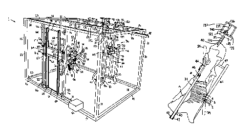
- Referring to the drawings and initially to Figs. 1 to 16 there is
illustrated apparatus according to the invention indicated
generally by the reference numeral 1 for separating meat 2 from a
bone, namely, ribs 3 of portion of an animal carcass, in this
case, a carcass side 4. Before describing the apparatus 1 in
detail, the relevant aspects of the carcass side 4 will first be
described. It is however, expected that those skilled in the art
will be familiar with a carcass side. Referring in particular to
Figs. 7, 15 and 16 amongst other items, the carcass side 4
comprises a spine portion 6 extending substantially the length of
the carcass side 4. The ribs 3 extend from the spine 6. The
meat 2 is retained on the ribs 3 by a double membrane 8 which is
formed by an inner membrane 9 to which the meat 2 is attached and
an outer membrane 10. The membranes 9 and 10 are joined to each
other along longitudinally extending join lines 11 which extend
parallel to and between the ribs 3. Pockets 12 extend between
the join lines 11 for accommodating the ribs 3. Both the inner
and outer membranes 9 and 10, respectively, are relatively,
tightly attached to the ribs 3.
Turning now to the apparatus 1, the apparatus 1 comprises a main
support means, in this case provided by a main support framework
15 of box section steel. The main support framework 15 comprises
a base frame 16 comprising a pair of side members 17 and 18
joined by end members 19 and 20. Four uprights, namely, one pair
of uprights 21 and a second pair of uprights 22 extend upwardly
from the base frame 16 to a top frame 23 having side members 24
and 25 joined by end members 26 and 27. A conveyor track 28
supports roller carrier elements 29 from which the carcass sides
4 are suspended. The conveyor track 28 and carrier elements 29
will be known to those skilled in the art, however, they are
described in more detail below. Each carcass side 4 from which
the meat 2 is to be urged from the ribs 3 is delivered into the
main support framework 15 on the conveyor track 28 through an
input opening 30 formed by the end members 19 and 26 and by the
uprights 21. Each carcass side 4 is delivered from the main
~ W O 94/06302 21 q ~ 2 0 0 PCT/IE93/00051
support framework 15 on the conveyor track 28 through an output
opening 31 formed by the end members 20 and 27 and the uprights
22. First support means is formed in the main support framework
15 by a pair of first support members 33 which extend vertically
between the side members 17 and 24 for a purpose to be described
below. Second support means also for a purpose to be described
below is formed in the main support framework 15 by a vertically
extending second support member 34 extending between the side
members 18 and 25 and secured thereto by brackets 35.
Second mounting means comprising a second mounting assembly
indicated generally by the reference numeral 36 mounts a clamping
means comprising a clamp 37 for receiving and supporting the
carcass side 4 to the second support member 34 while the meat 2
is being separated from the ribs 3. The second mounting assembly
36 will be described in more detail below. The clamp 37 of
stainless steel comprises an elongated carcass abutment member 40
carried on the second mounting assembly 36. A clamping member 41
pivotally connected by a pivot pin 42 to the abutment member 40
and co-operating with the abutment member 40 clamps the carcass
side 4 with the outer side of the carcass side 4 abutting the
abutment member 40. A spine engaging member 44 pivotally
connected to the clamping member 41 by a pivot pin 45 engages the
spine portion 6 of the carcass side 4 for securing the carcass
side 4 against the abutment member 40. A double acting hydraulic
ram 46 is pivotally connected to the abutment member 40 and the
clamping member 41 and operates the clamping member 41 between an
open position disengaged from the carcass side 4 to a closed
position with the spine engaging member 44 tightly engaging the
carcass side 4. A locating member 47 rigidly connected by a pair
of connecting members 49 to the abutment member 40 supports and
locates the carcass side 4 in the clamp 37. The locating member
47 engages the carcass adjacent a shoulder portion 48 thereof.
An elongated carrier arm 50 of stainless steel is longitudinally
slidable and pivotal about its longitudinal axis in a cylindrical
Wo 94/06302 P ~ /IE93/00051
2 ~ ~ S 2 ~ ~ - 12
housing 51 which is in turn mounted to the first support member
33 by a first mounting means provided by a first mounting
assembly 52 as will be described below. A carcass engaging means
comprising a circular carcass engaging disc 54 of stainless steel
is rotatably carried on a spindle 55 located at one end of the
carrier arm 50 for cutting and rupturing the double membrane 8
securing the meat 2 to the ribs 3 of the carcass side 4, and for
urging the meat 2 from the ribs 3. A peripheral cutting edge 56
extending completely around the disc 54 facilitates in rupturing
of the double membrane 8. A first drive means comprising a
double acting first hydraulic ram 57 mounted on the housing 51 by
brackets 53 drives the carrier arm 50, and in turn, the carcass
engaging disc 54 in the directions of the arrows A and B for
urging the carcass engaging disc 54 into and out of engagement
with the carcass side 4, and in particular, into engagement with
the double membrane 8 adjacent the join lines 11. Additionally,
the hydraulic ram 57 urges the carcass engaging disc 54 further
into the carcass side 4 between the ribs 3 for rupturing the
double membrane 8 adjacent the join lines 11 and for urging the
meat 2 from the ribs 3. This is described in more detail below.
The first hydraulic ram 57 comprises a cylindrical housing 58
which is secured to the housing 51 by the brackets 53. A piston
rod 59 extending from the cylindrical housing 58 terminates in a
connecting bracket 60 which is secured thereto and is engaged
with and located at a fixed location on the carrier arm 50 for
sliding the carrier arm 50 in the housing 51 in the direction of
the arrows A and B.
Returning now to the first mounting assembly 52, the first
mounting assembly 52 comprises a carriage 62 which is engagable
with and vertically slidable in the direction of the arrows C and
D between the first support members 33 for providing vertical
movement of the carcass engaging disc 54 substantially
longitudinally relative to the carcass side 4 for moving the
carcass engaging disc 54 from one rib to the next. The carriage
62 comprises a pair of cross members 63 joined by side members 64
o ~
W o 94/06302 PCT/IE93/00051
13
and 65. Bearings 66 rotatable on brackets 67 mounted on the side
members 64 and 65 rollably engage the first support members 33
for locating and guiding of the carriage 62 between the first
support members 33. A pair of drive chains 68 around sprockets
69 and 70 fast on shafts 71 and 72, respectively, are anchored at
their respective ends 73 and 74 by anchor brackets (not shown) to
the cross members 63 of the carriage 62. The shafts 71 and 72
are rotatably mounted in bearings 76 secured to the first support
members 33. Third drive means comprising an hydraulically
powered drive motor 77 illustrated in block representation is
mounted on the side member 17 and drives the shaft 71 for in turn
moving the carriage 62 in the direction of the arrows C and D in
the general vertical direction.
A pair of support arms 80 extending inwardly from the carriage 62
into the main support framework 15 mount the housing 51 and in
turn the carrier arm 50 to the carriage 62, see in particular
Figs. 3 to 5. A spindle 82 extending between and pivotally
mounted in bearings (not shown) in the support arms 80 defines a
main vertically extending pivot axis 83 about which the carrier
arm 50 is pivotal. A mounting bracket 84 extending from the
spindle 82 rigidly connects the housing 51 to the spindle 82. A
second drive means comprising a double acting second hydraulic
ram 85 pivots the housing 51, and in turn, the carrier arm 50
about the main pivot axis 83 for moving the carcass engaging disc
54 in a horizontal arc. Accordingly, when the carcass engaging
disc 54 is in engagement with the double membrane 8 between the
ribs 3, the carcass engaging disc 54 moves along a path of
movement in the direction of the arrows G and H which extends
substantially parallel to the ribs 3, and substantially follows
the natural curvature of the ribs 3. Thus, when the carcass
engaging disc 54 is urged into the meat between the ribs 3 the
double membrane is ruptured along the join line 11 and the meat
is urged from at least one if not two of the adjacent ribs 3 by
the carcass engaging disc 54. The second ram 85 comprises a
cylindrical housing 86 which is pivotally connected by a pair of
W O 94/06302 PCT/IE93/00051 ~
2~4s2Q~
_ 14
pivot brackets 87 to a mounting 88 extending between the support
arms 80. A piston rod 89 extending from the cylindrical housing
86 is pivotally connected to the housing 51 by a pair of pivot
brackets 90.
Returning to the carrier arm 50 and the connecting bracket 60
which connects the carrier arm 50 to the piston rods 59 of the
ram 57, a fourth drive means comprising an hydraulic motor 91
illustrated in block representation is mounted on the connecting
bracket 60 for pivoting the carrier arm 50 about its longitudinal
axis for in turn permitting the disposition, in other words, the
angle of attack of the carcass engaging disc 54 relative to the
carcass side 4 to be altered. Although the connecting bracket 60
is located in a fixed position on the carrier arm 50, the carrier
arm 50 is rotatable in a bearing (not shown) in the connected
bracket 60. Such rigid longitudinal mounting and rotatable
mounting may be achieved in many ways which will be well known to
those skilled in the art. Typically, the bearing (not shown) may
be rigidly located in the connecting bracket 60 and on the
carrier arm 50 by circlips engaging respective grooves in the
connecting bracket 60 and the carrier arm 50. A drive chain 92
around sprockets 93 on the carrier arm 50 and a drive shaft 94 of
the hydraulic motor 91 transmits drive from the hydraulic motor
91 to the carrier arm 50 for pivoting the carrier arm 50 in the
housing 51. In this embodiment of the invention the rotational
axis 95 of the spindle 55 carrying the carcass engaging disc 54
is disposed at an angle of approximately 30 to the main pivot
axis 83 when the spindle 55 and the main pivot axis 83 lie in the
same plane.
Returning now to the second mounting assembly 36 for mounting the
clamp 37 to the second support member 34, the second mounting
assembly 36 comprises an elongated mounting bracket 97 rigidly
secured to the second support member 34, see in particular Figs.
6 to 11. A pair of spaced apart mounting members 98 extend
rigidly from the mounting bracket 97 inwardly into the main
2 ~ Q
W o 94/06302 PCT/IE93/oO05l
support framework 15, and pivotally carry a pair of spindles 99
extending from a carrier housing 100. The spindles 99 define a
vertically extending second secondary pivot axis 102 about which
the clamp 37 is pivotal for aligning the ribs 3 of the carcass
side 4 with the path of movement of the carcass engaging disc 54.
The spindles 99 are welded to and extend from the carrier housing
100 and are pivotally carried in bearings 103 located in the
mounting members 98. A pivot shaft 105 extending from the
abutment member 40 of the clamp 37 defines a horizontally
extending first secondary pivot axis 106. The pivot shaft 105 is
rotatably carried in the carrier housing 100 for pivoting the
clamp 37 about the horizontal first secondary pivot axis 106, for
aligning the ribs substantially horizontally to coincide with the
path of movement in the direction of the arrows G and H of the
carcass engaging disc 54 between the ribs 3.
A fifth drive means comprising a double acting fifth hydraulic
ram 107 mounted between the carrier housing 100 and the abutment
member 40 of the clamp 37 pivots the clamp 37 about the first
secondary pivot axis 106. The stroke of the fifth hydraulic ram
107 is sufficient to pivot the carcass abutment member 40 +/-50
on each side of the vertical. The fifth hydraulic ram 107
comprises a cylindrical housing 108 which is pivotally connected
to the carrier housing 100 by a pair of pivot mounting brackets
109. A piston rod 110 extending from the cylindrical housing 108
is pivotally connected by a pair of pivot mounting brackets 111
to a mounting member 112 rigidly extending from the abutment
member 40.
A sixth drive means, namely, a double acting sixth hydraulic ram
114 connected between the carrier housing 100 and the mounting
bracket 97 pivots the carrier housing 100, and in turn the clamp
37 about the second secondary pivot axis 102. A pair of pivot
mounting brackets 115 pivotally connects a cylindrical housing
116 of the ram 114 to the mounting bracket 97, while a pair of
pivot mounting brackets 117 pivotally connects a piston rod 118
w O 94/06302 PCT/IE93/00051 ~
45?.. ~ 16
of the hydraulic ram 114 to the carrier housing 100.
As can be seen the clamp 37 supports the carcass side 4 within
the main support framework 15 between the abutment member 40 and
the carcass engaging disc 54 carried on the carrier arm 50 so
that the carcass side 4 is supported by the abutment member 40 of
the clamp 37 against the action of the carcass engaging disc 54
rupturing the double membrane 8 and urging the meat away from the
ribs 3.
Returning now to the conveyor track 28, the conveyor track 28
would in general be suspended from the ceiling of a building.
Each roller carrier element 29 comprises a support member 120
depending downwardly and supported on an axle 121 which is
rigidly connected to the support member 120, see Figs. 12 to 14.
A roller 122 is rotatably mounted on the axle 121 for rotatably
carrying the support member 120 on the conveyor track 28. A
guide member 123 rigidly connected to the axle 121 extends
downwardly therefrom and co-operates with the support member 120
for guiding and retaining the roller 122 on the conveyor track
28. A hook 124 is mounted at the lower end of the support member
120 for engaging and supporting a carcass side 4. The conveyor
track 28 extend into the main support framework 15 through the
input opening 30 and the output opening 31.
A receiving means, namely, a track portion 125 is mounted on the
abutment member 40 of the clamp 37 and co-operates with the
conveyor track 28 adjacent the input opening 30 and the output
opening 31 for receiving the carrier elements 29 from, and
delivering the carrier elements 29 onto the conveyor track 28.
In this way a carcass side 4 is conveyed directly from the
conveyor track 28 to the clamp 37. Additionally, the carcass
side 4 when clamped in the clamp 37 is also supported on a
carrier element 29 which is engaged on the track portion 125.
This is described in more detail below.
2~52~0
W o 94/06302 ^ P ~ /IE93/00051
The track portion 125 is releasably engagable and alignable with
the conveyor track 28 to facilitate pivoting of the clamp 37
about the first and second secondary pivot axes 102 and 106
defined by the spindles 99 and the pivot shaft 105, respectively.
Track extensions 128a and 128b are pivotally connected by pivot
pins 129 to the portions of the conveyor track 28 which extends
into the main support framework 15 at the input opening 30 and
the output opening 31, respectively. The track extensions 28 are
pivotal from an aligned position illustrated in Fig. 1 aligning
and connecting the conveyor track 28 to the track portion 125 to
a disengaged position as illustrated by the track extension 128b
in Fig. 12 with the conveyor track 28 disconnected from the track
portion 125 to facilitate pivoting of the clamp 37 about the
secondary p;vot axes 102 and 106. Double acting hydraulic rams
130 pivotally connected to brackets 131 and 132 which extend from
the conveyor track 28 and the track extensions 128, respectively,
pivot the track extensions 128 for respectively connecting and
disconnecting the conveyor track 28 with the track portion 125.
Retaining means for retaining a carrier element 29 located on the
track portion 125 while a carcass side 4 is clamped in the clamp
37 comprises a retaining member 135 of inverted U-shape carried
on a double acting hydraulic ram 136. A mounting framework 137
extending from the track portion 125 carries the ram 136. A
cylindrical housing 139 of the ram 136 is rigidly secured to the
framework 137. The retaining member 135 is secured to a piston
rod 140 extending from the cylindrical housing 139 of the ram
136. The retaining member 135 is operable by the ram 136 between
a retaining position illustrated in Fig. 12 engaging the roller
122 of the carrier element 29 for retaining the roller carrier
element 29 located on the track portion 125 to a released
position illustrated in Fig. 13 with the retaining member 135
raised above the track portion 125 to permit free rolling of the
carrier element 29 along the track portion 125.
Valves (not shown) are provided for supplying hydraulic fluid to
W O 94/06302 PCT/IE93/0005l -
2~4s2~
18
the rams 46, 57, 85, 107, 114, 130 and 136. An hydraulic valve
is also provided for supplying hydraulic fluid to the hydraulic
motors 77 and 91. Such valves and their operation will be well
known to those skilled in the art. In general, it is envisaged
that the valves will be solenoid operated and suitable control
circuitry will be provided for operating the valve. Controls
(not shown) are also provided for operating the valves for
operating the rams and the motors in the appropriate sequence to
operate the apparatus 1. Such controls may be partly manual and
partly automatically operated. However, it is envisaged that the
ram 57 for moving the carrier arm 50 for bringing the carcass
engaging disc 54 into and out of engagement with the carcass side
4 will be manually operated, as will the ram 85 for pivoting the
carrier arm 50 about the main pivot axis 83. The rams 107 and
114 may also be manually operated for pivoting the clamp 37 about
the secondary pivot axes 102 and 106. In all cases, the manual
operation of these rams will be carried out through the valves
associated with the respective rams. It is envisaged that
sensors may be provided on the track portion 125 for sensing when
a carrier element 29 is located beneath the retaining member 135.
The ram 136 for operating the retaining member 135 may be
automatically operable in response to the sensor. The rams 130,
in general, would be operated in response to the sensor. The ram
46 for operating the clamping member 41 may also be operated in
response to the sensor, although as discussed above the ram 46
may also be manually operated. The drive motor 77 may be
manually or automatically operated for moving the carriage 62
upwardly and/or downwardly, as may the motor 91.
In use, a carcass side 4 suspended on a roller carrier element 29
is moved along the conveyor track 28 into the clamp 37. While
the roller carrier element 29 is being moved along the conveyor
track 28 onto the track portion 125, the track extensions 128 are
in the aligned position and the retaining member 135 is in the
released position. On the roller carrier element 29 rolling onto
the track portion 125, and being aligned with the retaining
WO 94/06302 ~ 1 A 5 2 0 0 PCI/IE93/00051
19
member 135, the retaining member 135 under the action of the ram
136 is lowered into the retaining position for retaining the
carrier element 29 located on the track portion 125. The carcass
side 4 is manipulated so that the locating member 47 engages the
5 shoulder portion 48 of the carcass side 4. The clamping member
41 is pivoted by the ram 46 into engagement with the spine
portion 6 of the carcass side 4 for clamping and retaining the
carcass side 4 supported in the clamp 37. The track extensions
128a and 128b are pivoted upwardly into the disengaged position
by the rams 130 to facilitate pivoting of the clamp 37 about the
secondary pivot axes 102 and 106. Under the action of the rams
107 and 114 the clamp 37 is pivoted about the respective
secondary pivot axes 102 and 106 so that the ribs 3 extend
substantially horizontally and lie in an arc substantially
coinciding with the path of movement of the carcass engaging disc
54 in the direction of the arrows G and H. The carrier arm 50 is
moved inwardly by the hydraulic ram 57 so that the carcass
engaging disc 54 is relatively close to the inside of the carcass
side 4 and adjacent the ribs 3. The position of the carriage 62
is adjusted by the drive motor 77 until the carcass engaging disc
54 is substantially adjacent the lowest of the ribs 3 of the
carcass side 4.
The carcass engaging disc 54 is then urged in the direction of
the arrow A into engagement with the join line 11 of the double
membrane 8 on the lower side of the lowest rib 3.
Simultaneously, as the carcass engaging disc 54 is being urged
into engagement with the join lines 11, the housing 51 is pivoted
about the main pivot axis 83 by the ram 85 so that the carcass
engaging disc 54 engages the join line 11 adjacent the spine 6.
The ram 57 is operated to urge the carcass engaging disc 54
further into the carcass side 2 for rupturing the double membrane
8 at the join line 11 and for then in turn urging the meat from
the rib 3. Simultaneously, with the action of the ram 57 urging
the carcass engaging disc 54 into engagement with the meat, the
ram 85 commences pivoting of the housing 51 and in turn the
w O 94/06302 P ~ /IE93/00051
2 ~ ~ ~ 2 ~ 9 20
carrier arm 50 in the direction of the arrow H so that the
carcass engaging disc 54 follows a path of movement in the
direction of the arrow H along the join line 11 for continuously
and progressively rupturing the double membrane 8 and urging meat
from the rib 3. When the carcass engaging member 54 has reached
the end of the lowest rib 3 remote from the spine 6, the carrier
arm 50, and in turn, the carcass engaging disc 54 is moved
outwardly in the direction of the arrow B by the ram 57, so that
the carcass engaging disc 54 disengages the carcass side 4. The
drive motor 77 moves the carriage 62 a small distances upwardly
in the direction of the arrow C so that the carcass engaging disc
54 is engaged with the join line 11 of the double membrane 8 on
the upper side of the lowest rib 3. The carcass engaging disc 54
is again urged into engagement with the carcass side 4 to engage
the double membrane 9 along the join line 11 on the upper side of
the lowest rib 3, and the carcass engaging disc 54 is urged
further into the carcass side 4 for rupturing the double membrane
8 and for urging the meat from the rib 3. Simultaneously, with
this action, the housing 51, and in turn the carrier arm 50 is
pivoted by the ram 85 about the main pivot axis 83 for moving the
carcass engaging disc 54 along a path of movement in the
direction of the arrow G for continuously and progressively
rupturing the double membrane 8 and urging the meat 2 from the
rib 3. The ram 85 pivots the carrier arm 50 until the carcass
engaging disc 54 is adjacent the spine 6. At the end of this
movement, the meat 2 is separated from the lowest rib 3. The
carriage 62 is again raised a small distance by the drive motor
77 and the carcass engaging disc 54 is aligned with the join line
11 above the second lowest rib 3. And the operation of the
carrier arm 15 and in turn the carcass engaging disc 54 is
repeated. The action of the carcass engaging disc 54 on the
double membrane 8 along the join lines 11 and on the meat 2
relative to the rib 3 is illustrated in Figs. 15 and 16. In Fig.
15 the carcass engaging disc 54 is being brought into engagement
with the join line 11 of the double membrane 8 between a pair of
ribs 3. In Fig. 16 portion of the meat 2 is illustrated having
~ W o 94/06302 21~ 5 2 0 3 P ~ /IE93/00051
been urged away and detached from some of the ribs 3, and the
carcass engaging disc 54 is illustrated being urged between a
pair of ribs 3 and rupturing the double membrane 8 along the join
line 11, and also urging the meat 2 from the adjacent the rib 3.
While the carcass engaging disc 54 is moving along its path of
movement in the direction of the arrows G and H adjacent the ribs
3, where necessary, the carrier arm 50 may be moved inwardly or
outwardly in the housing 51 by the ram 57 so that the carcass
engaging disc 54 is adequately urged and applies sufficient force
against the meat 2 for disengaging the meat 2 from the ribs 3.
Additionally, to compensate for the fact that the radius of the
ribs 3 may alter along their length, the clamp 37 may be pivoted
about the vertical second secondary pivot axis 102 to ensure
adequate and substantially constant pressure of the carcass
engaging disc 54 on the meat 2.
To compensate for the fact that all the ribs 3 may not be
parallel to each other, the clamp 37 may be pivoted about the
horizontal first secondary pivot axis 106 as the carcass engaging
disc 54 is being moved progressively upwardly of the carcass side
4, so that the join line 11 along which the carcass engaging disc
54 is moving will be parallel and will coincide with the
horizontal path of movement of the carcass engaging disc 54.
Additionally, both before commencement of rupturing of the double
membrane 8 and during rupturing, the angle of attack of the
carcass engaging disc 54 is adjusted by the hydraulic motor 91 to
minimize the rupturing force necessary for rupturing the double
membrane 8. Additionally, the angle of attack of the carcass
engaging disc 54 may be adjusted so that the carcass engaging
disc 54 acts against an edge of the rib 3 as can be seen in Figs.
15 and 16. This facilitates rupturing of the double membrane 8.
If desired the carcass engaging disc 54 may be passed along each
side of a rib 3 so that it acts on and co-operates with opposite
side edges of the rib 3 for rupturing the membrane 8. This would
W O 94/06302 PCT/IE93/0005
22
require two passes of the carcass engaging disc 54 between each
pair of ribs 3. Although in most cases a single pass between
each pair of ribs will be sufficient for rupturing the double
membrane 8 and urging the meat 2 from the adjacent ribs 3.
S On the meat 2 having been urged away from all the ribs 3, the
carrier arm 50 is operated by the ram 57 for moving the carcass
engaging disc 54 away from the carcass side 4 in the direction of
the arrow B. The clamp 37 is pivoted about the secondary pivot
axes 102 and 106 until the carcass abutment member 40 is vertical
and the track portion 125 is aligned with the conveyor track 28.
The track extensions 128a and 128b are pivoted into the aligned
position to connect the track portion 125 with the conveyor track
28. The clamping member 41 is released into the open position
and the retaining member 135 is released from the roller carrier
element 29. The carcass side 4 on the roller carrier element 29
is transferred from the track portion 125 onto the conveyor track
28 and through the output opening 31. The meat 2 detached from
the ribs 3 remains hanging on the other bones of the carcass side
4, and is then readily easily removed and separated from the
spine 6 and other bones by an operator, and removed from the
carcass side 4.
The apparatus 1 is then ready for the next carcass side 4 which
is moved into the main support framework 15 through the input
opening 30 on the conveyor track 28.
In certain cases, it is envisaged that the double membrane 8 may
be manually cut by a knife or other suitable cutting implement
along the join lines 11 between the ribs 3 prior to the carcass
side 4 being delivered into the main support framework 15. This
would assist in the subsequent rupturing of the double membrane 8
and the disengagement of the meat from the ribs 3.
Referring now to Figs. 17 to 20 there is illustrated an
alternative construction of second mounting assembly 150 for
~ w o 94/06302 ~14 5 2 ~ ~ P ~ /IE93/00051
mounting the clamp 37 to the second mounting member 34. The
second mounting assembly 150 is somewhat similar to the second
mounting assembly 36 and similar components are identified by the
same reference numerals. The second mounting assembly 150 mounts
the clamp 37 to the second support member 34 so that the clamp 37
is pivotal about a horizontal first secondary pivot axis 106 and
a vertical second secondary pivot axis 102. The second mounting
assembly 150 comprises a mounting bracket 97 which is secured to
the second support member 34. Mounting members 98 pivotally
carry a spindle 151 which is rotatable in bearings 154 in the
mounting members 98 for pivoting the clamp 37 about the vertical
second secondary pivot axis 102 which is defined by the spindle
151. A circular housing 153 is secured to the spindle 151 by
welding and rotatably carries a circular disc 152 which defines
the first secondary pivot axis 106. A pivot shaft 105 rigidly
extending from the abutment member 40 of the clamp 37 is co-
axially welded to the circular disc 152 for accommodating
pivoting of the clamp 37 about the hor;zontal first secondary
pivot axis 106. An hydraulic ram 114 pivotally connected by
brackets 155 and 156 to the mounting bracket 97 and the circular
housing 151, respectively, pivots the circular housing 151 and in
turn the clamp 37 about the vertical second secondary pivot axis
102. An hydraulic ram 107 pivotally connected to the circular
housing 153 and the abutment member 40 by brackets 157 and 158,
respectively, pivots the clamp 37 about the horizontal first
secondary pivot axis 106. Otherwise operation of the second
mounting assembly 150 is similar to that of the second mounting
assembly 36.
While the main support framework has been described as comprising
a first support means, namely, a pair of first support members
and a second support means, namely, a second support member, any
other construction of main support framework and first and second
support means may be provided. Indeed, in certain cases, it is
envisaged that the main support framework need only include the
first and second support means. In which case, it is envisaged
Wo 94/06302 PCr/IE93/00051 ~
~,~4~a
24
that the first support means and second support means would be
rigidly mounted relative to each other, for example, rigidly
mounted on the floor of a building, or indeed, in certain cases,
may extend between the floor and ceiling of a building. Needless
to say, first and second support means other than those described
may be used.
While the carcass engaging means has been described as comprising
a circular disc rotatably mounted on a carrier arm, any other
suitable carcass engaging means may be provided. Indeed, it is
envisaged in certain cases that the carcass engaging means may
not be rotatably mounted on a carrier arm, and indeed, in certain
cases, it is envisaged that the carcass engaging means where it
is mounted on the carrier arm may be provided by portion of the
carrier arm. It will also be appreciated that while it is
advantageous, it is not essential that the movement of the
carrier disc along the path of movement be provided by pivoting
the carrier arm about a main pivot axis. Needless to say, it is
not essential that where the carcass engaging means and the
carrier arm are pivotal about the main pivot axis, that the main
pivot axis be vertical. The main pivot axis may be at any angle
to the horizontal or vertical, and indeed in certain casesl may
be horizontal. In such cases, the orientation of the carcass
would be arranged so that the movement of the carcass engaging
means would be along a path substantially coinciding with the
bone from which the meat is to be urged. Additionally, while the
carcass engaging means has been described for both rupturing the
membrane, and urging the meat from the bone, in certain cases, it
is envisaged that the carcass engaging means may only urge the
meat from the bone. It is not essential that the carcass
engaging means should actually rupture the membrane. While the
carcass engaging means has been described as engaging the double
membrane along the side edge of the bone to facilitate rupturing,
this in every case will not be essential. Indeed, in many cases,
it is envisaged that the carcass engaging means may be extended
between a pair of adjacent ribs and need not abut the side edges
W O 94/06302 21~ 5 2 0 ~ P ~ /IE93/OOOSl
of the ribs. It will also be appreciated that while it is
preferable it is not essential that the carcass engaging means be
provided with a cutting edge. It will be appreciated by those
skilled in the art that provided sufficient force is applied to
the carcass engaging means between the ribs, or indeed, adjacent
any other bone, the double membrane or single membrane as the
case may be holding the meat to the bone where a membrane exists
would rupture under sufficient force.
While it is preferable, it is not essential that the carrier arm
be pivotally mounted in the cylindrical housing.
It will also be appreciated that it is not essential that the
clamp means be pivotal about any axis relative to the second
mounting means. The clamp means may be rigidly mounted to the
main support means. In certain cases it is envisaged that where
the clamp is pivotally mounted to the second support means, it
may only be pivotally mounted about one axis.
Needless to say any other suitable drive means for moving the
various components besides hydraulic rams, and hydraulic motors,
may be provided.
It will also be appreciated that any other suitable clamp means
may be provided.
While the apparatus has been described for urging meat from a rib
of a carcass side, the apparatus may be used for urging meat from
any other bone of any other part of a carcass of an animal. It
will be appreciated that where the meat is to be removed from the
bone of a small portion of a carcass, only that relevant portion
of the carcass would be clamped in the clamp means, and in such
cases, an alternatively shaped clamp means may by provided should
this be necessary.