Language selection

Search

Patent 2145247 Summary

Third-party information liability

Some of the information on this Web page has been provided by external sources. The Government of Canada is not responsible for the accuracy, reliability or currency of the information supplied by external sources. Users wishing to rely upon this information should consult directly with the source of the information. Content provided by external sources is not subject to official languages, privacy and accessibility requirements.

Claims and Abstract availability

Any discrepancies in the text and image of the Claims and Abstract are due to differing posting times. Text of the Claims and Abstract are posted:

  • At the time the application is open to public inspection;
  • At the time of issue of the patent (grant).
(12) Patent: (11) CA 2145247
(54) English Title: APPARATUS FOR GENERATING ANIONS IN VIDEO APPLIANCES
(54) French Title: DISPOSITIF GENERATEUR D'ANIONS POUR APPAREILS VIDEO
Status: Expired and beyond the Period of Reversal
Bibliographic Data
(51) International Patent Classification (IPC):
  • A61N 01/44 (2006.01)
  • H01T 23/00 (2006.01)
(72) Inventors :
  • JEONG, SEOK HWA (Republic of Korea)
(73) Owners :
  • LG ELECTRONICS INC.
(71) Applicants :
  • LG ELECTRONICS INC. (Republic of Korea)
(74) Agent: AVENTUM IP LAW LLP
(74) Associate agent:
(45) Issued: 2001-03-13
(22) Filed Date: 1995-03-22
(41) Open to Public Inspection: 1995-09-25
Examination requested: 1995-03-22
Availability of licence: N/A
Dedicated to the Public: N/A
(25) Language of filing: English

Patent Cooperation Treaty (PCT): No

(30) Application Priority Data:
Application No. Country/Territory Date
P94-5933 (Republic of Korea) 1994-03-24

Abstracts

English Abstract


The invention releases anions out of a main body using
convection caused by heat from heating elements inside a product
without a fan or a blower. To make up for reduction of the
amount of released anions due to elimination of the fan, the
apparatus according to the present invention can be drawn out
from a main body so as to maximize the amount of released anions.


Claims

Note: Claims are shown in the official language in which they were submitted.

The embodiments of the invention in which an
exclusive property or privilege is claimed are defined
as follows:
1. A single unit apparatus for generating
anions, comprising:
an air chamber in which an ascending air
stream caused by heat from heating elements inside a
video appliance penetrates from a lower part to an upper
part;
an anion chamber contiguous to and sharing a
common wall with said air chamber;
a ventilation hole between the air and anion
chambers for permitting a portion of said ascending air
stream to travel from said air chamber to said anion
chamber; and
a high-voltage generator for providing a high
voltage necessary for creation of anions.
2. An apparatus for generating anions
according to claim 1, wherein said air chamber has a
side wall which is funnel-shaped so as to induce a
Bernoulli effect of said ascending air stream.
3. An apparatus for generating anions
according to claim 1, wherein an anticharge agent is
coated on an inner surface of said anion chamber to
prevent electrodeposition of anions.
4. A single unit apparatus for generating
anions in an electronic appliance, said unit at least
partially extending into the interior of said appliance,
comprising:
an air chamber having an air conduit for
inducing an ascending air stream caused by heat from
1

heating elements inside said appliance, an exit
positioned at the top of said chamber for releasing said
ascending air stream, and a ventilation hole positioned
at a side of said chamber for permitting a portion of
said ascending air stream to release out said hole; and
an anion chamber positioned adjacent to said
air chamber ouch that said ventilation hole extends from
said air chamber to said anion chamber, through a common
wall, permitting said portion of ascending air stream to
enter said anion chamber, said anion chamber having an
anion generator for forming said anions.
5. The apparatus according to claim 4,
wherein said electronic appliance is a video appliance.
6. The apparatus according to claim 5,
including means for supporting said apparatus to a
portion of said video appliance.
7. The apparatus according to claim 6,
further including front and rear walls and left and
right side walls.
8. The apparatus according to claim 7,
wherein the supporting means comprises:
hemispheric projections on the upper parts of
said left and right side walls for latching said
apparatus to said video appliance via recesses in said
video appliance;
shafts on the lower parts of said side walls;
and
bearings in which said shafts are held.
9. The apparatus according to claim 8,
wherein said apparatus is pivotally supported by the
2

supporting means, such that said apparatus can be
removed from and replaced in said video appliance.
10. The apparatus according to claim 8,
wherein the supporting means further comprises fixing
hooks on the edges of said rear wall contiguous to said
left and right side walls for further securing said
apparatus to said video appliance via joining grooves in
said appliance.
3

Description

Note: Descriptions are shown in the official language in which they were submitted.


21 ~52~
__ _1_
APPARATUS FOR GENERATING ANIONS IN VIDEO APPLIANCES
BACKGROUND OF THE INVENTION
1. Field of the Invention
The present invention relates to an apparatus
for generating anions in video appliances, which
releases anions out of the appliance, using convection
caused by heat from heating elements in the appliance.
2. Description of the Related Art
to Several video appliances, such as a television
receiver, a computer monitor, an audio/video system,
etc., are usually used in a limited space. Thus,
environmental problems arise from their use. That is,
users of the appliances are exposed to an environment
tainted with contaminates, such as dust, air pollution,
cigarette smoke or the like.
Meanwhile, recently developed video
appliances, having an apparatus for generating anions,
create and release anions while performing their own
2o functions, improving the environment.
Conventional video appliances which have an
apparatus for generating anions, use an exhaust fan to
release anions. This is the so-called forced blowing
method.
However, such a method results in other
problems. One is fan noise, which creates another
environmental problem. Another is the necessity of
adding extra components, e.g., the fan and circuitries
to drive the fan. The additional components make it
difficult to use the interior space of a product
optimally: This is also contrary to the growing
tendency to miniaturize products.
Finally, the cost that is spent on ancillary
functions instead of primary functions will be
increased. Aside from the increased cost of production

CA 02145247 2000-03-22
-2-
due to the added components, there is an increase in
power consumption, design cost, manufacturing cost, etc.
SUMMARY OF T:fiE INVENTION
It is an object of the present invention to
provide an apparatus for generating anions in video
appliances, which releases anions utilizing convection
caused by heating elements or heat sinks rather than an
exhaust fan.
To compensate for a reduction in the amount of
released anions due to the elimination of the fan, the
present invention also provides an apparatus which can
be drawn out from a main body to maximize the amount of
released anions.
According to one feature of this invention, there
is provided ~~ single unit apparatus for generating
anions, comprising:
an air chamber in which an ascending air stream
caused by heat from heating elements inside a video
appliance penetrates from a lower part to an upper part;
an anion chamber contiguous to and sharing a common
wall with said air chamber;
a venti:Lation hole between the air and anion
chambers for permitting a portion of said ascending air
stream to travel from said air chamber to said anion
chamber; and
a high-'voltage generator for providing a high
voltage necessary :for creation of anions.
According to another feature of this invention,
there is provided a single unit apparatus for generating
anions in an electronic appliance, said unit at least
partially exi:ending into the interior of said appliance,
comprising:
an air chamber having an air conduit for inducing
an ascending air stream caused by heat from heating
elements inside said appliance, an exit positioned at

CA 02145247 2000-03-22
-3-
the top of said chamber for releasing said ascending air
stream, and a ventilation hole positioned at a side of
said chamber for permitting a portion of said ascending
air stream to release out said hole; and
an anion chamber positioned adjacent to said air
chamber such that said ventilation hole extends from
said air chamber to said anion chamber, through a common
wall, permitting said portion of ascending air stream to
enter said anion chamber, said anion chamber having an
anion generator for forming said anions.
BRIEF DESCRIPTION OF THE DRAWINGS
Th~~ above object and other advantages of the
present invention will become more apparent by
describing the preferred embodiment of the present
invention with reference to the attached drawings, in
which:
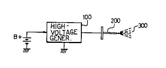
FIG. 1 is a conceptual view indicating a
general apparatus for generating anions;
FIG. 2 is a perspective view showing a
computer monitor adopting an apparatus for generating
anions according to the present invention;
FIci. 3 is an exploded view of the apparatus
depicted in 1.~'IG. 2; and
FIG. 4 is a longitudinal sectional view of an
apparatus of the present invention.
DETAILED DESCRIPTION OF THE PREFERRED EMBODIMENT
Typically, as to generation of anions, as
shown in FIG.. 1, a high-voltage generator 100 provides a
source of hi<~h DC 'voltage (B+), and applies the high
voltage to a discharge needle 200 to perform a corona
discharge. As the corona discharge ionizes the
surrounding <~ir, anions 300 are created, and emanate
from a main body o:f a product.

CA 02145247 2000-03-22
- 3a -
An apparatus for generating anions in video
appliances, the present invention, adapted to a computer
monitor is indicated i.n FIG. 2.
In FIG. 2, a supporting section 5 is inwardly
prepared on a housing 4 of a main body. An apparatus for
generating anions 6 is assembled in the supporting section
5.
l0 A detailed structure is shown in FIG. 3.
Two hemispheric projections 7 and two shafts 8 are
prepared on both sides of the apparatus for

2145247
-4-
generating anions 6 to fix the apparatus 6 to the
supporting section 5. It is often desirable that the
central parts of the shafts 8 are axially D-cut for easy
insertion.
Two recesses 9 in which the projections 7 are
latched and two bearings 10 in which the shafts 8 are
held, are provided on both inner sides 5A of the
supporting section 5.
Two elastic hooks 11 are formed projectingly
from the back of the apparatus for generating anions 6
to prevent the apparatus 6 from departing from the
supporting section 5.
At the back wall 5B of the supporting section
5, joining grooves 12 are prepared, in which the hooks
11 are joined.
By combining the hooks 11 with the grooves 12
and the shafts 8 with the bearings 10, the apparatus for
generating anions 6 is safely mounted in the supporting
section 5, which the apparatus 6 is pivotally movable
centering around the shafts 8. The hooks il play a part
in preventing the apparatus for generating anions 6 from
being detached from the supporting section 5 when the
apparatus 6 moves.
The hemispheric projections 7 are inserted
into the recesses 9 to fix the apparatus for generating
anions 6 at its regular position. Thereby the apparatus
6 cannot itself be opened.
If a user pulls out the apparatus 6 in order
to detach the projections 7 from the recesses 9, the
apparatus 6 is drawn out from the housing as shown in
FIG. 2.
In the apparatus for generating anions 6, as
shown in FIG. 4, there are several elements including an
air chamber 13 for inducing an air stream, an anion
chamber 14 in which anions are created by a corona

2145247
discharge, and a high-voltage chamber 15 for generating
a high voltage.
The upper part of air chamber 13 serves as an
exit 13B; its lower part as an entrance 13A. A side
wall 16 is formed as a funnel.
A high-voltage discharge needle 2 and a high-
voltage generator 1 are equipped in the anion chamber 14
and in the high-voltage chamber 15, respectively.
A ventilation hole 18 is perforated through a
l0 wall between the air chamber 13 and the anion chamber
14. An anticharge agent 19 is coated on the inner
surface of the anion chamber 14 to prevent electro-
deposition of anions. A power supply wire 20 is
connected to the high-voltage generator 1.
The operation of such a constructed apparatus
will be described.
When applying the power source, if a user
pulls out the apparatus for generating anions 6 from the
supporting section 5, the apparatus 6 is aslant drawn
2o from the supporting section 5 to the outside.
From the power source, the high-voltage
generator 1 generates a high voltage and applies the
high voltage to the discharge needle 2. Thereafter a
corona discharge between the discharge needle 2 and the
air ionizes the surrounding air to create anions. The
created anions are released to a room through the exit
14A.
An ascending air stream is formed in a main
body by convection caused by heat radiated from heating
elements in the main body. This air stream is led to
the air chamber 13 and exits towards the air.
The ascending air stream, entering the
entrance 13A and exiting the exit 13B of the air chamber
13, increases the release efficiency of anions released
from the anion chamber 14. Especially, the ascending

2145247
-6-
air stream, led to the anion chamber 14 through the
ventilation hole 18, lets the anions emanate more
vigorously.
What is more, because the side wall 16 of the
air chamber 13 is funnel-shaped (see FIG. 3) which
induces a Bernoulli effect of the ascending air stream,
the velocity of the air at the exit 13B becomes faster
so that the air emanating from exit 14A of the anion
chamber 14 are drawn (see FIG. 4) towards the exit 13A
of the air chamber 13. Thereby the anions are released
more quickly and forcefully from the anion chamber 14 to
an exterior room.
The anticharge agent 19 prevents the anions
from electrodepositing on the inner surface of the anion
chamber 14.
As a result, this invention releases anions
out of a main body using convention occurring due to
heat from heating elements inside the body, even without
a fan and fan driver.
To compensate for reduction of the amount of
released anions due to elimination of a fan, the
apparatus according to the present invention has been
designed to be able to be exposed to the peripheral airs
when used, which maximizes the amount of released
anions .

Representative Drawing
A single figure which represents the drawing illustrating the invention.
Administrative Status

2024-08-01:As part of the Next Generation Patents (NGP) transition, the Canadian Patents Database (CPD) now contains a more detailed Event History, which replicates the Event Log of our new back-office solution.

Please note that "Inactive:" events refers to events no longer in use in our new back-office solution.

For a clearer understanding of the status of the application/patent presented on this page, the site Disclaimer , as well as the definitions for Patent , Event History , Maintenance Fee  and Payment History  should be consulted.

Event History

Description Date
Inactive: Adhoc Request Documented 2018-06-06
Revocation of Agent Requirements Determined Compliant 2018-05-18
Appointment of Agent Requirements Determined Compliant 2018-05-18
Time Limit for Reversal Expired 2011-03-22
Letter Sent 2010-03-22
Inactive: Cover page published 2001-04-11
Grant by Issuance 2001-03-13
Inactive: Cover page published 2001-03-12
Pre-grant 2000-12-06
Inactive: Final fee received 2000-12-06
Letter Sent 2000-06-07
Notice of Allowance is Issued 2000-06-07
Inactive: Approved for allowance (AFA) 2000-05-02
Amendment Received - Voluntary Amendment 2000-03-22
Inactive: S.30(2) Rules - Examiner requisition 1999-11-24
Letter Sent 1999-01-21
Inactive: Status info is complete as of Log entry date 1997-12-04
Inactive: Application prosecuted on TS as of Log entry date 1997-12-04
Application Published (Open to Public Inspection) 1995-09-25
Request for Examination Requirements Determined Compliant 1995-03-22
All Requirements for Examination Determined Compliant 1995-03-22

Abandonment History

There is no abandonment history.

Maintenance Fee

The last payment was received on 1998-12-31

Note : If the full payment has not been received on or before the date indicated, a further fee may be required which may be one of the following

  • the reinstatement fee;
  • the late payment fee; or
  • additional fee to reverse deemed expiry.

Patent fees are adjusted on the 1st of January every year. The amounts above are the current amounts if received by December 31 of the current year.
Please refer to the CIPO Patent Fees web page to see all current fee amounts.

Owners on Record

Note: Records showing the ownership history in alphabetical order.

Current Owners on Record
LG ELECTRONICS INC.
Past Owners on Record
SEOK HWA JEONG
Past Owners that do not appear in the "Owners on Record" listing will appear in other documentation within the application.
Documents

To view selected files, please enter reCAPTCHA code :


To view images, click a link in the Document Description column. To download the documents, select one or more checkboxes in the first column and then click the "Download Selected in PDF format (Zip Archive)" or the "Download Selected as Single PDF" button.

List of published and non-published patent-specific documents on the CPD .

If you have any difficulty accessing content, you can call the Client Service Centre at 1-866-997-1936 or send them an e-mail at CIPO Client Service Centre.


Document
Description 
Date
(yyyy-mm-dd) 
Number of pages   Size of Image (KB) 
Description 2000-03-21 7 257
Claims 2000-03-21 3 88
Abstract 1995-09-24 1 11
Description 1995-09-24 6 233
Drawings 1995-09-24 3 42
Claims 1995-09-24 2 66
Representative drawing 1998-08-11 1 3
Representative drawing 2001-03-13 1 4
Commissioner's Notice - Application Found Allowable 2000-06-06 1 162
Maintenance Fee Notice 2010-05-02 1 170
Correspondence 1995-05-03 15 525
Correspondence 2000-12-05 1 31
Fees 1998-12-30 1 43
Fees 1998-12-22 1 48
Fees 2000-03-08 1 38
Fees 2001-03-14 1 37
Correspondence 1999-01-20 2 36
Fees 1998-03-18 1 43
Fees 1997-02-23 1 30