Note: Descriptions are shown in the official language in which they were submitted.
DIRECT SUPPORT FROG
BACKGROUND OF THE INVENTION
A railroad frog is a device which is inserted at the
intersection of a mainline rail and a turnout line rail to permit
the flanges of wheels moving along one of the rails to pass
across the other. The frog supports the wheels over the missing
tread surface between the frog throat and tY.e frog point and
provides flangeways for aligning the wheels when passing over the
point so that they will be afforded the maximum load bearing
area. Generally, standard turnout frogs may be classified as
rigid frogs which have no movable parts or movable wing frogs in
which one or both of the wings move outward to provide flangeways
for railroad car wheels. Rigid frogs include manganese railbound
frogs, solid manganese frogs and self guarded frogs. Movable
frogs include railbound manganese spring frogs.
Rigid railbound manganese frogs are constructed by combining
carbon steel rails with manganese steel castings. These frogs
are preferred over frogs which do not encompass manganese
castings inasmuch as manganese steel has a resistance to abrasion
and impact which exceeds that of carbon steel by as much as ten
times.
2~.~5~2~
- 2 -
In a conventional American Railroad Engineering Association
(A.R.E.A.) standard railbound frog installation, a frog casting
which may be manganese is clamped between a pair of wing rails.
Laterally extending fit pads are formed on opposite sides of the
frog casting to assist in positioning the casting with respect to
the wing rails which support the casting. The fit pads are
machined to complement the contour of the wing rail head and base
fishing surfaces and the rail web which extends therebetween.
Commonly, laterally extending bolts project through bores in the
wing rails and the frog casting to secure the wing rails to the
casting. This serves to locate the wing rails and the frog
casting such that the required gauge lines are maintained. The
bolted assembly further helps prevent longitudinal movement of
the rails due to thermal expansion and contraction.
Manganese steel has a resisi:ance to abrasion and impact
which greatly exceeds that of carbon steel. In part, this is
because of the metal's inherent ability to work harden. Although
manganese steel's extreme resistance to abrasion makes it
preferred for heavy rail traffic usage such as in frog areas,
this same characteristic makes the metal extremely difficult to
machine. The material does not conform to traditional guidelines
for machining steel. Instead, manganese steel requires very low
rates of feed and slow cutter speeds. Machine tool cutters must
be configured to allow for very heavy cuts with high chip loads
inasmuch as all material must be removed from each surface in a
single tool pass due to the work hardening characteristics of the
metal. Cutter tool life is short even where the inserts are
formed from special grades of carbide and ceramic materials. The
- 3 -
conventional A.R.E.A. railbound manganese frog casting requires
extensive machining of relatively complex shapes. The fit pads
must be shaped to complement the webs and fishing surfaces of
wing rails as stated above. Additionally, in a traditional frog
the frog casting rests upon the angled fishing surface of the
wing rail bases along the entire length of the interface between
the casting and the wing rails this being the full length of the
casting. This is illustrated in Fig. 3 of the drawings.
Consequently, the entire bottom surface of the casting must be
machined on both sides. This is time consuming and expensive.
Because the frog casting rests upon the fishing surfaces of
the wing rail bases, loads borne by the tread surface of the
casting are transmitted downwardly through the vertical side
walls of the casting directly into the angular rail bases. This
results in a grating action between the casting and the rail base
mating surfaces due to the cyclic loading imposed therein by each
passing rail car wheel. The grating action causes the surfaces
to abrade which ultimately loosens the fit between the surfaces.
Additionally, a portion of the vertical loads imposed upon the
tread surface and side walls of the casting result in a lateral
component of force being imposed upon the wing rail bases. This
of course results because the load is not imposed at right angles
to the base. The lateral force tends to bias the wing rails
laterally outwardly from the casting. This loading tends to
loosen the interface between the wing rails and the casting and
imparts a tensile load to the bolts which clamp the casting
between the wing rails. The cyclical tensile loading can result
2~4~~~~
- 4 -
in failure of bolt assemblies and ultimate failure of the frog
assembly.
Despite the inherent strength of manganese steel, higher
train speeds and greater wheel loading which have become more
prevalent in recent times have caused manganese frogs to exhibit
evidence of failure after prolonged usage. Such failure has
included crushed or collapsed tread areas believed to be
symptomatic of shrinkage voids in the casting and spreading of
the gauge lines both due to heavy wheel loads.
One type of frog casting which addressed these problems
resulted in a railbound manganese frog having a "boxed-in" design
commonly referred to as an "integral base" configuration. This
structure has a bottom surface which sometimes is co-planar with
the base surface of the wing rails and also has a continuous
interface between the lower portion of the casting side wall and
the upper angled or fishing surface of a wing rail flange. This
interface extends the entire length of a casting. This design
structure utilizes a longitudinally extending center wall or rib
which extends between the underside of the upper running surface
and the horizontal bottom wall. A significant degree of success
was achieved with this design in terms of preventing crushing of
the casting tread areas.
However, difficulties were encountered in the manufacture of
the frog casting. It was found that the extensive use of sand
cores in the drag portion of the mold which cores were required
to produce the internal cavities resulted in chronic porosity of
the casting. This porosity resulted from gases emanating from
the breakdown of ~he organic binding agents utilized to harden
the sand cores. Additionally, because of the large number of
cores used in making the casting, problems frequently were
encountered with non uniform cross-sectional thicknesses due to
shifting of the cores in the drag portion of the mold.
While an integral base casting having a central
longitudinally extending rib has substantially increajed the life
over that of a conventional manganese frog casting, it was
desirable to develop a railbound manganese frog which would
achieve greater casting life while reducing the complexity of the
casting both in terms of internal passages and in terms of the
amoant of machining required to enable the casting to be fit to
the wing rails.
The instant invention achieves this objective with a direct
support railbound manganese frog having a frog casting which is
clamped between mainline and turnout line wing rails but is
freestanding such that substantially the entire bottom surface of
the casting is spaced from the base of the wing rails and rests
upon rail plates or other rail support structure. Consequently,
the loads imposed on the casting by rail car wheels passing over
20the tread surfaces thereof are transferred directly into the
frog supporting structure such as rail plates thus bypassing the
wing rails themselves. This is accomplished by positioning the
vertical side walls of the frog casting immediately below the
load bearing surfaces and extending the walls downwardly to the
base plate. To accomplish this, the inner base flange of each
wing rail is cut away t~ provide clearance for the adjacent
casting side wall. With this direct support frog design,
CA 02145428 2000-02-10
- 6 -
abrasion between the frog casting and the wing rails is eliminated
and no lateral loads are transmitted through the rail to the bolts
which clamp the wing rails and frog casting together to form a
railbound manganese bound assembly.
SUGARY OF THE INVENTION
A frog assembly is mounted on a base plate and has a
fixed wing longitudinally extending railroad frog casting securely
clamped between a pair of wing rails at the intersection of a
mainline rail and a turnout line rail. The casting has a planar,
longitudinally extending bottom support surface, a heel end, a heel
extension adapted to be clamped between a pair of heel rails and
a frog point integral with the heel. The frog point is defined in
part by the bottom surface, a pair of diverging side surfaces and
a top surface which defines a mainline running surface and a
turnout line running surface for railroad car wheels. The casting
also includes a toe end having a first wing and a second wing each
defined in part by the bottom surface, an outer longitudinally
extending perimeter side wall and a top wheel running surface . The
first and second wings of the casting lie on opposite sides of and
extend forwardly of the frog point and extend parallel to and are
spaced laterally from one of the diverging side surfaces of the
point to define a flangeway groove therebetween. A first wing rail
has a base with a bottom surface which rests on the base plate and
a pair of opposed inclined fishing surfaces connecting by a web to
a head having a mainline wheel running top surface and a pair of
opposed inclined fishing surfaces. A second wing rail has a base
with a bottom surface which rests on the base plate and a pair of
opposed inclined fishing surfaces connected by a web to a head
CA 02145428 2000-02-10
having a turnout line wheel running top surface and a pair of
opposed inclined fishing surfaces. The first wing rail has a first
wing receiving section which complements and extends parallel to
the perimeter side wall of the first wing and receives the first
wing and a first guard rail section mounted on the base plate . The
second wing rail has a second wing receiving section which
complements and extends parallel to the perimeter side wall of the
second wing and receives the second wing and a second guard rail
section mounted on the base plate. The top wheel running surfaces
of the first and second wings are parallel to the mainline and the
turnout line wheel running surfaces of the wing rails and the
bottoms of the first and second wings are parallel to the bottom
surface of the first and second wing rails. The railroad frog
casting is freestanding such that substantially the entire bottom
surface of the casting is spaced from the base of each of the wing
rails. Aligned holes are formed in the first and second wing rails
and the railroad frog casting. Bolts are inserted into the aligned
bores to clamp the frog casting between the first and second wing
rails.
DESCRIPTION OF THE DRAWINGS
Fig. 1 is a plan view of the rigid railbound frog of the
instant invention;
Fig. 2 is a plan view of the frog casting of the instant
invention;
Fig. 3 is a cross-sectional view of a prior art railbound
frog assembly showing a frog casting supported on the bases of a
pair of wing rails;
~145~~$
Fig. 4 is a view along line 4-4 of Fig. 2 at the toe of the
casting;
Fig. 5 is a view along line 5-5 of Fig. 2 at the toe of the
casting;
Fig. 6 is a vi ew along line 6-6 of Fig. t at the throat of
the casting;
Fig. 7 i~ a view along line 7-7 of Fig. 2 at the point of
the casting;
Fig. 8 is a view along line 8-8 of Fig. 2 through the point
of the casting;
Fig. 9 is a view along line 9-9 of Fig. 2 through the point
of the casting;
Fig. 10 is a view along line 10-10 of Fig. 2 at the heel of
the casting; and
Fig. 11 is a view along line 11-11 of Fig. 2 at the heel of
the casting.
DESCRIPTION OF THE PREFERRED EMBODIMENT
The direct support railbound frog of the present invention
incorporates a frog casting having a bottom surface spaced from
the wing rails and adapted to rest directly on a rail plate.
With this configuration wheel loads on the top surface of the
casting are transferred directly into the supporting structure
for the frog without passing through the wing rails. As a
result, cyclic forces caused by wheel leads imposed on the
casting are not transferred to flanges of wing rails and lateral
forces are not imposed upon the bolts affixing the wing rails to
~I~~4
- 9 -
the frog casting. Additionally, the vertical side walls of the
frog casting are positioned immediately below the load bearing
surfaces of the casting to provide better support for the cyclic
loads imposed on the casting. This increases the strength of the
casting and enables the casting structure to be simplified.
Furthermore, because the frog casting is not supported on the
wing rails, it does not have to be contoured to complement the
rails and expensive machined surfaces on the fit pads and on the
top and bottom of the casting are avoided.
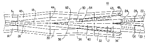
Turning to the drawings, Fig. 1 depicts a direct support
railbound manganese frog (10) of the present invention.
Ordinarily, frogs are classified either as left-hand or as right-
hand. The frog is considered left-hand when the turnout gauge
line is on the left-hand side of the point and the mainline gauge
line is on the right-hand side of the pint as the point is
viewed looking from the toe end toward the heel end of the frog.
A frog would be considered right-hand if the turnout gauge line
is on the right-hand side of the point and the mainline gauge
line is on the left-hand side of the point as viewed from the toe
end looking towards the heel end of the frog. The railbound frog
(10) of the present invention will fit a left-hand or a right-
hand frog application because it is symmetrical about a
longitudinal centerline. However, for purposes of this
description, frog (10) will be considered a right-hand frog.
Frog (10) has three main components. These components are a
central longitudinally extending frog casting (12) which is
bounded on opposite sides and clamped between a right-hand wing
~I~~
- 1~ -
rail (14) and a left-hand wing rail (16). Preferably, frog
casting (12) is constructed of manganese steel because of its
strength and work hardening characteristics. However, the direct
support features of the instant invention are not limited to a
railbound frog in which the frog casting is manganese. The
right-hand and left-hand wing rails (14 and 16) connect to
mainline and turnout traffic rails, not shown, at the toe end
(18) of frog (10). Right-hand and left-hand heel rails (20 and
22) are attached to the heel end (24) of frog (10). In the
construction depicted in Fig. 1, right-hand and left-hand heel
rails (20 and 22) are attached to frog casting (12) by flash butt
welds (26 and 28). Alternatively, heel rails (20 and 22) may bE
affixed to the heel end (24) of casting (12) by bolt assemblies.
Right-hand wing rail (14) has a mainline running surface
(28) designed to support the tread of a rail car wheel, not
shown, a right-hand wing receiving section (30) which receives a
wing of casting (12) which will be described in detail
hereinbelow and a right-hand guard rail section (32) which
terminates with a flared end (34). By making end (34) flared, a
railroad car wheel traversing frog (10) in a trailing movement
direction, i.e. from the heel end (24) toward the toe end (18)
cannot strike the outer end of guard rail section (32). Guard
rail section (32) functions to guard a railroad car wheel
traveling in a flangeway (36) defined between a side surface (38)
formed on one side of the frog point of frog casting (12) and
guard rail section (32). The side surface (38) defines the gauge
line for a wheel moving across a turnout line running surface
w I~542
- 11 -
(40) defined on frog casting (12) and described in greater detail
hereinbelow.
Left-hand wing rail (16) has a turnout wheel running surface
(42) which supports the tread of a wheel moving along the turnout
rail, a wing receiving section (44) adapted to receive a wing of
frog casting (12) and a guard rail section (46). Guard rail
section (46) terminates with a flared end (48) and functions to
guide a wheel which traverses a flangewal~ (50) defined between a
side surface (52) formed on one side of the frog point of frog
casting (12) and guard rail section (46). Side surface (52)
defines the mainline gauge line for a wheel moving across a
mainline running surface (54) on frog casting (12).
Details of frog casting (12) may be seen by referring to
Fig. 2. Figs. 4 through 11 illustrate various cross-sectional
portions of casting (12) depicted in Fig. 2 combined with right-
hand and left-hand wing rails (14 and 16). Frog casting (12) has
a bottom surface (56) adapted to rest directly upon a rail plate
(58) or other rail support surface as depicted in Fig. 4.
Casting (12) has a heel extension (60) which projects from the
heel end (24) thereof and attaches to a pair of heel rails (20
and 22) as described hereinbefore. Casting (12) incorporates a
frog point (62) integral with said heel end (24) defined in part
by said bottom surface (56), the diverging side surfaces (38 and
52) and a top surface (64) which defines turnout running surface
(40) and mainline running surface (54). Surface (64) terminates
at the frog point (62) at the toe end (18) of casting (12).
The tip (66) of frog point (62) is positioned between right-
hand and left-hand wing (68 and 70) near frog throat (72). The
CA 02145428 2000-02-10
- 12 -
wing (68 and 70) provide transition surfaces for railroad car
wheels moving between the turnout and mainline running surfaces (40
and 54) formed on the top surface (64) of frog point (62) and the
mainline and turnout wing running surfaces (28 and 42).
Right -hand wing ( 6 8 ) i s spaced f rom the s ide surf ace ( 3 8 )
of frog point (62) by flangeway groove (36) and is defined in part
by the bottom surface (56) of frog casting (12), an outer
longitudinally extending perimeter side wall (76) and the top wheel
running surface (28) . A portion of left-hand wing (70) extends
parallel to the side surface (52) of frog point (62) and is spaced
laterally from the surface by flangeway groove (50). Left-hand
wing (70) is defined in part by the bottom surface (56) of frog
casting (12), an outer longitudinally extending perimeter side wall
(82) and the top wheel running surface (42).
Referring again to Fig. 2 it may be observed that a
plurality of laterally extending positioning pads (84) are attached
to the outer longitudinally extending perimeter side walls (76 and
82) of right-hand and left-hand wings (68 and 70) respectfully at
the toe end (18) of frog casting (12). Positioning pads (86) also
project laterally from the side walls (88 and 90) at the heel end
(24) of frog casting (12). Positioning pads (84 and 86) laterally
position frog casting (12) with respect to right-hand and left-hand
wing rails (14 and 16) when the rails are joined to the casting to
form the direct support railbound frog (10) of the instant
invention. Preferably, the perimeter side walls (76 and 82) of the
right-hand and left-hand wings (68 and 70) and the vertical side
walls (88 and 90) of the heel end (24) have a substantially uniform
thickness and shape from one end of the frog casting (12) to the
CA 02145428 2000-02-10
- 12a -
other to aid uniform solidification of the frog casting (12).
Turning to Fig. 4, it may be observed that at least one
lateral bore (92) is formed in frog casting (12) in the area of
~~.~~4~~
- 13 -
each positioning pads (84 and 86) . In other words, the lateral
bores (92) pass through the positioning pads (84 and 86). Each
of the bores (92) is aligned with similar bores (94 and g6)
formed in the adjacent wing rails (14 and 16). Bolts, not shown,
are inserted into the aligned bores (92 - ~6) to clamp frog
casting (12) between wing rails (14 and 16) to form the direct
support railbound frog (10).
Right-hand wing rail (14) has a base (98) and a head (100)
which are joined by a vertical web (102). Base (98) has a pair
of opposed angled top or fishing surfaces (104 and 106) which
project from opposite sides of web (102). A pair of opposed
angled fishing surfaces (108 and 110) also are formed on the
bottom of rail head (100). Similarly, left-hand wing rail (16)
has a base (118) joined to a head (120) by a vertical web (122).
Base ( 118 ) has a pair of angled or top or fishing surfaces ( 124
and 126) and head (120) has a pair of lower angled fishing
surfaces (128 and 130). Referring again to Fig. 4, it may be
observed that each of the positioning pads (84) has a pair of top
angled surfaces (132) and a bottom angled surfaces (134) which
complement the fishing surfaces (108 and 128) formed on the heads
(100 and 120) of wing rails (14 and 16) and the fishing surfaces
(104 and 124) formed on the bases (98 and 118) of these rails.
It should be noted that the angled surfaces (132 and 134) of
the positioning pads (84) serve only to laterally position frog
casting (12) with respect to the wing rails (14 and 16). It also
should be noted that the outer side walls (136) of the
positioning pads (84 and 86) are spaced from the webs (102 and
122) of the wing rails (14 and 16). It is not necessary that the
CA 02145428 2000-02-10
- 14 -
outer side walls (136) be shaped to complement and engage these
webs because the positioning pads are not serving to support the
frog casting (12) on the rails (14 and 16) as has been done in the
past. The casting is supported by having base (56) engage the top
surface of rail plate (58). Thus, the weight of the frog casting
(12) and the railroad car wheel loads imposed on the casting are
transmitted directly to the rail plate (58) without passing through
the wing rails (14 and 16).
Referring again to Fig. 4, it may be seen that the side
walls (76 and 82) of the frog casting (12) are aligned with the top
running surfaces (28 and 42). The side walls (76 and 82) extend
substantially vertically downwardly and intersect the bottom
surface (56) of frog casting (12). In other words the side walls
(76 and 82) are substantially aligned with the wheel running
surfaces (28 and 42). This is made possible because the bases (98
and 118) of the right and left-hand wing rails are cut adjacent the
bottom support surface (56) of the frog casting (12). It may be
seen that the base of wing rail (14) is cut to form a side wall
(138) which is substantially aligned with the inner vertical side
wall (139) of the head (100) of that rail. Similarly, the base
(118) of left-hand wing rail (16) is cut such that a side wall
(140) is substantially aligned with the inner vertical side wall
(142) of the head (120) of that rail. Although the direct support
frog (10) of this invention requires that the bases of the wing
rails (14 and 16) be cut to accommodate the expanded base surface
(56), machining of the frog casting (12) is substantially reduced
with this design.
~14~4~~
- ~~ -
Turning to Fig. 3, a prior art railbound manganese frog may
be seen in contrast to the direct support frog of this invention.
It should be noted that in the prior art frog, a pair of wing
rails wrap around the body of the frog casting. Fit pads extend
from opposite sides of the casting and are machined to complement
the fishing surfaces formed on the bases and heads of the wing
rails as well as the webs of these rails. With this
configuration, the frog casting is supported upon the fishing
surfaces of the rail bases along the entire length of the
casting. Loads borne by the tread surfaces of the casting are
transmitted downwardly through the vertical side walls of the
casting into the rail bases. Because the rail flanges support
the frog casting, the cyclical loading caused by successive rail
car wheels causes a grating action between the mating surfaces of
the bottom of the frog casting and the fishing surfaces on the
wing rail bases. This action causes both surfaces to abrade
which ultimately results in the frog assembly becoming loose.
Additionally, a portion of the vertical load on the frog casting
imposed on the fishing surfaces of the rail bases results in
opposed lateral forces acting to bias the wing rails apart.
These forces impose a tensile loading on the bolts which clamp
the rails to the frog casting. The cyclical tensile loading may
result in failure of the bolt assembly which as a minimum forces
replacement of the bolt assembly and may cause failure of the
entire frog assembly. Grating action between the base of the
frog casting and the wing rail fishing surfaces and the
imposition of tensile forces on the bolts clamping the rails to
the casting are avoided in Applicant's direct support railbound
21~~4~~
- 16 -
frog. The reason for this resides in the fact that in
Applicant's frog the frog casting is not supported by the wing
rails. Instead, in Applicant's frog the frog casting is
supported on a rail plate or any other rail support surface.
This is evidenced by the fact that the base of Applicant's frog
casting is spaced from the bases of the wing rails.
Figs. 5, 6 and 9 are cross-sectional views through the toe
end (18) of Applicant's frog casting. Each of these sections
show the positioning pads (84) cooperating with the adjacent wing
rails (14 and 16). In each of these views it may be seen that
the base (56) of the frog casting (12) is spaced from the bases
(98 and 118) of the wing rails (14 and 16) such that it rests
directly on the rail plate (58). Additionally, the positioning
pads (84) engage only the fishing surfaces formed on the rails
(14 and 16). Also, it should be noted that the vertical side
walls (76 and 82) of the frog casting (12) are positioned
immediately below the load bearing surfaces of the< casting and
extend directly to the rail plate.
Figs. 7 and 8 are cross-sectional views of the toe end (18)
of the frog casting (12) through sections which do not have
positioning pads (84). Again, these views show the casting (12)
touching only a single point or surface on the heads of the wing
rails (14 and 16) and the botto~; surface (56) spaced from the
wing rail bases (98 and 118). Clearly, frog casting (12) is not
supported in any manner by the wing rails (14 and 16). Views (10
and 11) are of the heel end (24) of the frog casting (12). At
the heel end (24) of the casting the positioning pads are
2144
_ i, _
identified by the numeral (86). The elements of these pads
identical to the elements of the position pads (84) at the toe
end (18) of the casting are identified by identical primed
numbers. These views also show the bottom surface of frog
casting (56) spaced from the bases (98 and 118) of wing rails (14
and 16). Additionally, Fig. 11 shows the outer side wall (136')
of. the positioning pad (86) spaced from the webs (102 and 122) of
these rails.
Turning again to Figs. 4 through 11 it may be observed that
there are no horizontal bottom walls forming internal passages in
frog casting (12). No horizontal bottom walls are required in
this casting because the side walls (76 and 82) of the casting
are substantially aligned with the running surfaces (28 and 42)
thereof. This construction provides adequate strength to the
casting without having to resort to the added complexity of a
horizontal bottom wall and internal cavities. As a result, all
internal cores and the gas porosity problems associated with such
cores are eliminated. It may be observed that the side wall
thicknesses of the casting (12) are constant and have minimal
surface contour. This results in improved castability. The frog
(10) of this invention requires minimal machining which is of
particular importance when working on a casting made of manganese
steel. All machined surfaces are flat; either parallel to the
machine table or flat at an angle. No compound flat or contoured
surfaces are utilized. This substantially reduces the amount of
machining required for the casting.
Since certain changes may be made in the above-described
system and apparatus without departing from the scope of the
~~4~4~8
- 18 -
invention herein and above, it is intended that all matter
contained in the description or shown in the accompanying
drawings shall be interpreted as illustrative and not in a
limiting sense.