Language selection

Search

Patent 2145459 Summary

Third-party information liability

Some of the information on this Web page has been provided by external sources. The Government of Canada is not responsible for the accuracy, reliability or currency of the information supplied by external sources. Users wishing to rely upon this information should consult directly with the source of the information. Content provided by external sources is not subject to official languages, privacy and accessibility requirements.

Claims and Abstract availability

Any discrepancies in the text and image of the Claims and Abstract are due to differing posting times. Text of the Claims and Abstract are posted:

  • At the time the application is open to public inspection;
  • At the time of issue of the patent (grant).
(12) Patent: (11) CA 2145459
(54) English Title: HIGH SPEED LAYING HEAD
(54) French Title: TETE DE LAMINOIR ULTRARAPIDE
Status: Term Expired - Post Grant Beyond Limit
Bibliographic Data
(51) International Patent Classification (IPC):
  • B21B 39/14 (2006.01)
  • B21C 47/14 (2006.01)
(72) Inventors :
  • SHORE, TERENCE M. (United States of America)
  • WOODROW, HAROLD E. (United States of America)
(73) Owners :
  • SIEMENS INDUSTRY, INC.
(71) Applicants :
  • SIEMENS INDUSTRY, INC. (United States of America)
(74) Agent: SMART & BIGGAR LP
(74) Associate agent:
(45) Issued: 1999-01-12
(22) Filed Date: 1995-03-24
(41) Open to Public Inspection: 1995-10-27
Examination requested: 1995-03-24
Availability of licence: N/A
Dedicated to the Public: N/A
(25) Language of filing: English

Patent Cooperation Treaty (PCT): No

(30) Application Priority Data:
Application No. Country/Territory Date
08/233,315 (United States of America) 1994-04-26

Abstracts

English Abstract


A rolling mill laying head as a quill supported for rotation about its longitudinal axis
between axially spaced first and second bearing assemblies. A laying pipe is carried by the quill
for rotation therewith. The laying pipe has an entry section lying on the quill axis between the
first and second bearing assemblies, and a three dimensionally curved intermediate section
extending through and beyond the second bearing assembly to terminate at a delivery end spaced
radially from the quill axis to define a circular path of travel. The dimension by which the
laying pipe extends beyond the second bearing assembly is less than the diameter of the circular
path.


French Abstract

Tête de laminoir à fourreau supportée, aux fins de rotation, sur son axe longitudinal entre un premier et un deuxième roulements séparés axialement. Un conduit est porté par le fourreau pour en assurer la rotation. Le conduit présente une section d'entrée réalisée sur l'axe du fourreau, entre les premier et deuxième roulements, et une section intermédiaire tridimensionnelle courbée passant dans le deuxième roulement et en ressortant, pour se terminer à une extrémité de sortie espacée radialement de l'axe du fourreau de manière à constituer une voie d'acheminement circulaire. La dimension du conduit sortant du deuxième roulement est inférieure au diamètre de la voie circulaire.

Claims

Note: Claims are shown in the official language in which they were submitted.

THE EMBODIMENTS OF THE INVENTION IN WHICH AN EXCLUSIVE
PROPERTY OR PRIVILEGE IS CLAIMED ARE DEFINED AS FOLLOWS.
1. In a rolling mill, a laying head for receiving a single strand product moving axially
at a speed of at least 120 m/sec and for forming said product into a continuous series of
rings, said laying head comprising:
a quill having a longitudinal axis;
first and second bearing assemblies encircling and supporting said quill for rotation
about
said axis, the centers of said first and second bearing assemblies being located
respectively in first and second mutually spaced reference planes perpendicular to said axis;
means for rotating said quill about said axis; and
a laying pipe carried by said quill for rotation therewith about said axis, said laying
pipe having an entry section lying on said axis between said first and second bearing
assemblies and into which said product is directed, and having a three dimensionally curved
intermediate section leading from said entry section across said second reference plane to
terminate at a delivery end from which said product emerges to form said continuous series
of rings, said delivery end being spaced radially from said axis to define a circular path of
travel for said delivery end around said axis and being spaced from said second plane by an
overhang distance which is less that the diameter of said circular path of travel.
2. The laying head of claim 1 wherein said overhang distance is between 0.77 and 0.83
of the diameter of said circular path of travel.
-7-

3. The laying head of claim 1 wherein said second bearing assembly has a D m N number
above 1,000,000.
4. The laying head of claim 1 wherein the distance between said first and secondreference planes is greater than said overhang distance.
-8-

Description

Note: Descriptions are shown in the official language in which they were submitted.


2145459
-
S~ 1013
BACK(~ROUND OF TIIE INVENT~ON
1. Field of the Invention
This invention relates generally to high speed rod rolling mills, and is concerned in
particular with improvements in the laying heads used to form the hot rolled products of such
mills into helical ring formations for deposit on cooling conveyors and the like.
2. Description of the Prior Art
A conventional laying head is depicted in Figure I at 10. The laying head has a housing
12 and a quill 14 supported between first and second bearing assemblies 16, 18 for rotation
about its axis "X". The centers of the bearings 16, 18 lie in respective reference planes Pl, P2
spaced one from the other by a distance "B". The second bearing assembly 18 has a bore
diameter "D".
Quill 14 carries a bevel gear 20 meshing with a larger diameter bevel gear 22, tne latter
being driven by conventional means (not shown). A laying pipe 24 is carried by the quill for
rotation therewith. The laying pipe has an entry section 24a Iying on the quill axis X between
the first and second bearing assemblies 16, 18, and a three dimensionally curved interme~ s~
section 24b leading from the entry section across reference plane P2 to a delivery end 24c. The
delivery end is spaced from reference plane P2 by an overhang ~ict~nce ~A", and is spaced
radially from axis X to define a circular path of travel having a di~meter "F". The laying pipe
is held by a pipe support structure 26 comprising arms extending radially from the quill. Hot
rolled product is directed into the entry section 24a of the laying pipe, and emerges from the
-1-

59 ~ g~gg7
delivery end ~4~ as a contil~uollc helical fo,l"~,lion of rings having di~met~rs F.
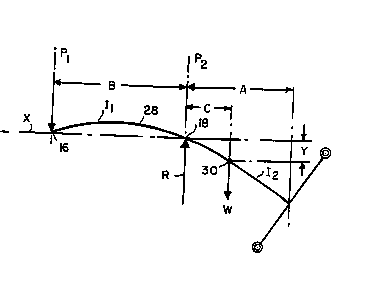
With reference to Figure _, it will be seen that under static con~litiQnc~ the rotating
assembly comprising the ~uill, laying pipe and support 5~1uC~ulc deflects under its own weight
~W" as in~ir~-P~ diagr~mm~ic~lly by the curve 28 (exaggerated for purposes of illustration).
Thus, the centroid 30 of the rotating assembly will depart }aterally from the axis of rotation ,~
by a d~ nre "Y". The exlent to which lateral centroid deflection Y is minimized is considered
to be a measure of the "stiffness" of the laying head.
It is generally accepted that a safe o~e.dling speed for a laying head is not more than
about 65% of the critical r~so~l~n~e speed of the rotating assembly. Critical resonance speed
~aries inversely as the square root of the lateral deflection Y.
Laying heads are currently operating c~ti~f~torily at mill delivery speeds on the order
of 100-110 m/sec. HoweYer, as these speeds con~inn~ to increase to 120 mlsec and higher, the
ability of conventional laying heads to function c~ f~rtorily at these elevated speeds is projected
to become increasingly probl~m~ic~h The reason appears to be inadequate stiffness. which not
only lowers the critical reson~nce speed of the rotating assembl~, but also leads ~o the
introduction of unacceptably pronounced vibrations.
SUMMARY OF THE INVENTION
In accordance with one aspect of the present invention there is provided in a rolling
mill, a laying head for leceivi.lg a single strand product moving axially at a speed of at least
120 m/sec and for forrning said product into a continuous series of rings, said laying head
-2- ;~

- ~ ~ 4 ~
comprising: a quill having a longih1(1in~1 axis; first and second bearing assemblies encircling
and supporting said quill for rotation about said axis, the centers of said first and second
bearing assemblies being located respectively in first and second mutually spaced reference
planes perpendicular to said axis; means for rotating said quill about said axis; and a laying
pipe carried by said quill for rotation therewith about said axis, said laying pipe having an
entry section lying on said axis between said first and second bearing assemblies and into
which said product is directed, and having a three dimensionally curved intermediate section
leading from said entry section across said second reference plane to termin~te at a delivery
end from which said product emerges to form said continuous series of rings, said delivery
end being spaced radially from said axis to define a circular path of travel for said delivery
end around said axis and being spaced from said second plane by an overhang distance which
is less that the diameter of said circular path of travel.
The present invention stems from the determination that a primary contributing factor
to inadequate laying head stiffness is the extent of overhang of the quill and laying pipe
beyond the second bearing assembly. In conventional laying heads, the extent of overhang
is invariably greater than both the diameter of the rings being formed by the laying head and
the axial spacing between the first and second bearing assemblies. In accordance with the
present invention, it is preferable that overhang is reduced to a fraction of these dimensions,
thereby resulting in a stiffer construction which can be balanced more reliably and operated
safely at higher speeds.
:~7~
~'
.~ .,

Hl~ ~ 9 ~9g1
BRTEFDESCR~ ON OFT~E DR~ NGS
Figure 1 ~ t~-~s the ~.,"ci~al co~ponc~tc of a conventicm~l rolling mill laying head;
Figure ' is force diagram depicting the deflec~ion of the rotating assembly of a laying
head under static con~;l;on~; and
Figure 3 is an il~ .,.l;.." of the ~ ;nf~ ;p of laying pipe o~C,i~lg to the bore
of the second bearing assembly.
pF.SCR~ ON OF PREFERRED E~BOD~MENT
In the past, the spectre of speed induced bearing failures has influ~nred those slcillc-d in
the ~trt to hold the so-called "DmN number" (Mean Diameter X RPM) of the second beartng
assanbly 18 to beiow about 1,000,000. Thus, as laying head RPM's haYe nr~ ci~ Ily inclcascd
to ~cep pace with eYer increasing mill delivery speeds, and in order to hold DmN ratings within
what was perceiYed to be safe limits, bearing bore diameters were l.d~ cd. Howe-~er, as
m~r-r D
-3a- ~,C~

M~Y - 9 ~
4 ~ ~
of the second bearing assembly 18.
The present invention departs from conventional thinking by increasing the DmN rating
of the second bearing assembly by as much as 50% to levels approaching 1,600,000. At these
elevated DmN levels, increases in both RP~'s and bearing bore rli~mpters can be tolerated. The
increased bore diameters ma};e it possible to axially retract the curved intermediate section '4b
of the laying pipe into the quill 14. Thus, as shown in Figure 3, an increase ~D in bore
diamcter from Dl to D2 will accommodate a decrease -~A in overhang from Al to A2. Any
decrease ~A in the overhang will result in a concomitant decrease in the ~icr~nce "C" that the
centroid 30 is spaced from the plane P2 of the second bearing assembly. Since deflection Y is
calculated as
Y = W C 2B/3 E Il + W C3/3 E I 2
where, 11 = mean moment of inertia of quill cross section
I2 = mean moment of inertia of pipe support cross section
E = modulus of elasticity
it will be seen Ihat by decreasing C, Y will also be de~,~sed, thereby increasing the stiffnPcc
and cri~ical resonance speed of the laying head.
In order to further reduce deflection Y for any given value of C, the spacing B between
the first and second bearings 16, 18 also should be as small as possible. However, and again
with reference to Figure ', it must be kept in mind that the load on bearing 18 is e~ual to the
reaction "R" which can be e:~pressed as
R = W (CIB + 1)
Thus, any decrease in B will increase the loading on beanng 18. This would normally
-4--
,:

- J~ 5 ~ Y ~9 19~7
not be a problem if the bearing were rated at conventional DmN numbers below about
1,000.00. However, at the elevated DmN ratings of the present invention, the number of
rolling el~m~lt~ must be reduced in order to ~col"."o~ e lu~-;c~ult ~n~dtion, thereby
reducing the useful life of the bearing for any given load.
In accordance with the present invention. the DmN rating of the second bearing assembly
is elevated such that for a given mill delivery speed, the p~lllitled increase in bore di~met~r D
will accommodate a decrease in overhang A to less than the ring diame~er F. Be3ring load is
kept within tolerable limits by insuring that the spacing B between the bearings 16, 18 remains
greater than the overhang A.
Table A is illustrative of what can be achieved at a mill delivery speed of 150 mlsec
when the bore diameter of the second bearing assembly is sized with a mean ~i~met~r of 550
mm, and the bearing is operated at elevated DmN numbers in accordance with the present
invention.
TABLE A
DELIVE~Y D B F A DmN A/F
SPEED
(m/sec) (mm) (mm) (mm) (mm)(Brg. 18)
1200 9911,313,028 0.83
1170 9581,346,695 0.82
1125 9081 400,564 0.80
150 550 ~ 154
1075 85~1,465,706 0.79
1035 8111,522,352 0.78
1000 7731,575,633 0.77
It will be seen from Table A that by elevating the DmN rating of the second bearing
C ~ sQu~

M~ g ~
assembly 18 ~o well above 1,000,000, a bore ~ e~ D of 500 mm can be employed at mill
delivery speeds of 150 m/sec to produce ring tii~m~ters ranging from 1,000 - 1,200 mm. In
all cases, the overhang A is concid~ably less than the rli~mP~er of the rings being formed, and
the dict~nce B between the b~-ings 16, 18 is greater than the overhang A.
These dimensions and DmN numbers will vary deperlriing on the delivery speed of the
mill and the size of the rings being formed by the laying head. However, central to the present
invention is the shortening of the overhang A to less than the ring di~meter F. As a result,
centroid deflection Y is minirrli7Pd, thereby raising the critical reson~nce speed of the laying
head, which in tum m~;es it possible to operate safely at higher speeds. Reduced o-erhang is
made possible by subs~nlially increasing the DmN rating of the second bearing assembly in
order to obtain the benefit of a larger bore ~i~meter~ Bearing load is maintained within tolerable
limits by insuring that the spacing between the be~ings 16, 18 is greater than any overhang
beyond the second bearing 18.
.~

Representative Drawing
A single figure which represents the drawing illustrating the invention.
Administrative Status

2024-08-01:As part of the Next Generation Patents (NGP) transition, the Canadian Patents Database (CPD) now contains a more detailed Event History, which replicates the Event Log of our new back-office solution.

Please note that "Inactive:" events refers to events no longer in use in our new back-office solution.

For a clearer understanding of the status of the application/patent presented on this page, the site Disclaimer , as well as the definitions for Patent , Event History , Maintenance Fee  and Payment History  should be consulted.

Event History

Description Date
Inactive: Expired (new Act pat) 2015-03-24
Letter Sent 2010-12-07
Inactive: Office letter 2010-05-18
Revocation of Agent Request 2010-03-09
Appointment of Agent Request 2010-03-09
Inactive: IPC from MCD 2006-03-11
Grant by Issuance 1999-01-12
Pre-grant 1998-08-27
Inactive: Final fee received 1998-08-27
Notice of Allowance is Issued 1998-03-10
Letter Sent 1998-03-10
Notice of Allowance is Issued 1998-03-10
Inactive: Status info is complete as of Log entry date 1998-03-05
Inactive: Application prosecuted on TS as of Log entry date 1998-03-05
Inactive: Approved for allowance (AFA) 1998-02-11
Application Published (Open to Public Inspection) 1995-10-27
Request for Examination Requirements Determined Compliant 1995-03-24
All Requirements for Examination Determined Compliant 1995-03-24

Abandonment History

There is no abandonment history.

Maintenance Fee

The last payment was received on 1998-03-04

Note : If the full payment has not been received on or before the date indicated, a further fee may be required which may be one of the following

  • the reinstatement fee;
  • the late payment fee; or
  • additional fee to reverse deemed expiry.

Patent fees are adjusted on the 1st of January every year. The amounts above are the current amounts if received by December 31 of the current year.
Please refer to the CIPO Patent Fees web page to see all current fee amounts.

Owners on Record

Note: Records showing the ownership history in alphabetical order.

Current Owners on Record
SIEMENS INDUSTRY, INC.
Past Owners on Record
HAROLD E. WOODROW
TERENCE M. SHORE
Past Owners that do not appear in the "Owners on Record" listing will appear in other documentation within the application.
Documents

To view selected files, please enter reCAPTCHA code :


To view images, click a link in the Document Description column (Temporarily unavailable). To download the documents, select one or more checkboxes in the first column and then click the "Download Selected in PDF format (Zip Archive)" or the "Download Selected as Single PDF" button.

List of published and non-published patent-specific documents on the CPD .

If you have any difficulty accessing content, you can call the Client Service Centre at 1-866-997-1936 or send them an e-mail at CIPO Client Service Centre.

({010=All Documents, 020=As Filed, 030=As Open to Public Inspection, 040=At Issuance, 050=Examination, 060=Incoming Correspondence, 070=Miscellaneous, 080=Outgoing Correspondence, 090=Payment})


Document
Description 
Date
(yyyy-mm-dd) 
Number of pages   Size of Image (KB) 
Claims 1995-10-26 2 40
Abstract 1995-10-26 1 15
Description 1995-10-26 6 199
Drawings 1995-10-26 1 22
Description 1997-12-28 7 239
Claims 1997-12-28 2 47
Drawings 1997-12-28 2 30
Representative drawing 1998-12-23 1 4
Commissioner's Notice - Application Found Allowable 1998-03-09 1 165
Correspondence 1998-08-26 1 45
Correspondence 2010-03-08 11 652
Correspondence 2010-05-17 6 411
Correspondence 2010-05-17 1 29
Fees 1997-03-06 1 54