Note: Descriptions are shown in the official language in which they were submitted.
~ W094/07684 2 1 ~ S 6 8 ~ PCT/US93/05807
Method of making plasti~ molds and process for
cast molding contact lenses.
BACKGROUND OF THE lNv~ ON
Field of the Invention
The present invention relates to methods of
making molds in which articles having an optical
surface, such as contact lenses, are formed.
Description of the Related Art
Various methods which are known for the
production of molded articles having an optical
surface, such as contact lenses, involve forming the
articles in reproducible plastic molds.
U.S. Patent Nos. 4,121,896 and 4,208,364
(Shepherd) disclose a static cast molding method for
the production of contact lenses. The molds, in
which the contact lenses are cast, comprise a
thermoplastic male mold portion having a first
molding surface to form one of the contact lens
surfaces, and a thermoplastic female mold portion
having a second molding surface to form the other
contact lens surface. A plurality of each of the
thermoplastic male and female mold portions are
produced from a set of metal master molds which are
fabricated by traditional mach; n; ng and pol;sh; ng
operations.
U.S. Patent No. 4,681,295 (Haardt et al.)
discloses a tricurve optical metal master mold. ~he
W O 94/07684 P~r/US93/05807
2 1 4 S ~ ~ 3 -2-
tricurve metal master mold, in conjunction with a
base curve metal master, are used to prepare
thermoplastic replica molds by conventional
injection molding techniques, with reference to the
above-identified Shepherd patents. The
thermoplastic replica molds are used to static cast
contact lenses having the desired tricurve
configuration at the convex lens surface and the
desired base curve at the concave iens surface.
According to the disclosure, mach; n; ng of the
tricurve metal master is an exacting, complicated,
precise and permanent operation, and subseguent
polishing of the tricurve metal mold blank is also
an operation that requires care and precision.
U.S. Patent No. 4,865,779 (Ihn et al.)
discloses a mold for the manufacture of lenses which
has an anterior molding part and a posterior molding
part each of which has a molding surface for forming
one of the optical surfaces of the lens. The tools
used to make the molds generally comprise an
anterior tool and a posterior tool, each comprising
an optical insert. The reference discloses that
known mach;n;ng and polishing operations may be used
to manufacture the tools, and the tools may be
fabricated from various metals.
U.S. 4,605,524 (Danker) discloses a method of
casting a bifocal contact lens. Metallic master
dies are machine~ to the curved surfaces nececs~ry
for the lens, and plastic casting dies, in which the
contact lens is cast, are made from these metallic
master dies. The master die for the anterior
surface of the lens has an insert or piug of steel.
The reference discloses that precision ma~h; n; ng is
generally necess~ry for the surfaces of the carrier
and the plug which fit together, as well as for the
~1~5~83
W094/07684 PCT/US93/05807
-3-
curved surfaces corresponding to the prescription
for near vision.
U.S. Patent Nos. 4,179,484, 4,188,353 and
4,3~7,046 (Neefe) disclose methods of making lenses
employing a single mold having an optical surface.
In the '484 patent, a lens mold made of a resinous
material is formed from a master mold, so as to form
a resinous mold having a cup-like cavity with a
curved convex surface. Subsequently, the mold is
processed so as to distort the curved surface to a
toric shape. A liquid monomer material is cast in
the mold to produce an article having a toric
concave lens surface. The convex lens surface is
then cut from the hardened lens material.
In the '046 patent, a lens mold made of a
resinous material is formed from a master mold,
similar to the '484 patent, to form a resinous mold
having a cup-like cavity with a curved convex
surface, and a liquid monomer material is cast in
the mold to produce an article having a concave lens
surface. The convex lens surface is then cut from
the hardened lens material, and the patent discloses
that a carbon dioxide laser may be used to cut this
optical surface.
In the '353 patent, a lens mold made of a
resinous material is formed from a master mold,
similar to the '484 patent, to form a resinous mold
having a cup-like cavity with a curved convex
surface. Subsequently, the mold is processed so as
to distort the curved surface to an aspheric shape,
and a liquid monomer material is cast in the mold to
produce an article having an aspheric concave lens
surface. The convex lens surface is then cut from
the hardened lens material.
-
W094/07684 PCT/US93/05807
2 ~ 4S 6 ~ 3 _4_
In each of the above Neefe patents, the master
mold is disclosed as made from glass or stainless
Gteel or other materials which will withstand the
molding temperatures. In the '484 and '046 patents,
which disclose the material used for the master mold
in the working embodiments, the master mold is
disclosed as being made from steel.
U.S. Patent 5,110,278 (Tait et al.) discloses
an injection molding apparatus for producing a toric
lens casting mold arbor. The mold arbor includes a
hollow, cup-like top portion having a toric surface.
Lens buttons having a precision toric base curve and
a generally flat front surface are molded in the
cup-like top portion of the mold arbor. The toric
surface of the cup-like top portion is formed upon
injection molding from a toric core pin which has a
concave toric end surface. The patent discloses
that the toric core pin is made of metal, such as
stainless steel, nickel or nickel alloy, or any
other suitable permanent material, and the toric
surface on the toric core pin may be produced by
known manufacturing procedures, including lathe
machin;~g followed by polishing, electroforming, or
electro discharge maçh;~;ng followed by polishing.
Subsequent to molding the button with the toric lens
surface, the other lens surface is lathe cut from
the generally flat front surface.
According to the conventional methods for the
production of plastic molds, the plastic molds are
formed from a metal master mold by known injection
or compression molding techn;ques~ wherein the
molding surfaces of the plastic molds are formed
from a metal tool. For the production of articles
having an optical surface, such as contact lenses,
the metal tool is provided with an optically smooth
~ W O 94/07684 2 1 4 S 6 8 3 PC~r/US93/05807
molding surface. The mach;n;ng and polishing
operations for providing an optically smooth surface
on the metal tools can be exacting, complicated and
time-intensive, especially for irregularly shaped
molding surfaces, such as a molding surface
corresponding to a toric contact lens surface.
Further, operator errors during the mach;n;ng or
polishing operation may r~quire starting anew the
mach;n;ng operation or even scrapping the metal tool
altogether.
SU~D~RY OF THE INrVENTION
In one aspect, the invention relates to an
improved method of making plastic molds in which
articles having an optical surface such as contact
lenses are formed. An optically smooth molding
surface is provided on a plastic tool; the tool is
used to form an optically smooth molding surface on
multiple plastic molds by conventional molding
t~c-hni ques. Ac~cording to preferred embodiments, the
plastic molds are used to form a desired surface of
a contact lens. As used herein, the term "optically
smooth surface" connotes a molding surface which has
a quality suitable for ultimately forming the
optical surface of an article such as a contact
lens, e.g., the produced contact lens is suitable
for placement in the eye without the need to
substantially machine or polish the surface formed
on the lens.
Since the tool is made of a plastic resin, the
methods employed to provide a desired molding
surface on the tool are less labor-intensive and
time-consuming than the operations employed
conventionally for metal tools. This is
W O 94/07684 PC~r/US93/05807
2145~3 -6-
particularly true for tools having an irregularly
shaped curved molding surface, such as a molding
surface for forming a toric contact lens surface, a
bifocal contact lens surface or a contact lens
surface having a central zone and a peripheral zone
with different curvatures. Despite being made of a
plastic resin, the tool of the present invention can
still be used for reproducibly molding multiple
molds.
In another aspect, the invention relates to an
improved process for static cast molding of contact
lenses which comprises molding first and second mold
sections from respective first and second master
molds, wherein the first mold section includes a
molding surface for forming a first desired lens
surface and the second mold section includes a
molding surface for forming a second desired lens
surface, and curing a polymerizable lens-forming
mixture in a lens-shaped cavity formed between the
molding surfaces of the first and second mold
sections to form a contact lens. The molding
surface of at least one of the first or second mold
sections is formed from a plastic tool of the
present invention.
This aspect of the invention provides for
forming contact lens having a final desired shape
without the need to lathe cut a lens blank,
including contact lenses having irregularly shaped
surfaces such as toric contact lenses or lenses
having zones with different curvatures.
~ 214~68~
W094/07684 PCT/US93/05807
-7-
BRIEF DESCRIPTION OF THE DRAWINGS
FIG. 1 is a perspective view of the tool of the
present invention according to a preferred
embodiment.
FIG. 2 is a perspective exploded view of a mold
assembly and a contact lens molded therein.
FIG. 3 is a sectional view of the assembled
mold assembly shown in FIG. 2.
FIG. 4 is a sectional view of an alternate
embodiment of the tool of the present invention.
FIG. 5 is a perspective view of another
alternate embodiment of the tool.
FIG. 6 is a sectional view of the tool showr~ in
FIG. ~.
FIGs. 7 and 8 represent flow diagrams
illustrating methods of the present invention.
DESCRIPTION ~F ~k~k~D EMBODIMENTS
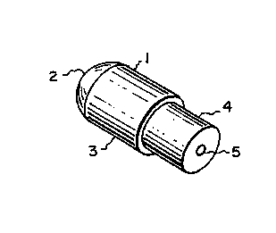
~ IG. 1 illustrates a tool according to
preferred embodiments of the present invention for
making plastic contact lens molds. Tool 1 ~s
constructed of a plastic resin and comprises
optically smooth molding surface 2 as a molding
portion formed on the upper end of cylindrical head
3.
For the embodiment illustrated in FIG. 1, tool
1 comprises a convex molding surface 2.
Accordingly, the tool is designed to form a negative
concave molding surface on multiple plastic contact
lens molds. In turn, contact lenses can be produced
in the plastic molds by conventional methods such as
spincasting, static casting, or spincasting followed
by lathe cutting one lens surface, wherein the
WO ~/~7~ ~ 8 3 -8- PCT/US93/05807
convex lens surface of the contact lenses is formed
from the concave molding surface of the plastic
contact lens molds.
This preferred production sequence is
illustrated in FIG. 7. It will be appreciated that
for this production sequence, the molding surface of
the tool has a shape which substantially corresponds
to a surface of the resultant contact lens. Thus,
in forming a convex toric contact lens surface, the
molding surface of the plastic tool would also have
a convex toric shape. The term "substantially
corresponds" is preferred to define this
relationship between the shape of the tool molding
surface and the shape of the contact lens surface
since the exact shape of the contact lens surface
may deviate slightly from the shape of the tool
molding surface due to such factors as shrinkage of
the thermoplastic contact lens molds prior to
casting contact lenses in these molds. Preferably,
the molding surface of the tool also has a diameter
which substantially corresponds to a diameter of the
resultant contact lens surface, although the molding
surface may be sized to define only a central zone
of the contact lens surface.
To further illustrate the present invention, a
representative plastic mold assembly for static
casting a contact lens is illustrated in FIGs. 2 and
3. Mold assembly 20 comprises generally cylindrical
first mold 21 and generally cylindrical second mold
22. First mold 21 includes concave molding surface
23 and second mold 22 includes convex molding
surface 24. When the mold parts are assembled as
shown in FIG. 3, surfaces 23, 24 define cavity 25 in
which contact lens-l~ is molded. For the embodiment
shown in FIG. l, tool 1, which comprises convex
_
-
W094/07684 PCT/US93/05807
_g_
molding surface 2, is suitable for the injection
molding of first mold 21 wherein molding surface 2
of the tool is used to form molding surface 23 of
the first mold.
The plastic contact lens molds may be molded
from plastic resins known in the art, including
thermoplastic resins such as polypropylene. The
present method for making plastic contact lens molds
differs from conventional methods in that the master
mold, in which the plastic contact lens molds are
formed, includes the plastic tool of the present
invention; otherwise, the plastic contact lens molds
are formed by methods which are known in the art.
For example, tool l of the described preferred
embodiment may be provided with cylindrical lower
base 4 such that the tool takes the form of an
injection molding pin, and cavity 5 is provided for
mounting the tool in the injection molding apparatus
used to mold the plastic contact lens mold. As a
further example, the tool of the present invention
may be used as an optical insert in conjunction with
a mold sleeve. Any other tools constituting the
master mold may be formed of metal as in
conventional molding methods.
For the embodiment illustrated in FIG. 1, the
tool is formed entirely of a plastic resin, in which
case the tool can be lathe cut from rods of the
plastic. For example, head 3 and lower base 4 can
be lathed from rods of the plastic to a desired
diameter to form a "blank" of the tool, i.e., the
head is generally cylindrical and does not yet
n include the molding surface. The molding surface
can then be generated on the tool. A further
advantage of the present invention is that methods
known for providing an optical surface to contact
W O 94/07684 PC~r/US93/05807
2145 6 8 3 -lo-
lens buttons can be employed to generate the desired
molding surface on the tool. For example, a toric
surface can be generated on surface 2 by lathe
cutting, such as the method disclosed in U.S. Patent
~o. 4,680,998 (Council, Jr.), the disclosure of
which is incorporated herein by refer~nce. For this
process, lower base 4 of tool 1 can ~è~mounted in a
lathe chuck for the lathing operation.
As an alternate method of making tool 1, a
tool-shaped article having a generally spherically
curved molding portion can be injection molded.
Subsequently, a desired molding surface, such as a
toric surface or surface having zones of different
curvature, can be generated on the tool by laser
ablation. Excimer laser ablative photo~ecomrosition
(APD) t~chn;ques, in general, are known in the art,
such as the APD method disclosed in U.S. Patent No
5,061,342 (Jones). A preferred method of generating
a desired surface on the tool of the present
invention is the "center-to-edge" excimer laser APD
method described in commonly assigned application
U.S. Serial No. (entitled "Scanning Technique
for Laser Ablation", filed concurrently, attorney
docket no. P01107), the disclosure of which is
incorporated herein by reference. According to this
method, the surface of the tool is ablated while
also removing deposited and adhered debris from the
surface. The method comprises the general steps of:
directing a beam of pulsed W radiation at the
centerpoint of the molding surface: sc~nn;~g in a
direction away from the centerpoint and towards the
edge of the molding surface; rotating the tool 180
degrees; returning the beam to the centerpoint of
the surface; and directing the beam in a direction
~ W094/07684 2 1 ~ 5 6 8 3 PCT/US93/05807
away from the centerpoint to the other edge of the
surface.
FIG. 4 illustrates an alternate embodiment
wherein tool 6 comprises an optically smooth concave
molding surface 7 and cylindrical base 8 which
includes cavity 9. Tool 6 is constructed entirely
of a plastic resin and may be incorporated in a
master mold as an optical insert used in conjunction
with a sleeve. Since tool 6 has a concave molding
surface, this embodiment is designed to form the
negative convex molding surface on multiple plastic
contact lens molds, and in turn, the plastic contact
lens molds form concave lens surfaces of contact
lenses. As an example, tool 6 can be employed to
form molding surface 24 of second mold 22 shown in
FIGs. 2 and 3. A representative production sequence
is illustrated in FIG. 8.
A further embodiment is illustrated in FIGs. 5
and 6. Tool 11 is formed of a plastic resin and
includes molding surface 12 as a molding portion of
head 13. Tool 11 has the form of an insert which
nests with metal support 14. Support 14 includes
cavity 15, similar in function to cavity 5 of tool
1. Tool 11 in conjunction with its support may be
employed for molding processes which employ higher
molding pressures. In higher pressure applications,
tool 11 is less likely to deform during the molding
process than a larger tool such as the embodiment
shown in FIG. 1.
For this alternate embodiment, metal base 14
can be machined by known methods, and head 13 is
preferably injection molded. A desired optically
smooth molding surface 12 is then generated 7.'y the
above-described lathing or laser ablation
tech~; ques.
W O 94/07684 2~ ~5 ~83 PC~r/US93/05807 ~
-12-
In each of the above-described embo~;mPnts, the
tool having the optical surface is made of an
engineering plastic resin which can withstand the
temperature and pressure conditions during molding
of the plastic contact lens molds. For injection
molding~ the resin should have a heat deflection
~emr~rature of at least 350~C and a hardness of at
least 100 on the Rockwell Hardness scale (M scale).
As an additional consideration, the plastic resin
must be suitable for the method employed to generate
a desired surface on the plastic tool. Preferably,
the resin has a hardness in the range of 100 to 125
on the M scale so that the surface of the tool can
be lathed or laser ablated. While various filled
resins meet the above heat and pressure criteria,
generally, an optically smooth surface cannot be
lathed on articles made of filled resins.
Contemplated plastic resins include the following:
engineering plastics based on polyetherimide resins
(such as Ultem~ available from General Electric Co.,
Polymers Product Dept.); polyamide-imide plastics
(such as Torlon available from Amoco Performance
Products); polyphenylene sulfide plastics (such as
Ryton~ available from Phillips Petroleum Co.);
polysulfone and polyarylsulfone plastics (such as
Udel~ and Radel~ available from Amoco Performance
Products): polythalamide plastics (such as Amodel
available from Amoco Performance Products);
polyketone plastics (such as Kadel~ available from
Amoco Performance Products); and various liquid
crystal polymer resins (such as Xydar~ available
from Amoco Performance Products). An Ultem type
resin is especially preferred, and a tool _
constructed of this plastic resin can be used for
injection molding multiple polypropylene contact
~ W 0 94/07684 ~1~5683 PC~r/US93/0~807
lens molds. Additionally, it has been ~ro~trated
that Ultem can be lathe cut or ablated by the above-
described center-to-edge excimer laser ablation
techn;que to generate a desired optically smooth
molding surface on the tool, including a toric
surface.
Although preferred embodiments of the invention
have been described in detail, it will be understood
by those skilled in the art that variations are
within the concept of the invention. For example,
the tool may be provided in any overall shape
suitable for forming the optical surface on the
plastic molds.
.