Note: Descriptions are shown in the official language in which they were submitted.
21 4 S 71 3 EXPRESS MAIL NO.
Descr;pt;on
ENVIRONMENTALLY INSENSITIVE PAPER GUIDE FOR
STRIP CHART RECORDERS
Techn;c~l F;el~
This invention relates to the field of strip
chart recorders, and in particular, to a passive paper
guide for guiding a strip of paper from a strip chart
recorder through a radius of curvature so that the paper
can be environmentally protected by an overlying cover.
Backgrol]n~ of the Inventlon
Several characteristics are important in mobile
electronic devices. Among these are durability,
simplicity, resistance to environmental conditions, low
cost and low weight. Commonly, such electronic devices
incorporate display devices, such as printers, for
providing a visual image of data present in the devices.
One area where this is useful is in devices used for
electronic monitoring of patients in medical situations.
A strip chart recorder is often employed to
provide a printed record, particularly for medical
electronic devices. As data is output, a continuous
stream of paper output is produced. This can occur, for
example, when continuously monitoring a patient's
physiological responses.
In mobile devices intended for use with exposure
to all kinds of environmental conditions, inclusion of a
paper output can provide easy access for moisture and
other cont~m;n~nts which can impair device performance.
In particular, if the paper strip becomes moist at, or
near, the printing location, the printing process can be
significantly impaired. Moreover, when the paper becomes
moist, drag between the paper strip and any surfaces with
which it comes in contact may be increased significantly.
2145713
This can disrupt the flow of paper and cause bunching or
jamming of the output paper stream.
One possible technique for reducing this problem
is to output the paper strip from the bottom of the mobile
device. This can lower the likelihood that moisture in
the form of rain or condensation will enter the device
from above. However, this technique is impractical where
the mobile device may be used on surfaces with debris or
water build-up. Further, an output paper stream from the
bottom of the device is often less accessible to the
operator than a paper stream from the top or side o~ the
device.
Regardless of which location is chosen for the
output, the paper strip must be delivered from its supply
location to an accessible output location where the data
on the paper can be viewed and a length of paper can be
removed from the device. Preferably, paper can be
supplied from within the device from a source located near
to the output to minimize the problems of transporting the
paper. Because size, weight and other design constraints
of mobile devices may limit the feasibility of locating
the paper source near the output, this may not always be
achievable. As a result, the paper strip often must be
directed through some distance before exiting the device.
Even where proximate location is feasible, some
redirection of the paper strip may be desirable to allow
the paper strip to be output at a desired location and
angle.
Due to the lack of substantial rigidity in
typical paper strips, transportation of the paper strip
from the paper source to an output location presents
problems. An extended length of paper is not easily
pushed across any substantial distance, either upwardly or
laterally, without significant bending. This presents a
difficulty analogous to trying to push on a string.
Rather than traveling toward the output, the paper doubles
2145713
over itself. Increasing the pressure on the paper strip
provides no benefit.
The paper strip's lack of substantial rigidity
becomes even more problematic when the paper is to be
directed through a defined angle of curvature from an
upward direction toward the output location. As the paper
is bent through the angle, the upward force on the paper
strip is not transmitted well through the curve and does
not translate into a lateral longitudinal force.
Consequently, increasing upward longitudinal force serves
only to increase the bending problem in the paper causing
deviation from the desired angle of curvature.
One approach to these problems of delivering the
paper strip from within the device to an output location,
either laterally or vertically located with respect to the
paper source is a mechanical aid such as mechanical
rollers, either free or actively driven by the device. In
mobile devices, this may result in added complexity and
weight. It may also increase the difficulty of replacing
a paper source in the field.
Alternately, the paper source may be designed
such that the paper exits the paper source in
substantially the same direction as the paper output. A
lower support can be used supplementally to limit paper
sagging. Where paper drag along the lower support is
significant, this approach may still result in paper
bunching. Moreover, because the paper stream usually must
pass a printing element, such as a thermal printhead, the
paper source orientation may be dictated by considerations
relating to the printing source. For example, it may be
desirable to pass the paper stream past the printhead
vertically to minimize debris build-up between the
printhead and the paper stream or to reduce effects of
vertical forces, such as gravity or vibration.
In such cases, it is often desirable to use a
mechanical guiding system which redirects the paper stream
from the output of the printing source through a radius of
- 2145713
curvature toward the desired output location. Addition of
a mechanical guide often adds weight and complexity to the
device. Further, as the paper stream is directed through
a radius of curvature, it rubs along one surface of the
guide. Friction between the paper stream and a surface of
the guide may cause bunching of the paper stream,
resulting in a paper jam within the guiding mechanism.
Sllmm~ry of the Inventlon
The present invention addresses the problems of
added weight, complexity, environmental sensitivity, and
reliability by providing a passive paper guide integrated
within the device unit and/or a device cover.
The inventors have discovered that directing the
paper strip toward an initially parallel curved surface
allows the paper strip to be passively guided through a
defined radius of curvature. An appropriately chosen
radius of curvature defined by substantially parallel
upper and lower walls permits the paper strip to be guided
through an angle and across a substantial distance. The
paper strip can thus be directed and transported from a
paper source within the device body to an output aperture.
The integrated passive paper guide directs an
output paper strip through a radius of curvature toward a
desired output aperture using guide walls containing
ridges for friction minimization. The reduced surface
area of contact between the guide surface and the paper
stream reduces the problems associated with paper wetness
and cont~m'n~nt buildup.
The problem of paper wetness is further reduced
by directing the paper strip through an output aperture
placed on the side of the device. The output aperture on
the side of the device is shielded from environmental
effects by an output aperture cover. The output aperture
cover can also function as a latch to secure the device
cover to the device.
-
- 2145713
In one embodiment, the inventive device further
reduces complexity and weight by integrating the upper
surface of the passive paper guide into the device cover
and the lower surface of the passive paper guide into the
topography of the upper surface of the device. A gap is
formed between the upper surface of the paper guide and
the lower surface of the paper guide when the
environmentally protective device cover is in place. The
paper strip is guided by the passive paper guide through
the gap toward the output aperture, beneath the output
aperture cover. The output aperture cover in one
embodiment functions also as a cover latch.
The edges of the device cover in one embodiment
form a seal when mated with the device unit, thereby
leaving a gap only in the location of the paper output
aperture to environmentally protect the device. The paper
output aperture cover overhangs the edge of the output
aperture, providing some shielding from environmental
effects.
The paper output aperture cover in the preferred
embodiment is shaped such that a paper-tearing ridge is
formed along its distal end, permitting it to function
also as a paper-tearing aid.
Br;ef Descr;pt;on of the Dr~w;ngs
Figure 1 is an isometric view of a portable
defibrillator incorporating the inventive paper guide.
Figure 2 is an isometric view of the portable
defibrillator of Figure 1 shown with a protective cover in
its open position.
Figure 3 is a side cross-sectional view of a
portion of the defibrillator of Figure 1 incorporating the
inventive paper guide.
Figures 4A-B are detailed isometric and cross-
sectional views, respectively, of the upper portion of thepaper gulde.
-- 21~5713
Figures SA-B are detailed isometric and cross-
sectional views, respectively, of the lower portion of the
paper guide.
Figure 6 is an isometric detail view of the
latch cover.
Peta;led nescr;ption of the Invent;on
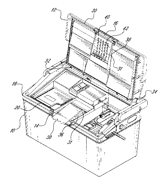
Figures 1 and 2 show a portable defibrillator
incorporating the preferred embodiment of the present
invention. The mobile electronic unit contains a body 10
and a cover 12. Incorporated in the cover 12 is an
aperture 14 above which is located on aperture cover 16.
The cover 12 mates with an upper part 18 of the
body 10 along an interface 20 (Figure 2). In one
embodiment of the device, the interface 20 forms an
environmentally insensitive seal limiting passage of
environment impact between the cover 12 and the upper part
18.
As can be seen from Figure 2, the output
aperture cover 16 provides a passage through which a paper
strip 30 may pass. The cover 12 of the preferred
embodiment is rotatably mounted to the upper part 18 by
hinges 32, 34. Other configurations and mounting
techniques will be obvious to those skilled in the art.
The paper strip 30 is guided by a paper guide 31
including an upper guide 38 having a guide surface 42
integrated into the cover 12 and a lower guide 36
incorporated in the upper part 18. Friction between the
paper strip 30 and the guides 36 and 38 is reduced by
inclusion of ridges 40 on the guide surface 42 of the
upper guide 38 and on the lower guide 36. The ridges 40
are preferably longitudinal to direction of movement of
the paper strip 30. Figure 2 shows the upper guide 38
containing five longitudinal ridges 40; however, an
alternate number of ridges may be chosen depending on the
paper width, paper characteristics, and other design
-- 2145713
considerations. Moreover, a paper guide with no ridges is
within the scope of the present invention.
Figure 3 shows a cross-sectional view of the
device of Figure 1 with the cover 12 in a closed position.
When the cover 12 is in this closed position, a gap 48
remains between the longitudinal ridges 40 on the guide
surface 42 of the upper guide 38 and a guide surface 50
of the lower guide 36. The gap 48 extends from the output
aperture 14 to a lower body exit 52. Within the device
body 10 is a paper spool 56 operating as a paper source.
As further shown in Figure 3, the paper strip 30
exits from the paper spool 56 through paper drive spools
62, 64. The paper drive spools 62, 64 are presented in
simplified fashion in Figure 3 as circular cross-sections.
Such drive mechanisms typically require an opposing spool
or an opposing surface (not shown). Such paper drive
mechanisms are known in the art.
The paper strip 30 exits the device body 10
through the lower body exit 52 and is guided through a
radius of curvature R by the guide surface 50 of the lower
guide 36 and the longitudinal ridges 40 incorporated in
the upper guide 38. The paper strip 30 continues through
the gap 48 toward the output aperture 14 passing below the
output aperture cover 16. The output aperture cover 16
contains an edge 66 which can operate as a paper-tearing
aid.
Figures 4A and B show the upper guide 38 in
greater detail. As shown in Figure 4B, the ridges 40 are
incorporated directly into the upper guide 38. The
longitudinal ridges 40 comprise protrusions with rounded
edges to provide a surface having a relatively small area
of contact with the paper strip 30 (not shown in Figure
4B). Alternately, other topographies may be chosen to
conform to specific manufacturing and design
considerations in any given case. Further, the
longitudinal ridges 40 may be discrete structures mounted
-- 2145713
on the device cover 12 rather than being integrated into
the upper guide 38 itself.
As shown in Figures 5A and B, the lower guide 36
may also incorporate a set of longitudinal ridges 68. It
is preferred that the lower set of longitudinal ridges 68
be in alignment with respect to the upper ridges 40,
although other orientations may be chosen. As shown in
Figure 5B, the set of longitudinal ridges 68 on the lower
guide portion 36 have a similar topography to the
longitudinal ridges 40 on the upper guide portion 38,
except that the lower set of longitudinal ridges 68 extend
upwardly from the guide surface 50 of the lower guide 36
rather than downwardly from the guide surface 42 of the
upper guide 38.
In the preferred embodiment of Figures 4 and 5,
five ridges 40, 68 are used having heights and widths of
approximately 0.1 inch, and an edge radius of curvature of
0.375 inch. However, different ridge heights, ridge
widths, numbers of ridges and ridge edge radii are within
the scope of the invention.
Figure 6 shows in detail a preferred embodiment
of the aperture cover 16 mounted rotatably to the cover 12
around an axis 70 releasably to engage a catch block 72.
In this embodiment, the protrusion 68 comprises a
relatively sharp edge to aid in tearing the paper strip
30. Lower extensions 74, 76 of the aperture cover 16
engage the catch block 72 at edges 78, 80, allowing the
output aperture cover 16 to function as a latch. Catch
blocks 72, 73 are mechanically attached to the device body
10 (not shown).
When the cover 12 is in the closed position,
bias springs 60 bias the lower protrusions 74, 76 against
the extensions 78, 80 of the catch blocks 72, 73 such that
the aperture cover 16 remains engaged with the catch
blocks 72, 73. The aperture cover 16 may be disengaged
from the catch blocks 72, 73 by applying upward pressure
to overcome the bias of the bias spring 60 and rotate the
- -- 2145713
aperture cover 16 around the axis 70 in a clockwise
direction.
Operation of the preferred embodiment of the
inventive device will now be explained with reference to
Figure 3. When the device is in operation, the paper
strip 30 exits the paper spool 56 and is driven by the
paper drive spool 62 toward the lower body exit 52.
Located within the device body 10 is a printing element
~not shown) at which the paper strip 30 is directed by the
paper drive spool 62. Information is recorded on the
paper strip 30 as it passes the printing elements (not
shown) in a manner well known in the art.
The paper strip 30 then travels to the lower
body exit 52. After passing through the lower body exit
52, the paper strip 30 enters the gap 48 and is directed
through a radius of curvature R, typically through an
angle of approximately 90. Within the gap 48, friction
between the paper strip 30 and the paper guides 36, 38 is
minimized through the use of rounded ridges 40 and 68,
which reduce the surface area of contact between the paper
strip 30 and the guides 36, 38. The paper strip 30 exits
the guides 36, 38 at the aperture 14 passing under the
output aperture cover 16. In this manner, a continuous
paper strip 30 can be produced.
In some cases, it may be desirable to tear off a
portion of the paper strip 30. This can be done by
cutting or tearing the paper strip 30 using the sharpened
edge 66 in the aperture cover 16. A user can tear the
paper strip 30 by applying sufficient upward force on the
paper strip 30 against the sharpened edge 66. Though the
sharpened edge 66 is shown in Figure 3 as being placed
above the output aperture 14, the sharpened edge 66 may be
located elsewhere on the cover 12, or on the body 10.
Although preferred embodiments of the present
invention have been described, it will be understood that
the invention is not limited to the embodiments disclosed,
but is capable of numerous arrangements, modifications,
-- 2145713
and substitutions of parts and elements without departing
from the spirit of the invention. Accordingly, the
invention is not limited except as by the appended claims.