Note: Descriptions are shown in the official language in which they were submitted.
214 6 0 3 ~ SC-5254-C
FUSE ASSEMBLY WITH LOW EXHAUST AND REPLACEABLE CARTRIDGE
BACKGROUND OF THE INVENTION
1. Field of the Invention
The present invention relates generally to current-interrupting devices for
electrical
power distribution systems and more particularly to a low-exhaust composite
drop-out fuse
assembly that is usable with a standard cutout mounting, provides current-
limiting
characteristics, and includes a low-current clearing section that is simply
and economically
renewable for reuse.
2. Description of the Related Art
Various assemblies and devices have been proposed to provide current
interrupters in
electrical power distribution circuits that have reduced exhaust
characteristics as compared to
distribution cutouts with replaceable fuse links. The class of expulsion fuses
known as cutouts
have undesirable exhaust characteristics that are well known in the industry
and discussed in
the literature, e.g. see ANSI/IEEE standard C37.48 and the U.S. Patents
discussed herein.
One approach to reduce the exhaust of expulsion devices as set forth in U.S.
Patent No.
3,863,187 provides the series connection of a current limiting fuse with a
conventional cutout.
The current limiting fuse is connected to one of the terminals of the cutout
mounting and is not
part of the drop-out fuse tube assembly. While this approach does reduce the
exhaust
characteristics of the cutout and also provides current limiting of the faults
in the circuit, it
also has undesirable characteristics regarding installation and maintenance.
Specifically, the
current limiting fuse is difficult to replace from a distance which requires
the lineman to either
deenergize the lines or come in close proximity to energized lines. Obviously,
since safety of
operating personnel is an important essential of any product use, neither
alternative is readily
acceptable. Since there is no provision to easily determine whether or not the
current limiting
fuse has operated, this requires the difficult servicing procedure every time
that the cutout
operates and drops out.
Other approaches are directed to the provision of a composite or combined
assembly
some of which are of the drop-out type. These composite assemblies provide a
single
assembly or device that is the combination of a current limiting fuse with
another lower-
current fuse or cutout. For example, approaches of this type are shown in U.S.
Patent Nos.
-1-
214 6 0 3 ~ SC-5254-0
3,893,056, 5,274,349, 4,011,537, 3,827,010, 4,184,138, 4,114,128, 4,121,186,
4,161,712
and 2,917,605.
The arrangement of U.S. Patent No. 3,893,056, which is not directed to a drop-
out
assembly or a disconnect mounting, utilizes the interior of the current
limiting section to
accommodate operational portions of the expulsion fuse section such as the
arcing rod or a
muffler portion. However, the fuse sections are not separable and the
expulsion fuse is a one-
shot device that does not have provisions for refusing.
A current-limiting drop-out fuse is shown in U.S. Patent No. 5,274,349. This
arrangement is not vented (no exhaust provisions) and also includes a low-
current clearing
section. Unfortunately, the entire one-piece fuse body must be replaced after
all types of
operation, i.e. even after clearing low-range overcurrents.
The other aforementioned composite or combined assemblies (e.g. as shown in
the
aforementioned U.S. Patent Nos. 4,011,537, 3,827,010, 4,184,138, 4,114,128,
4,121,186,
4,161,712 and 2,917,605) also provide some desirable features but suffer from
one or more
drawbacks. For example, they all utilize expulsion fuse sections of the cutout
type that have
the undesirable exhaust characteristics as a result of open-ended fuse tubes
through which a
fuse-links cable exits. Further, regarding mechanical configuration, these
arrangements all
have the problem of fitting the cutout fuse tube and the current-limiting fuse
within the straight
line distance between the mounting terminals. While the composite fuse
assembly of the
aforementioned U.S. Patent No. 4,184,138 provides a cutout fuse tube at an
angle to the
current-limiting fuse such that the combined lengths of the two sections may
be somewhat
greater than the straight line distance, this configuration still results in a
very short length that
is available for the cutout fuse tube. The remainder of the aforementioned
arrangements
utilize in-line configurations of the cutout fuse tube and the current-
limiting fuse such that the
available length must be divided between the two devices. Additionally, some
of the
aforementioned arrangements are not usable with existing standard cutout
mountings which
would require the purchase and installation of new mountings throughout a
distribution system.
While the prior art arrangements may be useful to provide combinations of
current
interrupting devices with other devices, none of these previous approaches
provides a desirable
commercial replacement for a distribution cutout, namely a drop-out assembly
with low
exhaust characteristics that is usable in a standard cutout mounting and that
allows the current-
limiting section to be reused when only the low-current section has operated.
-2-
214 6 0 3 ~ SC-5254-0
SUMMARY OF THE INVENTION
Accordingly, it is a principal object of the present invention to provide a
composite
drop-out fuse assembly with current-limiting and low-exhaust characteristics
that is usable with
a standard cutout mounting and includes a low-current section that is capable
of reuse after a
simple refusing operation.
It is another object of the present invention to provide a drop-out fuse
assembly for a
standard cutout mounting that includes a current-limiting section and a
refusable low-current
clearing section having low exhaust characteristics.
It is a further object of the present invention to provide a drop-out current-
interrupting
assembly for a standard cutout mounting with a side-by-side configuration of a
current limiting
section and a refusable low-exhaust current-clearing section.
It is yet another object of the present invention to provide a separable fuse
tube
assembly for a composite drop-out assembly for use in a standard cutout
mounting wherein the
fuse tube assembly includes a pivotable release feature that is adjacent the
upper terminal of
the cutout mounting and that is responsive to operation of a fuse cartridge
carried by the fuse
tube assembly to release the composite drop-out assembly from the cutout
mounting via the
pivoting of the composite drop-out assembly with respect to the lower terminal
of the cutout
mounting.
It is another object of the present invention to provide a separable current-
limiting
section for a composite drop-out assembly for use with a cutout mounting, the
current-limiting
section including exhaust control and venting provisions for a low-current
clearing section of
the composite drop-out assembly.
It is a further object of the present invention to provide a composite drop-
out fuse for
use with a cutout mounting including a first section being generally tubular
and housing a first
fusible element and a second section being a generally flat polyhedron and
housing a second
fusible element, the two sections being assembled in a predetermined side by
side
configuration and including arrangements to connect the first and second
fusible elements in an
electrical series circuit and to connect the series circuit between the upper
and lower terminals
of the cutout mounting.
These and other objects of the present invention are efficiently achieved by
the
provision of a low-exhaust composite drop-out assembly that is utilizable in a
standard cutout
mounting in electrical power distribution systems. The composite drop-out
assembly includes
current-limiting and low-current clearing sections and is easily removable
from the mounting
for servicing. The sections are efficiently arranged in a side by side
configuration. The low-
current clearing section includes a fuse-tube assembly having a replaceable
fuse cartridge.
-3-
214 6 0 3 5 SC-5254-0
Accordingly, the low-current clearing section is simply and economically
renewable for reuse
whether or not the current-limiting section has operated. Further, the current-
limiting sectio~l
need not be replaced if only the low-current clearing section operated in
response to
overcurrent in a low range. Additionally, the sections are separable so that
the low-current
clearing section can be reused after simple refusing even when the current-
limiting section has
operated.
BRIEF DESCRIPTION OF THE DRAWING
The invention, both as to its organization and method of operation, together
with
further objects and advantages thereof, will best be understood by reference
to the specification
taken in conjunction with the accompanying drawing in which:
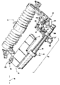
FIG. 1 is a perspective view of a composite drop-out fuse in a standard cutout
mounting in accordance with the principles and features of the present
invention;
FIG. 2 is an exploded view of the components and assemblies of the composite
drop-
out fuse of FIG. 1 and illustrating assembly/disassembly for refusing;
FIG. 3 is a front elevational view of the composite drop-out fuse of FIGS. 1
and 2,
partly in section and with parts removed and cut away for clarity;
FIGS. 4 and 5 are respective front elevational and top plan views of a movable
contact
arm of the composite drop-out fuse of FIGS. 1-3;
FIG. 6 is a bottom plan view of an upper ferrule of the composite drop-out
fuse of
FIGS. 1-3;
FIG. 7 is a sectional view taken along the line 7-7 of FIG. 6;
FIG. 8 is an elevational view of a spring/cable assembly of the composite drop-
out fuse
of FIGS. 1-3 with parts cut away for clarity; ,
FIG. 9 is an elevational view of a fuse cartridge of the composite drop-out
fuse of
FIGS. 1-3 with parts cut away for clarity;
FIGS. 10, 11, and 13 are respective front, right side and bottom elevational
views of a
fuse tube of the composite drop-out fuse of FIGS. 1-3;
FIG. 12 is a sectional view taken along the line 12-12 of FIG. 10;
FIGS. 14 and 16 are respective front elevational and bottom plan views of a
limiter
assembly of the composite drop-out fuse of FIGS. 1-3;
FIG. 15 is a sectional view taken along the line 15-15 of FIG. 14;
FIG. 17 is a sectional view taken along the line 17-17 of FIG. 14;
FIGS. 18-20 are respective rear, front, and right-side elevational views of a
cover for
the limiter assembly of FIGS. 14-17;
-4-
2146035
SC-5254-C
FIGS. 21-24 are sectional views taken respectively along the lines 21-21, 22-
22, 23-23,
and 24-24 of FIG. 18;
FIGS. 25-27 are respective front, top-plan, and left-side elevational views of
a trunnion
of the composite drop-out fuse of FIGS. 1-3 fits into the lower hinge of a
standard cutout
mounting;
FIG. 28 is a sectional view taken along the line 28-28 of FIG. 26;
FIG. 29 is a partial sectional view taken along the line 29-29 of FIG. 14;
FIG. 30 is an elevational view of a fusible element support for use with the
limiter
assembly of FIGS. 14-17;
FIG. 31 is a plan view of a portion of the fusible element of the composite
drop-out
fuse of FIGS. 1-3;
FIG. 32 is a sectional view similar to FIGS. 14 and 15 illustrating an
alternate
exhaust/venting section of the limiter assembly;
FIG. 33 is a partial right-side elevational view, on an enlarged scale, of the
lower
portion of the exhaust/venting section of the limiter assembly of FIG. 14;
FIG. 34 is a partial sectional view, on an enlarged scale, taken along the
line 34-34 of
FIG. 16; and
FIG. 35 is a partial sectional view, on an enlarged scale, taken along the
line 35-35 of
FIG. 14.
DETAILED DESCRIPTION
Referring now to Fig. 1, a composite drop-out fuse 10 of the present invention
as
illustrated in a standard cutout mounting 12 provides full range protection
according to a
predetermined time-current characteristic curve so as to limit fault currents
and interrupt the
circuit while exhibiting low exhaust characteristics. The cutout mounting 12
is of the type as
illustrated in U.S. Patent No. 4,414,527 and is adapted to mount a fuse tube
with installed
fuse link as is commonly used throughout electrical power distribution
systems. The
composite drop-out fuse 10 includes a low-current section generally referred
to at 14 and a
current-limiting section generally referred to at 16 which are connected in
electrical series-
circuit relationship and physically arranged in a generally side by side
configuration. In
response to overcurrents (faults) in a low range that do not exceed a
predetermined level, only
the low-current section 14 operates to interrupt the current whereupon after
location and
correction of the condition causing the overcurrent, the low-current section
14 can be refused
as will be explained in more detail hereinafter. For overcurrents (faults)
that exceed the
predetermined level, i.e. high range overcurrents, the current-limiting
section 16 limits the
-5-
2146035
SC-5254-C
overcurrent and the low-current section 14 operates to interrupt the
overcurrent. For these
high-range overcurrents, the current-limiting section 16 requires replacement
and the low-
current section 14 requires refusing.
In accordance with important aspects of the present invention and with
additional
reference now to FIGS. 2 and 3, the current-limiting section 16 is provided by
a limner
assembly 17 and the low-current section 14 is provided by a fuse tube assembly
15 along with
portions of the limiter assembly 17 which provide exhaust control and venting
functions which
will be explained in more detail hereinafter. The limner assembly 17 and the
fuse tube
assembly 15 include cooperating features and interfitting arrangements for the
assembly into
the composite drop-out fuse 10 having a predetermined configuration as shown
in FIGS. 1 and
3 and for providing the series electrical interconnection of the sections 14
and 16. The limiter
assembly 17 includes a trunnion arrangement 18 that interfits with a lower
mounting contact
arrangement 20 of the mounting 12 so as to support the composite drop-out fuse
10 and
provide electrical connection. The fuse tube assembly 15 includes an upper
contact assembly
22 that cooperates with a spring contact 24 of an upper mounting contact
arrangement 25 of
the mounting 12 so as to retain the composite drop-out fuse 10 within the
mounting 12 and
provide electrical connection.
The upper contact assembly 22 also includes a pull ring assembly 26 defining a
pull
ring 35 which may be engaged by a hookstick (not shown) or a portable
loadbreak tool (not
shown) to move the upper contact assembly 22 away from the upper contact of
the mounting
12 while the trunnion and lower contact arrangement 18 rotates in the lower
contact or hinge
20 of the mounting 12, the portable loadbreak tool being required to open the
composite drop-
out fuse 10 unless the circuit is deenergized. The cutout mounting 12 also
includes attachment
hooks 27 for use with a portable loadbreak tool. The composite drop-out fuse
10 also includes
a release feature which provides for the drop out of the composite drop-out
fuse 10 upon
operation of the low-current section 14 such that the composite drop-out fuse
10 moves from
the position as shown in FIG. 1 to a drop out position similar to the position
assumed by
cutouts upon operation and the same as the composite drop-out fuse when opened
and rotated
by a hookstick or the like, with the fuse tube assembly 15 moving to the
position as illustrated
by the axis generally referred to at 19 in FIG. 1. The release feature is
provided by a movable
contact arm 28, the details of which are best illustrated in FIGS. 4 and 5.
The movable
contact arm 28 is carried by and pivotally mounted with respect to the fuse
tube assembly 15 at
a pivot point 29. A pivot pin 31 is carried through a collar 33 of the pull
ring assembly 26 to
pivotally mount the movable contact arm 28 at the pivot point 29. At one end
remote from the
pivot point 29, the movable contact arm 28 is provided with a contact 30 which
is generally
convex and suitably contoured and shaped to interfit with a generally concave
indentation 24a
-6-
214 6 0 3 ~ SC-5254-0
as found in the standard cutout mounting 12, such that the contact 30 fits
into and is held by
the indentation 24a and suitable electrical contact pressure is maintained
between the spring
contact 24 and the contact 30. The contact arm 28 also includes a contact
finger 32 at a
second end of the contact arm 28 on the opposite side of the pivot point 29
from the contact
30. The contact finger 32 is captured within a guide channel or surface 34
that is formed by
an extending portion 36 of an upper ferrule 38 of the upper contact assembly
22, the details of
the upper ferrule being best illustrated in FIGS. 6 and 7. The contact arm 28
is fabricated to
provide a suitably conductive path from the spring contact 24 to the upper
ferrule 38. The
upper ferrule 38 is movably mounted with respect to the fuse tube assembly 15
as will be
explained in more detail hereinafter.
Upon operation of the low-current section 14 in response to overcurrents, the
upper
ferrule 38 moves upward such that the portion 36 assumes the position shown in
phantom in
FIG. 3 as 36' . As the upper ferrule 38 moves upwardly, the contact finger 32
moves along
the surface from 34a to 34b whereupon the contact arm 28 pivots to the
position shown in
FIG. 2. The pivoting of the contact arm 28 (counterclockwise in FIG. 1)
shortens the overall
length of the composite drop-out fuse 10 from the trunnion 18 to the contact
30 resulting in the
release of the composite drop-out fuse 10 to pivot or rotate from the closed
position in FIG. 1
to the drop out position. To aid in closing the composite drop-out fuse 10 and
supporting the
composite drop-out fuse 10 within the mounting 12, the fuse tube assembly 15
includes a
guide/support arm 40 extending therefrom which is arranged to fit between the
attachment
hooks 27 and stop against a central portion of the attachment hooks 27. The
collar 33 of the
pull ring assembly 26 is pressed on and affixed to the fuse tube assembly 15
by attachment to
the guide/support arm 40 via a pin or the like 41. Accordingly, the
orientation of the upper
ferrule 38 is suitably controlled via the finger 32 of the contact arm 28
within the guide surface
or channel 34 of the upper ferrule 38, which in turn is fixed in orientation
with respect to
rotation about the fuse tube assembly 15 by the collar 33. It should also be
noted that the
guide surface or channel 34 of the upper ferrule 38 is dimensioned and
contoured along with
the contact forger 32 to ensure after pivoting to a release position, the
contact arm 28 will be
free to pivot in a return direction (clockwise in FIG. 1) as the upper ferrule
returns to its
normal lowered position after moving upward during fuse operation and release
from the
cutout mounting 12. In this way, the fuse tube assembly 15, after refusing, is
ready for use
with appropriate functioning of the contact arm 28.
With the composite drop-out fuse 10 removed from the mounting 12, the fuse
tube
assembly 15 is refused and if required, the limiter assembly 17 is replaced.
To allow refusing
and as shown in FIG. 2, the fuse tube assembly 15 is separable from the limner
assembly 17
via the disassembly of a threaded collar 42 that is carried by the fuse tube
assembly 15 from a
_7_
214 ~ ~ 3 5 SC-5254-C
mating threaded portion 44 of the limiter assembly 17. A threaded cap 46
closes the top of the
upper ferrule 38 of the fuse tube assembly 15 via attachment with a threaded
portion 48 of the
upper ferrule 38. The fuse tube assembly 15 includes a removable spring/cable
assembly 50
and a fuse cartridge 52 which is carried by the spring/cable assembly 50. With
the
spring/cable assembly 50 and the fuse cartridge 52 installed for operation,
the spring/cable
assembly 50 is stretched so as to apply tension to the fuse cartridge 52 which
is affixed at its
lower end to the bottom of the fuse tube assembly 15. When the low-current
section 14
operates, portions of the fuse cartridge 52 melt, vaporize, and become
disintegral. An upper
terminal 54 of the fuse cartridge 52 moves toward the top of the fuse tube
assembly 15
responsive to the tension in the spring/cable assembly 50, separating the
upper terminal 54
from a lower terminal 56 of the fuse cartridge 52. In accordance with well
known principles,
the lengthening of the gap in combination with the release of arc-
extinguishing gases inside the
fuse tube assembly 15 interrupts current flow in the fuse tube assembly 15 at
the time of
current zero in the alternating current wave form. When refusing the fuse tube
assembly 15,
the spring/cable assembly 50 is removed from the fuse tube assembly 15. Next,
the remnants
of the fuse cartridge 52 are removed, namely the upper terminal 54 is
unthreaded from the
spring/cable assembly 50, any particles are removed from the open section of
the limiter
assembly 17 and the interior of the fuse tube assembly 15. A new fuse
cartridge 54 is attached
to the spring/cable assembly 50, and the combination is installed in the fuse
tube assembly 15
by dropping it into the fuse tube assembly 15, extending the lower terminal 56
through the
fuse tube assembly 15 and seating the fuse cartridge 54 in the proper
location, e.g.
accomplished in a specific illustrative embodiment by a flexible attachment
element 58 (FIG.
2) or the like, which is affixed to the lower terminal 56 of the fuse
cartridge 54 and then
removed after installation. The cap 46 is then replaced and the fuse tube
assembly 15 is ready
for installation into service. If the current-limiting section 16 also
operated, as verified by a
continuity check, a new limiter assembly 17 is assembled to the refused fuse
tube assembly 15.
On the other hand, if the limner assembly 17 did not operate, the original
limiter assembly 17
is reassembled onto the refused fuse tube assembly 15.
With reference now to the more detailed aspects of the spring/cable assembly
50 and
with additional reference to FIG. 8, a first end of an extension spring 60 is
affixed to an
interconnection rod 62, for example via a threaded portion 64 of the rod 62
and a portion 66
of the spring 60 with several turns of reduced diameter. The other end of the
extension spring
60 is affixed to a threaded portion 68 of an upper spring ferrule 70. The
upper spring ferrule
70 includes a widened disc-shaped cap portion 72 which is fabricated to be
wider than the
opening 39 of the upper ferrule 38 of the fuse tube assembly 15, for the
purpose of
maintaining the installed spring/cable assembly 50 in the appropriate
position. Each of the
_g_
214 6 0 3 5 SC-5254-C
upper spring ferrule 70 and the interconnection rod 62 include respective
central bores 74,76.
A conductive cable 78 is disposed inside the spring 60 (assembled prior to the
affixing of the
spring 60) that is of sufficient length to accommodate the length of the
extension spring 60 in
its maximum extended operating position. The cable 78 is wound in an opposite
sense to that
of the spring 60. The ends of the cable 78 are affixed to the spring ferrule
70 and the rod 62
via the insertion into the bores 74,76 followed by appropriate process steps,
for example, by
swaging operations. Accordingly, when the spring/cable assembly is in
operative position
within the upper ferrule 38, a suitable conductive path is established from
the upper ferrule 38
to the lower end of the extension rod 62. The extension rod 62 at its lower
end includes a
central threaded bore 80 for use in assembly to the fuse cartridge 52. In a
preferred
embodiment, the rod 62 is fabricated from conductive material. However, in
alternative
embodiments, the suitable conductive path is established to the cable 78 via
any of various
conductive path arrangements through the rod 62.
Referring now to FIG. 9, the upper terminal 54 of the fuse cartridge 52
includes a
threaded top portion 82 to thread into the threaded bore 80 of the rod 60 of
the spring/cable
assembly 50. The lower terminal 56 includes a contact 84 which is utilized to
retain the fuse
cartridge 52 in the fuse tube assembly 15 and provide electrical connection
through the fuse
tube assembly 15 to the limiter assembly 17 as will be explained in more
detail hereinafter. A
loading clip 86 with retainer aperture 87 (also see FIG. 2) is also carried on
the lower terminal
56 to aid in loading/assembling the fuse cartridge 52 into the fuse tube
assembly 15, for
example, via the attachment of the flexible attachment element 58 or the like
as discussed
hereinbefore. A fusible element 88 and a strain wire 90 are each disposed
between and affixed
to the upper and lower terminals 54,56. In a preferred embodiment, the upper
and lower
terminals 54,56 are provided with respective central bores 92,94 into which
the ends of the
fusible element 88 and the strain wire 90 are positioned. The respective end
portions 96,98 of
the terminals 54,56 are then suitably processed and worked, for example by a
swaging
operation, to secure the components 88,90 and provide electrical connection
and a suitable
conductive path.
A sheath 100 of arc-extinguishing material is affixed over the ends of the
terminals
54,56 and suitably secured thereto by a process or working operation, for
example, by the use
of a choke 101 which is swaged on. The sheath 100, in accordance with well-
known
principles and as utilized in fuse links for cutouts, serves to suitably
maintain the integrity of
the fuse cartridge 52 under low overcurrent conditions and burst at
predetermined pressures in
response to predetermined higher overcurrent levels. In this manner, for lower
range
overcurrents and after the fusible element melts, the current then separates
the strain wire 90
and arcing ensues with the sheath 100 remaining intact throughout the current
interruption
-9-
2 ~ 4 ~ ~ 3 ~ SC-5254-C
process and provides the desired pressure to extinguish the arc. At higher
overcurrent levels,
the sheath 100 bursts due to the higher pressures developed by the arcing and
the arc is
extinguished inside the bore of the fuse tube assembly 15.
With regard to additional aspects of the fuse tube assembly 15 and referring
additionally to FIGS. 10-13, the fuse tube assembly 15 includes a fuse tube
102. In the
preferred embodiment, the fuse tube 102 is fabricated in a molding process
from a suitable
thermoplastic (e.g. polycarbonate, polyester, polyamide, polyacetate, etc.)
with all the features
as shown in FIGS. 10, 11 and 13, although in alternative embodiments it should
be realized
that the fuse tube 102 is fabricated by machining the various features or by
affixing/securing of
parts thereon. For example, the guide/support arm 40, is molded as part of the
fuse tube 102.
Additionally, the fuse tube 102 also includes four circumferentially spaced
stiffener/strengthening ribs 104 and various features for cooperating with the
limiter assembly
17 for proper orientation, assembly, and operation of the assembled fuse tube
assembly 15 and
the limner assembly 17. In the specific illustrated embodiment, the lower end
or neck portion
105 of the fuse tube 102 includes locating/orientation protuberances 106 and
108, a widened
sealing flange portion 110, and a recessed area 112 for receiving a contact
arm 114 (FIGS. 2
and 3) that provides electrical connection to the limiter assembly 17. The
fuse tube 102
includes a cylindrical central bore 116 and additional features formed within
the bore 116.
Considering the assembly of the upper ferrule 38 onto the fuse tube 102 of the
fuse
tube assembly 15, the upper ferrule 38 is retained on the fuse tube 102 by a
resilient split ring
162 (FIG. 3). Additionally, the upper ferrule 38 is biased away from the fuse
tube 102
(upwardly in FIG. 3) by the provision of a compression spring 164 (FIG. 3)
which is arranged
between the fuse tube 102 and the inner passage of the upper ferrule 38.
Specifically, the
upper ferrule 38 with the spring 164 and the split ring 162 are assembled onto
the fuse tube
102. The split ring 162 first expands over the widened end portion 166 of the
fuse tube 102
and continues to move along the fuse tube 102 until it reaches the widened
portion 168 of the
fuse tube 102 adjacent the narrowed section 120. At that point, the split ring
162 expands into
the groove 169 of the upper ferrule 38, where it then remains. Thereafter,
while the upper
ferrule 38 can move with respect to the fuse tube 102 and under the bias of
the spring 164, the
upper ferrule 38 is retained on the fuse tube 102 since the split ring 164
prevents the upper
ferrule 38 from moving past the point where the split ring 162 interferes with
the widened
portion 166 at the end of the fuse tube 102.
The fuse tube assembly 15 further includes an arc extinguishing tube 124 that
is
fabricated from suitable arc extinguishing material. The arc extinguishing
tube 124 is
preferably molded into the fuse tube 102 during fabrication. The bore 116 of
the fuse tube
102 also includes a widened lower section with wall and shoulder features at
128 and 130 for
- 10-
214603
SC-5254-0
receiving and retaining a contact 132 in the shape of a ring (annulus). The
assembly of the
contact 132 (e.g. via interference fit) retains the arc extinguishing tube 124
within the fuse
tube 102. The contact arm 114 is affixed to the contact 132 (as shown in FIGS.
2 and 3). As
seen in FIG. 3, when the fuse cartridge 52 is assembled into the fuse tube
assembly 15, the
contact 84 of the lower terminal 56 of the fuse cartridge 52 seats upon and
provides an
electrical connection to the contact 132, the contact arm 114 connected to the
contact 132
providing electrical circuit connection to a terminal connector 140 (FIG. 3)
of the limiter
assembly 17 when the fuse tube assembly 15 is assembled to the limiter
assembly 17 as will be
explained in more detail hereinafter. The contact 132 is fabricated with an
inner surface
contour at 142 and a central shoulder 144 with central aperture 146 to
cooperate with the
contact 84. Specifically, the contact 84 is fabricated with legs 148 (FIGS.
2,3 and 9) that are
resilient and flexible and extend outwardly from the central portion of the
contact 84.
When the spring cable 50 with attached fuse cartridge 52 are positioned
through the top
opening of the upper ferrule 38 and pulled (via the flexible attachment
element 58 as illustrated
in FIG. 2) by stretching of the spring 60 downward through the contact 132,
upon lessening of
the tension in the string/weight attachment 58, the legs 148 move over the
contour surface 142
and seat on the shoulder 144 as shown in FIG. 3 , thus retaining the fuse
cartridge 52 and
attached spring/cable assembly 50 in operative position within the fuse tube
assembly 15, the
cap 72 of the spring/cable assembly 50 being seated atop the exterior of the
upper ferrule 38.
The cap 46 is threaded onto the upper ferrule 38 to close the top of the fuse
tube 102. The
fuse tube 102 is also fabricated to provide a circumferentially defined recess
134 via the
cooperation of the flange portion 110 and notched or reduced height portions
136 of the
stiffener ribs 104. The threaded collar 42 of the fuse tube assembly 15 is
positioned onto the
fuse tube 102 over the lower end and the flange 110 and over the stiffener
ribs 104. A
resilient split ring 138 (FIG. 3) is snapped into place in the recess 134 so
as to retain the
threaded collar 42 on the fuse tube assembly 15.
The guide/support arm 40 of the fuse tube assembly 15 extends at approximately
a right
angle to the longitudinal axis 150 of the fuse tube 102. The length of the
extending portion
152 is defined along with the movable contact arm 28 so that the guide/support
arm 40 rests
against the central portion of the attachment hooks 27 of the cutout mounting
12 when the
contact 30 of the contact arm 28 is in an aligned position with the
indentation 24a of the spring
contact 24 of the cutout mounting 12. At the end of the extending portion 152,
the
guide/support arm 40 includes a generally transverse upstanding planar portion
154 that forms
a slight angle outwardly from the longitudinal axis 150 of the fuse tube 102.
The upstanding
planar portion 154 includes a wide notched section 156 to provide clearance
for the contact 30
when the movable contact arm 28 pivots to the open position when released by
upward
-11-
214 6 0 3 ~ SC-5254-0
movement of the upper ferrule 38. When the movable contact arm 28 is released,
it pivots so
as to rest against the guide/support arm 40 as shown in FIG. 2. Specifically,
the extending
portion 152 of the guide/support arm 40 includes an upstanding rib 158 and the
movable
contact arm 28 includes a lower projection 160 (FIGS. 2,3 and 4, best seen in
FIG. 4) which
is dimensioned so as to rest against the guide/support arm 40 when the outer
part of the contact
arm 28 comes to rest in the notch portion 156.
The limiter assembly 17 is basically of the same general type as shown in
copending
Canadian application Serial No. (attorney docket reference Case SC-5246-C) to
which
reference may be made for a more complete description of the features and
aspects of that
basic type of current-limiting device and housing configuration. However, in
accordance with
important aspects of the present invention, the limiter assembly 17 includes
provisions for
electrically connecting the limiter assembly 17 and for providing
predetermined exhaust
control and venting functions for the low-current section 14 when assembled
with the fuse tube
assembly 15 in the predetermined configuration as shown in FIGS. 1 and 3. To
this end and
as discussed hereinabove, the threaded collar 42 of the fuse tube assembly 15
is threaded onto
the threaded portion 44 of the limiter assembly 17 with electrical connection
being
accomplished via the contact arm 114 against the terminal connector 140 of the
limiter
assembly 17. As shown in FIG. 3, the limiter assembly 17 includes a fusible
element 170
fabricated as a conductive ribbon that is disposed around the limiter assembly
17 in a
circuitous path having two back to back U-shaped portions in the illustrated
embodiment. The
fusible element 170 at one end is connected to the terminal connector 140. The
other end of
the fusible element 170 is connected to a second terminal connector 172 which
extends to the
exterior of the limiter assembly 17 and includes a threaded portion 174. In
the preferred
embodiment, the trunnion 18 is affixed to the limiter assembly 17 via a
threaded fastener 176.
Referring now additionally to FIGS. 14-24 and 33-35, the limiter assembly 17
includes
a housing portion 178 (FIGS. 14-17) which is preferably molded as a single
integral part and
houses the fusible element 170 (FIG. 3) in sand or other fulgarite-forming
filler material 179
(FIG. 3). In accordance with the present invention, preferably the terminals
140,172 are
incorporated into the housing portion 178 during the molding thereof. In order
to isolate the
interior of the limiter assembly 17 from the environment and to contain
internally generated
pressure and gas during fuse operation, sealing provisions referred to
generally at 181 are
provided at the interface of the terminal connectors 140,172 and the material
of the housing
portion 178 so as to form a seal at the time of fabrication during the molding
process.
Specifically, before the molding of the housing portion 178, an O-ring 230
(FIGS. 17 and 35)
is positioned over a groove 232 in each of the terminal connectors 140,172. As
shown in FIG.
35, the groove 232 is circumferentially formed around each of the terminal
connectors 140,172
-12-
214 6 0 3 5 SC-5254-0
with inclined sidewalk 234,235 so as to define a narrowed bottom of the groove
232 relative
to top of the groove 232 where it meets the outer surface of the terminal
connectors 140,172.
The dimensions of the O-ring 230 (preferably of elastomeric material) and the
groove 232 are
defined such that the O-ring 230 must be stretched (i.e. be in tension) when
positioned in and
over the groove 232. Thus, as shown in FIG. 35, a sealed air space 236 is
provided in the
groove 232 between the O-ring and the terminal connectors 140,172.
Accordingly, during
molding of the housing portion 178, the molding material is injected at high
pressure and
forces the O-ring 230 in the groove 232. This avoids the flow of any of the
injected molding
material in the air space 236, i.e. between the O-ring 230 and the terminal
connectors
140,172, since such flow could result in a tendency to leak.
With additional reference to FIGS. 29 and 30, the support of the fusible
element 170
within the limner assembly 17 along the circuitous path is provided by
supports 224 that are
retained by support structure 226 that are preferably formed during the
molding of the housing
portion 178. The support structure 226 provides an annular passage 228 into
which the
support 224 is inserted for retention, e.g. via interference fit and/or
adhesive. The fusible
element 179 is positioned around the upper portions of the plurality of
supports 224 (FIG. 30)
at the noted locations of the support structures 226 along the circuitous path
as shown in FIG.
3.
In accordance with important aspects of the present invention, the housing
portion 178
is also fabricated to define an exhaust/venting section 180 which as shown in
FIG. 3 includes a
generally cylindrical open volume 182 and as shown in FIGS. 3, 16 and 17 at
the lower end
includes a predetermined pattern or array 184 of exhaust ports 186. In a
specific embodiment,
the exhaust ports 186 are approximately .125 of an inch in diameter. The
limiter assembly 17
also includes a cover or lid portion 188 (FIGS. 18-20) which is assembled onto
the housing
portion 178 after the fusible element 170 is affixed and the volume is filled
with the material
179.
With specific reference to FIGS. 15 and 17, the exhaust/venting section 180 is
fabricated with a central opening 190 that is dimensioned to receive the lower
end or neck
portion 105 of the fuse tube assembly 15 to achieve the assembled position
shown in FIGS. 1
and 3. The walls of the exhaust/venting section 180 are fabricated with
channels or grooves
192,194 for receiving and cooperating with the locating/orienting
protuberances 106,108
respectively on the neck portion 105 of the fuse tube assembly 15, thus
assuring proper
assembly and orientation. The location and size of the protuberances 106,108
and the grooves
192,194 are utilized to distinguish and reject the assembly of fuse tube
assemblies 15 and
limiter assemblies 17 of different ratings. The fuse tube assembly 15 and the
limiter assembly
17 are sealed upon assembly of the threaded collar 42 to the threaded portion
44 via the
-13-
SC-5254-0
provision of an annular sealing element 196 (FIG. 3) disposed within an
annular groove 198
(FIG. 15) formed in the exhaust/venting section 180 of the limiter assembly
17. The annular
sealing element 196 seals against the bottom surface of the flange portion 110
of the fuse tube
assembly 15. At the bottom of the exhaust/venting section 180, an exhaust path
deflector
arrangement 197 (best seen in FIGS. 14,16 and 33-34) extends along three sides
of the bottom
of the exhaust/venting section 180 and includes an inner guide surface 199
inclined at
approximately 30 degrees from the longitudinal axis 216 of the exhaust/venting
section 180.
The exhaust path deflector arrangement 197 orients exhaust gases away from the
vicinity of the
hinge mounting arrangement 20 and the connected cable (not shown), thus
avoiding the
possibility of flashover that might be caused by ionized exhaust gases
reaching these areas.
Preferably, the exhaust path deflector 197 is formed during the molding of the
housing portion
178 of the limiter assembly 17. Additionally, a heat-absorbing medium 218
(FIG. 15), e.g.
in the form of a copper screen or the like, is provided in the bottom of the
exhaust/venting
section 180 to cool and deionize the exhaust gases. Further, a deflector plate
206 with
apertures 204 (FIGS. 15 and 17) is provided in the exhaust/venting section 180
above the heat-
absorbing medium 218. The limiter assembly 17 is fabricated from a suitable
glass filled
thermoplastic, e.g. polyphthalamide, polyehtylene terephthalates, polyamides,
polyether-
imides, etc.
With additional reference now to FIG. 32, another specific, alternative
embodiment of
an exhaust/venting section 210 for the limiter assembly 17 is illustrated
having an exhaust port
212 that forms an angle as denoted by axis 214 with respect to the
longitudinal axis 216 for the
purposes of directing any exhaust gases away from the limiter 17 to avoid the
possibility of
flashover during high-current interruptions.
The basic parameters for a suitable fusible element 170 for use with the fuse
10 are
discussed in the aforementioned copending Canadian application Serial No.
(attorney docket
reference SC-5246-C). Specifically, the achievement of a small volume low-
profile housing
for the limiter assembly 17 is made possible by the fusible element 170 being
fabricated with
closely spaced tooth-like undulations or departures, referred to at 222 in
FIG. 3, from the
circuitous path of the fusible element 170 along with closely spaced areas of
reduced cross-
section of the fusible element 170, for example as defined by holes, notches
etc. Referring
now additionally to FIG. 31 wherein the areas of reduced cross-section are
implemented by
holes 220 and considering a specific illustrative example, the following
parameters (specified
in inches) have been found suitable for the fusible element 170 to achieve
suitable performance
and operation of the fuse 10, i.e. the limiter assembly 17 in combination with
the fuse
cartridge 52 of the fuse tube assembly 15, with the fuse cartridge being
equipped with a fusible
-14-
SC-5254-C
element 88 corresponding to a 20K type TCC in the industry (corresponding to a
20 ampere
rating at K speed TCC performance):
(in inches)
W= .311 (Width of fusible element 170);
T= .0045 (Thickness of fusible element 170;
L= .185 (Expanse of hole 220 across W in addition to .013 total of side
notches);
D= .032 (Expanse of hole 220 along fusible element 170);
S = .117 (Spacing of holes 220 along fusible element 170);
A,H -- See FIG. 3:
A= .211 (Length along path between bends 222);
H = (Amplitude or departure of bend 222 from path) -- as determined to achieve
desired length of path and consistent with path width of housing and
fulgarite growth. In the illustrative example, H is in the range of .15-.25.
As an illustration, the fuse 10 as described herein has been found to
interrupt currents in the
range of 10-12,000 amperes on electrical power distribution systems operating
at 25,000 volts.
Referring now to FIGS. 25-28, the trunnion 18 is fabricated with extending
portions
200,202 that interfit with the lower mounting hinge 20 of the cutout mounting
12.
While there have been illustrated and described various embodiments of the
present
invention, it will be apparent that various changes and modifications will
occur to those skilled
in the art. Accordingly, it is intended in the appended claims to cover all
such changes and
modifications that fall within the true spirit and scope of the present
invention.
-15-