Note: Descriptions are shown in the official language in which they were submitted.
21~0~
Thls lnventlon relates to a new or lmproved brief.
The invention is applicable to such briefs whether deslgned
for the use of lnfants, chlldren or adults, and as used herein
the expression "brlef" i8 intended to Pncl Q8 all such
articles including dlapers for infants and tralnlng pants for
toddlers and other slmllar undergarments.
Brlefs as ln use today, ~ncludlng lncontlnence
brlefs for adults, are generally of the dlsposable type and
comprlse an outer layer of flexible llquid-lmpervious plastic
material posslbly relnforced such as practlced on lnfant
dlaper frontal area, a llquld-absorblng core layer, typically
of a bulky, fluffed flber construction, and an inner layer for
contact wlth the skin of the user. With such briefs the
problem of leakage from the edges of the leg openings and the
walst opening has long been recognized, and varlous steps have
been taken to counteract it. Typically, these have involved
incorporatlng into the edge regions of the dlaper elastlc
ribbon whlch wlll in use effect some constrictlon of the
dlaper at the leg and waist openings, as for example 18 shown
ln U.S. 4,g81,480 Gaudet et al. Whlle Gaudet et al. and
others have recognlzed the problem of leakage from the walst
sucn diapers and briefs, it is belleved that none of the prlor
art solutlons has successfully overcome thls problem.
The alm of the present inventlon 18 to provlde a
construction of dlaper or lncontlnence brlef that wlll
slgnlflcantly reduce if not ellminate the posslblllty of
leakage ln the lower splnal reglon of the user. Leakage ln
thls area is partlcularly troublesome slnce lt cannot be
overcome merely by elastlclzlng the walst. There 18 a
-- 1 --
60557-4666
~1460~
concavlty ln thls part of the human form, and mere
elastlcatlon wlll do llttle lf anythlng to prevent leakage
through thls concavlty.
Tne present lnventlon provldes: a brlef comprlslng
an outer layer of flexible llquld-lmpervlous materlal covered
on the lnner slde by a core layer of llquld-absorbent materlal
that extends over the maior port lon of sald lmpervlous outer
layer, sald brlef comprlslng a relatlvely narrow crotch area
on opposlte sldes of which are relatively broader front and
rear panels each of whlch termlnates in a transverse edge that
in use forms part of a waistband of the brief, said brlef
belng adapted in use to snugly surround the pelvic reglons of
a wearer, sald rear panel lncludlng pro~ectlon means to urge a
portlon o~ the absorbent core layer of the brlef lnto more
lnt imate contact with the lower splnal reglon of the wearer
and thereby reduce the possibillty of leakage of bodlly wastes
f rom the brlef ln that reglon .
Accordlngly, with the brief of the lnvention,
leakage along the concave spinal region of the wearer is
reduced or prevented by effectlvely fllllng this concave
reglon wlth the material of the core layer. Numerous
expedlents can be employed to achleve thls effect, and some of
these are descrlbed below and lllustrated in the accompanying
drawlngs:
A) The pro~ection means can be designed to effect a
local gatherlng or bunch1ng of the materlal of the core layer
e.g. in a direction generally parallel to the walst band of
the brlef, and thus lncrease the effectlve thickness of the
core layer ln the concave reglon.
-- 2 --
60557-4666
2~60~5
8) The pro~ectlon means can be deslgned to effect
formatlon of one or more pleats ln at least the core layer in
the lower splnal region. Where two pleats are provided they
w$11 preferably be posltloned ad~acent each other but on
opposlte sldes of the center of the splnal reglon. Ad~ustable
tape, e.g. of adhesive, can be provlded on the outer layer of
the brief to secure the pleat, once formed, in positlon.
Multlple pleats can also be provided.
C) The pro~ection means may be in the form of a
resilient, bendable but substantlally non-compresslble element
that extends transverse to the splnal reglon, with means for
securing this element in a configuration that is bowed into
the concave region.
D) A bunching strip can be threaded through the
brlef in the desired reglon, the bunchlng strip being operable
to bunch and gather the absorbent core layer in the desired
locat lon .
The brlef may be provlded ln f lat form to be wrapped
around the user' 8 pelvlc region and secured thereon at the
time of use, or may be provlded ln made-up form wlth walst and
leg opon1n~ e.g. as ln the case o~ tralning pants for
t oddlers .
Brlefs in the form of disposable diapers frequently
lnclude fastenlng means such as adhesive tapes to secure the
dlaper on the body of the user. Such tapes may be ln many
forms as known in the art. Such tapes may have one end
secured to the rear of the dlaper and the other end contact lng
a release surface from whlch lt can be peeled at the tlme of
use for re-attA~! ~ t to the front of the diaper. Various
-- 3 --
60557 -4666
2146~5~
adhesives and other means of att~ - t for the tapes may be
employed, and ln particular it 18 posslble to use an adheslve
which while providlng a strong bonding to the diaper
nevertheless permlts peeling and re-attachment of the tapes BO
that they can be ad~usted ~fter use.
The invention will further be described, by way of
example only, wlth reference to the ~ ~1r- ~8 8hown in the
accompanying drawlngs wherein:
Flgure 1 18 a somewhat schematic plan vlew of a flat
form brief, whlch in this case is a diaper, in accordance with
the invent ion;
Flgure 2 is a fragmentary sectional vlew to a larger
scale taken on the line 2-2 in Flgure l;
Flgure 3 is a perspective vlew showing the dlaper of
Flgure 1 in use;
Flgure 4 is a view coLL~ ding to Flgure 2, but
showlng the dlaper ln the conflguratlon of use;
Flgure 5 18 a f ragmentary plan vlew of a second
' ~flir- ' of brlef;
Flgure 6 18 a view as seen in the direct ion of the
arrow 6 ln Flgure 5;
Flgure 7 18 a fragmentary perspectlve vlew to an
enlarged scale showing the conf lgurat lon ln use of the
of Flgures 5 and 6;
Figure 8 18 an enlarged vlew correspondlng to Flgure
6 showlng the brief in the use position;
Figure 9 is a vlew corresponding to Flgure 5 but
showlng a brief havlng an alternate fastenlng system;
Flgure 10 18 a view corresponding to Flgure 9
-- 4 --
60557 -4666
214606~
~howing a brief havlng yet another pro~ection system;
Flgure 11 ls a sectlonal vlew taken on the llne 11-
11 of Figure 10;
Figure 12 is a view showing the brief of Figure 10
in the use position~
Figure 13 is a view in the direct ion of the arrow 13
in Figure 12;
Figure 14 is a partlal vlew correspcnding to Figure
12 but a3 seen from the opposlte (i.e. inner) slde;
Flgure 15 18 a perspectlve vlew of an alternate
embodlment of brlef shown partially formed into the use
pos it lon;
Flgure 16 18 a fragmentary plan view of a portion of
a brief showlng an alternate proiectlon or gathering means
and
Figure 17 is a view in the direct ion of the arrow A
in Figure 16;
Figure 18 is a f ragmentary plan view ~howing the
aL~allg~- ~ of Figure 16 in the gathered position of use5
Figure 19 18 a ~ragmentary sectlonal vlew
correspondlng to Flgure 2 showlng a presently preferred
of the brlef;
Flgure 20 18 a partlal perspective vlew showlng the
aLLangi ~ of Figure l9 in the use positlon;
Flgure 21 is a vlew correspondlng to Flgure 19
showlng the use posltlon;
Figure 22 is a fragmentary sectional view
corresponding to Figure 2 showing yet another ~ ~1r t; and
Flgure 23 18 a vlew corr~sr~n~1 ng to Figure 2
-- 5 --
60557-4666
21~ 5
showing the ~ ln the use positlon.
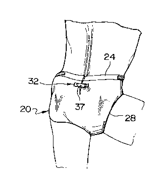
The dlaper 20 of Figures 1 through 4 is provlded in
a basically flat form of somewhat hourglass shape as seen ln
Figure l. The dlaper is of flexlble material and lncludes an
outermost layer 21 of flexlble, llquld-lmpervlous plastlc
materlal such as a polyethylene fllm, an lnternal layer 22
whlch 18 adapted to contact the skln of the user and whlch 18
of a llquld pervlous materlal, and a relatlvely thlck core
layer 23 of ll~uld-absorbent materlal. As seen ln Flgure 1
the dlaper has opposed edges 24, 25 (whlch ln use wlll form
rear and f ront port lons respect lvely of the walst of the
dlaper) and longltudlnal edges 26 whlch are centrally recessed
ln the crotch area 27, the recessed reglons 28 ln use deflnlng
the leg openlngs of the dlaper. Addltlonally the dlaper
lncludes fastenlng means such as adheslve strlps 29 on
opposlte sldes of the rear edge 24 and adapted ln use to be
adhered to the outer layer 21 ln the reglon of the front edge
25 to secure the dlaper ln poslt lon on a user . As descrlbed
thus far, the dlaper 18 of conventlonal form, and may also
lnclude many other features as known ln the art, for example
elastlclzed areas ln the walst or leg openlng reglons etc.
The dlaper 20 lncludes means to counteract leakage
of bodlly waste from the lower back reglon of the wearer when
the dlaper 18 ln use, and to thls end 18 provlded wlth a
pro~ectlon means ln the form of a strlp arrAn~ ?r~t. 32
attached to the outer layer 21 somewhat below the rear edge 24
ln a posltlon where lt overlles part of the core 23 whlch, as
shown in Figure l does not extend as far as the edges of the
dlaper. As 18 most clearly seen ln Flgures Z and 4, the
-- 6 --
60557 -4666
. ~, 2l4~a6~
pro~ectlon means comprises an elongate rectangular strlp of
adheslve coated f lexible plast lc materlal 33 extendlng
generally transversely. Whereas one end portion 34 ls flrmly
secured to the outer layer 21, the L~ ln~l~r of the strlp 33
although coated wlth adheslve, ls not strongly afflxed to the
outer layer 21, but rather ls ~eparated theref rom by a release
surface 36. Thus, although the strip 33 may llghtly adhere to
the release surface 36, it ls readily peelable from the
release surface by means of a flngerllft 35 at lts second end
~as lndlcated by the arrow ln Flgure 2) at the tlme of use.
Before the dlaper has been fitted to the wearer and
secured by the adheslve strlp fasteners 29 ln the use posltlon
as shown ln Flgures 3 and 4, the strlp arrangement 32 can be
actuated to provide the deslred proiection effect by formlng a
pleat 37 . This ls done by f irst peellng the f lnger llft 35 at
the second end of the strlp from the release surface 36 to the
full extent of the latter, then manually formlng the pleat 37
from the materlal of the dlaper lncludlng the core layer 23 80
that ln the central reglon lt is folded over as shown ln
Flgure 4 (and ls thus ln thls localized re~lon greatly
lncreased ln lts effectlve thlckness) and then re-attaching
the end 35 of the strlp 33 to the outer layer 21 of the dlaper
at a locat lon 38 such as to hold the diaper in a width
contracted conflgurat~on 80 that the excess folded over dlaper
material of the pleat 37 remains ln the central splnal area of
the diaper. The adheslve on the lnner slde of the strlp 33 ls
such that, although the strlp can be easlly peeled from the
release surface 36, lt nonetheless wlll form a flrm and secure
bond wlth the materlal of the outer layer 21 when re-attached
-- 7
60557-4666
~ ~60~
thereto as indicated in Flgure 4. Sultable adhesives for this
purpose are well known to those skllled ln the art and need
not be detailed herein.
The st rip 33 may be of any suitable f lexible
material such as plastic film but should of course have
sufficient strength as to resist undesired stretchlng
deormstlon when attached as shown in Flgure 4, since lt is
important to ensure tnat the pleat 37 is maintained. In
Figure 4, the curvature of the spinal reglon of the lower back
area of the user is represented by the chain dotted line 39
and defines a substantial concavlty. By vlrtue of the pleated
arriqn'~ shown however the volume of diaper materlal is
effectively increased, increasing the diaper thickness in this
reglon 80 as to f ill this concavity .
The extent of the concavity is perhaps exaggerated
in Figure 4 and in practice the folded over pleat 37 wlll
usually be somewhat compressed between the spine of the wearer
and the strip 33, and thus wlll be able to expand and contract
to accommodate movement of the body of the wearer, and
malntaln an effective leakage prevention ln thls area. Indeed
the nature of the materlal o~ the dlaper, and in particular
the core layer 23, is ~uch that the materlal of the pleat 37
18 very readily deformed and compressed and ln use may have a
conflguratlon tnat is quite unllke what is seen in Figure 4.
The lmportant polnt is that there is suf~lclent excess of
dlaper material in the central region to provide the desired
proiection effect. It wlll be understood that the concept
illustrated in Figure 1 to 4 can be used to form two or more
pleats in the desired area, or to form pleats at other
-- 8 --
60557 -4666
21~6~
locatlons lf deslred.
The effect of lncreaslng the thlckness of a dlaper
or brlef ln the lower back reglon of the wearer can be
accompllshed ln many dlfferent ways, and an alternatlve
arrangement ls lllustrated ln Flgures 5, 6, 7 and 8. The
dlaper or brlef 40 as seen ln these flgures 18 not lllustrated
ln any detall, and ln constructlon may be generally slmllar to
the dlaper shown ln Flgures 1 to 4. However lt dlffers
therefrom by the lncluslon of a modlfled strlp alL~I~y 42
whlch 18 deslgned to form a double pleat as wlll now be
descrlbed. A strip 43 o~ flexlble but non-stretchlng plastlc
tape materlal has end portions 44 and 45 that are releasa~ly
attached to the outer layer 41 of the dlaper, as through the
use of release surfaces or tapes 46 (see Flgure 6). In the
not ad~usted condltlon shown ln Flgures 5 and 6 the tape strlp
43 18 contalned entirely wlthln the central reglon B of the
flat brlef. At the tlme of use, the ends 44, 45 of the tape
strlp are ln turn peeled from the release surfaces, the
materlal of the brlef 18 gathered and thlckened to produce
correspondlng pleats 47, 48 and the tape ends 44, 45 are re-
attached and adhered to the outer layer 41 ln the approprlate
lateral reglons A thereof. Both ends of the tape strlp 43 may
lnclude a ~lngerllft, as shown at end 45, to facllltate
peellng of the tape ends.
As wlth the prevlously descrlbed ~ , the
- of Flgures 5 to 8 ln use effects a central
pro~ectlon of the material o~ the brief inwardly towards the
8plnal reglon of the body of the user~ As seen ln Flgure 8,
ln the condltlon of use the release surfaces 46 whlch remaln
g _
60557-4666
214~
ln their origlnal positions on the outer layer 41 of the
dlaper now are folded over and lle withln the pleated areas
47, 48
The diaper or brlef 50 schematlcally and partlally
shown ln Flgure 9 ls slmllar to that of Flgures 5 to 8 but has
a somewhat modl~led pleat retalnlng arrangement. It lncludes
a strlp 53 havlng a central part 53a that ls securely fastened
to the outer layer 51, and has end portlons 54, 55 formlng
part of a mechanlcal fastenlng system the coLLe~o~:llng parts
56 of whlch are posltloned at deslred laterally spaced
locatlons on the outer layer 51. As shown, the mechanlcal
fastenlng system ls a hook and loop fastener, the parts 54,
56; 55, 56 of whlch are engaged after foldlng of the dlaper to
form a palr of pleats as descrlbed above ln relatlon to
Flgures 7 and 8. The strlp 53 can be of any sultable flexlble
materlal as described above, or alternately in this or ln the
precedlng embodlments the strlp can be deslgned to have a
predetermined degree of elasticity.
In the ~ r--r1t of Figures 10 to lg the means for
effecting projectlon of the diaper or brief materlal ln the
splnal location comprises a strip of generally stlff semi-
rlgld yet flexlble materlal 62, e.g. of cardboard, plastlc or
metal, flxed to the outslde of the brlef 60 and a strlp 63 one
end 64 of wnlch ls adhesively or otherwise securely fastened
to the outer layer 61 of the brief and the other end 65 of
which can be peeled or removed from the strlp 62 and, after
the latter has been formed lnto an arched or bowed
configuration as seen ln Flgures 12 and 13, can be attached to
the outer layer 61 as shown to malntain the strip 62 and the
-- 10 --
60557 -4666
2~ 4~0~5
assoclated reglon of the brlef ln the bowed conflguratlon by
the bendlng reslstance of the strlp 62 BO that the dlaper or
brlef wlll pro~ect lnwardly lnto the concave reglon at the
splne of the user. As lndlcated ln Flgure 14, the strlp 62 ls
posltloned some dlstance below the walstband area 66 ln a
locatLon where lt overlles the materlal of the absorbent core
67 .
Flgure 15 shows a diaper or brlef 70, whlch may ln
fact correspond to any of tne described embodlments, shown in
partlally formed conflguratlon prlor to completlon of lts
wrapping around the pelvlc region of the user (not shown). It
wlll be seen that the strip arrangement 72 (whlch may
essentially be of any of the descrlbed types) is spaced a
substantlal dlstance below the walst band reglon 68 80 that lt
substantlally completely overlles (and preferably 18
surrounded above and below) by reglons of the absorbent core
71. Thls 18 ln contrast to prlor art brlefs whereln attenpts
to control leakage are essentlally conflned to the walst
reglon 68 where there 18 no absorbent core . Leakage f rom thls
area of the back of the brlef 18 a serlous problem for
bedrldden patlents, and prlor art attempts to allevlate lt
have not been successful.
~et another aLLal~g -~lr for effectlng gatherlng of
the materlal of the absorbent core 18 seen ln Flgures 16 and
17 ln whlch the dlaper or brlef 80 has on the rear part
thereof spaced below the walst band a bunchlng strlp or draw
cord 82.
The draw cord comprlses an elongate f lat f lexlble
bow st rlp 83 whlch lles agalnst the outer layer 81 of the
-- 11 --
60557-4666
~1~6~6~
dlaper or brief and 18 f irmly adhered thereto at dlscrete
spaced locatlons defined by the llnes 84. A pull strlp 85 18
flxed at one end 86 to the correspondlng end of the bow strlp
83, and over the r~~ ln~l.or of lts length lles agalnst the bow
strlp 83, lts opposlte end provldlng a projectlng tab 87 that
extends beyond the bow strlp 83 and 18 manually graspable.
Ad~acent thls tab 87 the pull strlp 85 has an adheslve coated
area 90a whlch ls llghtly adhered to the confrontlng part of
the bow strlp 83, e.g. by the use of a release coatlng or the
llke. As seen ln Flgure 17 the pull strlp 85 18 narrower than
the bow strlp 83, and 18 gulded agalnst the latter by a serles
of spaced flat loops 88 or a further bow strlp (not shown~ the
ends 89 of whlch are attached to the bow strlp 83 at space
apart locatlons above and below the pull strlp 85.
Thus as shown, prlor to use the draw cord 82 lles
flatly against the outer surface 81. At the tlme of use the
tab 87 18 peeled back to free the pull strlp adheslve area 90a
from the bow strlp 83, and the tab 87 18 then pulled strongly
(to the left as seen ln Flgures 16 and 17) to draw the entlre
pull strlp 85 to the left, lncludlng the end 86 that 18 flxed
relatlve to the brlef, and thus to effect a contractlon or
gatherlng resultlng ln a proiectlon outwardly of the
correspondlng part of the brief 80, the effect belng as shown
ln Flgure 18. The draw cord or bunchlng strlp 82 thus acts ln
the manner of a purse strlng to gather the materlal o~ the
brlef at the deslred splnal locatlon. Once the deslred degree
of pro~ect lon has been achleved, the adheslve area 90a of the
pull strlp tab 87 18 pressed lnto flrm adheslve en~
wlth the brlef outer layer 81 to retaln tne draw cord 82 ln
-- 12 --
60557 -4666
! 21~06~
lts contracted conflguration as seen ln Flgure 18. }Iere the
contraction ls ~-- -dhLed by a bowlng of the bow strlp 83,
and produces the deslred projection of the material of the
absorbent core of the brlef 80.
In Figures 19 to 21 the diaper or brlef 90 may l~e of
the same baslc construction as the other embodiments having an
outer layer 91 (typically of thin flexlble polyethylene
materlal) and an absorbent core layer 92, and centrally
arranged on the outer layer a strip arrangement 93 whlch has a
central reglon 94 that 18 flrmly adhered to the outer layer 91
and opposlte end tabs 95, 96 formlng flngerlifts, the
intermediate portlons 97, 98 being lightly adhered to release
surfaces 99, 100 carrled on the outer layer 91. At the tlme
of use the fastenlng strlp 93 18 manlpulated to provlde the
deslred pro~ectlon or bunchlng of the brlef materlal ln the
lower spinal reglon of the brlef as descrlbed before. To thls
end the end tabs 95 and 96 are manlpulated to peel the
assoclated lntermedlate portlons 97 and 98 of the strlp 93
from the ad~acent release surfaces 99 and 100, and the brlef
materlal 18 then folded over at each slde to orm a respectlve
pleat 101, 102 as seen ln Flgure 20. In contrast to the
~ir~ of Flgure 8, ln thlg all~,.n~- L the portlon of the
outer layer to whlch the tape center part 94 18 attached of
course remalns ln contact wlth the latter 80 that there 18 a
separatlon between the lnner folded edges of the pleats 101,
102. The }:rlef core layer 92 18 typlcally of a fluffed up
cellulose pulp materlal and slnce lt ls only llghtly adhered
at intervals to the outer layer 91, lt readlly re-arranges
ltself to a conflguratlon roughly as illustrated ln Flgures 19
-- 13 --
60557 -4666
~ 21~6~5
and 20. It wlll be understood that thls absorbent core layer
materlal 18 very easlly deformable, and can be compressed and
re-shaped readlly to assume the form of tne area ln whlch lt
18 conflned, e.g. the concave splnal area of the wearer. The
essentlal point ln thls and ln the other i ` '1 1.8 18 that
the lnventlon provldes a means for gatherlng a sufflclent
quantlty of the core materlal of the brlef lnto the qeslred
splnal reglon to provlde an adeguate pro~ectlon or increased
thlckness 80 that the splnal concavlty of the user can be
effectlvely fllled and the possiblllty of leakage from the
brlef ln thls area drast lcally reduced .
In Flgures 22 and 23 the dlaper or brlef 110 as
before has a strlp aL~ 113 centrally attached to lts
outer layer lll. In thls case the strlp 113 18 of elastlc
materlal and has one end 114 bonded to the sheet 111 ln a
permanent manner as by the use of adheslves, heat seallng,
mechanlcal fastenlng or the llke, and the opposlte end 115
releasably adhered to the sheet 111, the lntermedlate length
of the strlp 113 lylng ln contact wlth an elongate seml-rlgld
strlp 116 which 18 affixed to the outer layer 111.
To prepare the: ~ur~r-nt of Flgure 22 for use, the
followlng steps are performed:
a) The rlght hand end 115 of the strlp 113 18
detached ~rom the outer layer 111 and peeled away from
the seml-rlgid strlp.
b) The brlef 18 then manlpulated to form the arched
conf lgurat lon as shown ln Flgure 3, thls bendlng
belng ac~ ,deL~ed by the bendlng reslstance of the
strlp 116. c) The elastlc strlp 116 18 tnen
-- 14 --
60557 -4666
214~06~
stretched and lts rlght hand end 115 18 flrmly
secured to the outer layer 111 ln the posltlon shown
ln Flgure 23 to malntaln the relevant area of the
dlaper or brlef ln the arched conflguratlon shown to
form a pro~ectlon thereof lnto the concave splnal
reglon of the wearer.
In use the elastlclty of the strlp 113 wlll r~1nt~1n
the strlp 116 ln the arched conflguratlon and wlll contlnue to
press the arched portlon of the dlaper formed by the strlp 116
lnto the hollow splnal reglon. The strlp 113 may be of any
sultable elastlc.
60557 -4666