Note: Descriptions are shown in the official language in which they were submitted.
~ / +44~ a32-4g05 W I LSCN GUMI`I ~ W 3~g P06 29. 03. g5 11: 2~
~ 1 2 ~ 7 ~
~RANSLATIt)N ~
~P4411526. 1 F~da~
Messrs~ Fedag P 44 Il 526.I : ~;
Hofstrasse 19 -
CH-85~0 l~omanshorn dated 2nd April 19g4
Ys~cuum cleaner ' ,~, ~
. ~''' '' '
rhe i~vention concerns a vacuum clesner according to the preamble to Claim 1.
A vacuum clesner of thi8 ~ind known from ~JS-PS 1 829 582 h~ a dirt collection :::
container which can be in6erted in a hold~n compartment to hold coar$e and fine
particles of dirt. In one suction ~ide there i~ an entry slot for a stream of
su~tion air enterislg the brush cham~er through the ~uction slot. The sl~ction air
stream carries the p~rticles of dirt released by the brush roller into the dirt
eollectiorl container. This latter has a fil~er mat on the air outflow side through
~hich the suction air strealn flo~vs, by which the partic]es of dirt are filtcred out. :
: A~ the entry slot is located in the dust-collecting container above the brush
roller, the suction air stream must lift the particles of dirt correspondingly. The -
heavier dirt particles s1eed a stronger su~tion air stream in order to perform the ; .
necessary liftin~ work. A stronger suction air stream, however, require3, a
correspondingly strong drivs motor, which is very l~eaYy and will impair the
handiness of thc vacuum cleaner
The ~ask underlying the inv~ntion is to develop a v~cuum cleaner of the ~enel~icki~d i~ such a~ manner that, even ~vith a moderate drive performance, heavy dirtparticies can be conveyed with certaintv into the dir~ collection c~ntainer and are
held safely in the dirt collection container.
. . ~ :;
The:task is s~lved ac~ordin~ to the invention by the features of Claim 1. - ;
The suction channel taperin~ at a hei~ht and extending over the width of the ~ ;`;
brush toller aceeierate~ the suction air stream in the direction of the entry 910t, 1 .
as ~ result of which there is~a safe transfer into the dirt collection container of ~ . `
particles of dirt once they have been tr~ppe~ HeAvier particles ~f dir~ t~apped ~:
in the zone of the bru~h r~ller~are accelerated tan~entially to the pe~iphery of ~he ~ ~
rotating t~rllsh roller and hi~ again~t the bottom guide wall, on which they arc .`.
;
~44-161-~332--4905 WILSON GUNI`I IVI'OfJW 399 P07 29.0-3.95 11:29
~ ~a 21~071
~t2AN5L~TION
~ P4~ 11 S26 . 1 Foday ) ~
guidedl be~ause of the oblique position, inta the zone of accelerated f~ow. The
accelerated flow i9 sufficient to carry alon8 heavy particles 4f dirt Iying on the
~ide wall leading obliquely upwards to ~he entry slot, into thi6 ~ntry s]ot. 'rile
guide wall is thus used as a chute for heavy particles of dirt. ~his design
confi~uration ensures the pick up of even hea~y dirt particle9 despite a low andmodera~e drive per~ortnE~nce of the suction fan. The handiness of the vacuurn
cleaner is incre~ ec~use of the low ~Yei~ht it involves.
The ~uctlon channel forms a one-p~rt component with the dirt co]lectio;~l
container, ~o that {f the dust cGllection container i~ taken out Df the holting
comp~rtment, the ~ush roller lies exposed and c~n be ~erviced like this.
~n the outer sleeve area of the suction channel, advantageously a peripheral
receivin~ ~roove i~ constructed for a seal for the airtight scaling of th~ holding
compartn~ont. Strcams of ~ir leaking into the holdin~ compartment which could
lead ~o turbulence and pertormance IOSBeS are thus prevented.
In further develapment of the imention, the dust-collecting container is locatedwith an essential all-rounci distance in the holding comp~rtment. holes being
provided in the walls of the dust-collecting container. 8e~ause of this, a roughly
uniform v~t~um previails in the whole intermediate space between dirc collectiorl
cont~iner and holding compartn~ent, so that the suction Gir strearn en~ering thetirt collection container passes uniformly throu~h all Ihe holes located in the wall
of the dirt collecti~n container. ~s the hole~ are located at least over the largest
part of the dirt collection container, iI is ensured that no preferred direction of
flow arises from the s~ction side to the outlet side which would ~avour an
ob~truction of the outlet side~
. ~ ~
In order to a~hieve a ~ood handiness and mobili~y, it i~ provided that, seen in the
direction of operation, behin~i the brush chamber in the botlom sectiorl, holdin~
domes for runnin~, rollers are loc~ted, which can be swung especially about
vertieal axis. These running rollers are provided in addition to run~in~ whcels
located in thei re~r zone of the bottom section and ensure a dist~nce which can be
~djusted in le~el between the underside of the bottom ~ection and the floor. ~n
the ~one of che suction slot therefor~, the entry of the suction air c~n be
influenced in order to m~ke pos~ible an optimal pick up of particles of dirt
. ,.~.-
; ''":,'
~44-161--832--4905 WILSON l~iUl`D`I ~1'CRW 3g9 P08 29.03.35 ll:Z9 ' ~:
2 1 ~ 6 0 7 ~
n~: T~NSLA~ION
( P4~11526 .1 ~dag ~
The vacuum cleaner has a pivoted handle column. the swing axis of which may
- coincide with the axis of rotation of the drive motor, ~hc handle column can ~e
swung between a vertical position (standing pogition) and a horizontal posit;on, ; :i
whicb can be used, for example, for going under low pieces of furniture. For
ergonamically favourable handling of the vacuum cleaner, the handle colwnn c~n :, ~
locked in a working position ot' ab~ut 4S~. n.
:,;, ~:
In order to prevent with certainty th~ vacuum cleaner from ti~pin~ up, both whenin its rest position aJ~d in lts vorking position, it is provided that Ihe rotation
axis of tho drive motor in a workin~ direction is in front of the axis of rotation ~:
of the rear r~nrlin~ wheela which carry the main weight of the vacuum cleaner.
In thi~ manner, the person usin~ it is campletely relieved of the wei~ht of the
Yacuurn clean~r.
On the handle column, a fine dirt box with a fine dirt container, located after the s ~.
dirt collection container, can be arranged. The suction air stre~m coming out ofthe holding compart~nent is ~ubjected in this case to re-cle~ning for filterin~ out - ~.
fine partic1es of dirt. Puring this, the suction air stream can ~oe led throu~h ehe :~
internal space of the h~ndle col~lmn, the, handle column being removably pushed "-
into a hos~ for connection to the holding compar~Tnent. lf the handl~ columin issep~rated from the hose, dirt can be suckcd o~t from upholstery and from
corners by the free end of the handle column as a suction nozzle. The other end
of th~ handle columD debouches expediently into a hose which is connected to thefine dirt conti~iner. `~
Anothe~ dust filter with a ~ilter area of preferAbly about l ~n~ can be located on ~.
tho discharge side og the fine dust container~ by which it is possi~le to filter out ::~
the fine~t tu~t and bacteria ~rom the su~tion air streanl, so that the ~ncuum
cleal~er cn al~o be used in cle~n rooms. ; -
Qther fe~ture~ of the inventlon emerge from the desc~ipti4n and drawinss, in ,; .
which practic~l ex3mples of the invention descri~ed individually below are
lllu~trat~
' ' ' ".,
Fi~. 1 shows ~ perspec~ive view of the vacwm cleaner accordin~ to t.he ;~
invention, with an open s~ction of the holdin~ compartmenc, ~:~
~ ' .'. ' '
,:
+44-161-a32-4905 WILSOII EiUNt~ ~1'ChW 399 P0g 2g.03.95 11 ~9
r~~4 2 1 ~ 7 1
TRAMSI.A~ION
~P4411526. ï Fed~g)
Fig. ~ shows a top view onto th~ bottom shell with holding compartment in the
bottom section,
Fi~. 3 shows a side view of the bottom shell,
Fig. 4 shows a enction throu~h the dirt collection containar,
ig. ~ shows a slde view onto the dirt colle~tion contain~r,
Fig, 6 shows a rear view onto the dirt collection contain~r, .-
Fig. 7 shows a top view onto the dirt coll~t;on container,
Fig, 8 shows a s~de view of bottom shelJ and insert~d dirt colleotion container
including brush ro~ler and runnin~ rollnræ, ~::
.:
Fig. 9 shows a front view of the co~er, :: .
Fig. 10 shows ~ rear vi~w of ~h~ cover,
Fig. Il show~ ~ sMe view of the cover, ~:~
Fi~. t2 show~ a perspective view of the vacuurn cleaner in the fo~m of
embodiment with fine dust box, ~ ~:
Fig. 13 shows a perspective view of the vacuum cleaner accordin~ to Fi~. 12'in ~ n~
thc stretched out position, : ~,
Fig. 14 9hows a perspective view of a ~acuum cleaner with fine dirt box and an
electric motor ~s9igne~ to the brush roller, ..
~ig. 15 shows a top view onto a cover cap of the drive motor,
,;: ""~,.,
Fig. 16 shows a side view in seetion through the finc dirt ~ox, -~,",~ .
Fi~. 17 show5 a front ~ie~v in section throu~h thc fine dirt box,
. ~ ' . ! . .
. ,., ~ ~,, .
+44-161-832-4905 WILSO'.`I GUNN l'I'C:f:lW 399 P1029.03.95 11:30
~ ~2 1 ~ 6 0 7 ~
TRANSLAT I ON : .
( P4 4 1 1 52 ~ .1 Fed~
Fig. 18 shows a top view onto the fine dirt bo~,
, .
Fig. 19 shows a rear view of a lower section located in the fine dirt box.
Fig. 20 shows a cut-out front view of the lower section, ::
Fi,~. ~1 shows a top view of the lower section,
Fig. 22 shows. a rear view of a baffle plate engaging with the bottoln s.ection,
Fig. 23 shows a cut-out front view rf the baffle plate, -
Fig. 24 shows a top vie~w onto the baffle plate, .
Fig. 25 ~,hows a perspective partial view of the vacuu~n cleaner with a dlscharge
turbine and drive belts, i i~
~, ...
Fiy. 26 ~hows a r.ers~ective view of ~ suction nozzle without drive motor. .
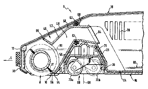
The vacuum cleaner 1 i~ustrated in a perspective view in Fig. 1 conslsts basic~ily -~
of a bottom section 6 which has a bottom ~hell 16 as a carrying con~pon~nt. The
bottom she]l 1.6 contains, in its central zone, a holdin~, compa~tmel~ 14 op.cn aE
tllo top, Fi8s~ 2 and 3. ~n t'ne front ~one of the '.-.ottom shell 16, seen in a : ;.
working direction 5, a suction slot 10 open~n~, downwards has '~ew let in, o~er
which a cylindrical brush roller 8 extenàs, which is jo;ned to a drive ~nit 82
through ~drive belts 80 and is displaced in a rotatic.n moYement. A brus.i 11 isloeated on the 91eeve surface of the brush roller, which r.~ches to the fi~or ~:
through the suction slot IO and, hecause of the ~otation mo~enent of the brush
roller 87 picks up co~rse and fine ~articles of dirt fro~n the Floor being cle~n~.
A ~uction air s~reasn produced by a 31lction fan 12 whi.~h i8 o,pe~ated ~y a drivc ~ :
.motor ~. takes up the F,~rticles c.f dirt picked up fro.n the floor and s~cks Ehem
into the bottorn scction in the direction of a holdin~, compartJrent 14, from where
tHe suction~a.r stream is led out through a dischar~,o`channel 21 antl is 6ubjectgd
to re-filtering in further progressic.n or is discharged into the atmosphere. ::
In .~he holding com,.artment 14, in accordance with the inventjon A dirt collection
container 24 is inserted which is preferably made of plastics and .has '`
': "'.,
' .::
+44-161-8~2-491a5 WILSOI`~ GUNM l~'C~W 3g9 Pll c9.E~3.gS 11:30
21~607:~
TF~AN8LAT I ON
(P4411526. 1 Feday)
appro~imately 4 li~res capacity, and the wall 26 of which i~ provided with hole~or recesses 2$ which, according to ~ig. 1, ha~e a circular sh~pe in cros9-section,
bu~ can in principle have any ~hape whats~ever, such as, for example, a
rectangular shape, ~nd may be dlstributed both regular1y and irregularly over the
wa3126, see Fig. 7. Oll the external s;des of the dirt collection container 24
th~re are distanein~ pieces 44, Fig. 6, so that the external sides 30 of the dirt
collection contaixler 24 are at a distance frotn the holding compsrttnent Z4. The
di~tan~itl~ pieces 44 can have the shape of di~rancin~ knobs or, accordin~ to a
pr~ct~cal example not illu6trated here. are constr~cted ~s moulded bevels in theshapc of ~ w~li locat~i ~t ~n an~le to the wall of the holder ~ompartment of thetirt collection container. By thi~, accordin~ to Fi~. 6, an intermediate space
~etween the holder compartment 14 ~nd the dir t collection container 24 i.
defined, the width b of which is dctermined by the hei~ht of the distancing knubs.
This intermediate space situated betwe~n the suction side 20 facin~ the 611c~ionslot I0 flnd the dischar~s side 22 of the holdcr compartment 14 facing the 8UCtion
fan 12 is ~lbiect to a Yacuum b~cau~e of the suction aif fiowing thlough it, so
that the suction air which has entered the dirt collection container 24 pas~e~
throu~h the pe~foration of the d3rt collectiGn container alld is led sway out of the
holder compartment 14 ovcr thc dischar~e side ~2. The dirt collection container
h~ a concaY~ sec~ion 27 Dn the disch~l~ge side 22 in the zone of the o;~ening ofthe oue~oin~ air channe] 2t, through ~hich there is a slightly larger di~tQnce
between external w~]l of the dirt collection container and the raouth aperture of
the outgoinp air ch~nnel than there is in the other zone of thc intennediate
space. This fa~ours the propa~ation ~f the Yacuum in the whole intermediate
8p~ce. No preferred direction of nOw from che suction side 20 dire~tly tO the
outgoing alr side 22 arise3, since a more or less uniform Yacuum pr~vail~
everywhere 3n ~he intermediate sp~ce betwcen the dirt collection cont~iner and the
holder comp~tment, 90 that the suction air can flow a~aY more or less uniforml~
distri~uted through ~l] the holes in the walls of the dirt collcction container. It
is thus ensured that the suction air doe~ not flo~ in preference either ~hrou~h the
out~oin~ air side or any other wall of ~he dirt collection container, which would
favour obstruction of; ~he perforation by coarse an~ conglomerated parttcles of
dirt. Because of the ~niform exit of the strearn of suction air throu8h all the
holes rnade in the wall of the dirt collcction container 24, a one-sided deposition
of dirt on one 3ids of the wall is certainly prev~nted, so tha~ uniform filling of
he dirt collectirn container with particles of dirt of different si~ea i~ en~ured.
, ',".;
~; :
. - . .
+44-161-E332 4905 WILSONGU~N rl~CRW 399 P1229. 03. ~5 11:30
~ ~ ~2~60~ ~
TR~N~LA~I0
( P44115~6 .1 Fedag ~
~:,' ',,
~t may be expedient to construct one side of the dirt collection container 24,
especi~ the front limiting wall, located on the suction side 20, so that it i8
closed - withollt perforations - and to have this slde ]ie dir~ctly o~ th~ ~ottom
shelt l6, 90 that at this point no intermediate space is formed between the dirtcollection eontairler and the holding compartment. Because of this, a pressure
drop ori6es irl the Intermedi~te space, with rising vacuum in the direction o~ the
out~oing air channel 211 which fa~ours ~ accelerated and tar~eted ~traction of
the suction air ~tr~m from the interm~diate space.
As ~hown in Fig. 11 ~ filter 32 can be inserted into the d;rt collection containel
Z4 ~vhich ~l~o filters fine particles of dirt out of the suction air ~tream The
filter 3~ has on its front side facin~ the brush roller 8 a slot 33 through which
~he suction air ~tréarn enters the filter, and which advantageously ha~ thc sarne
crc,s~-~ection design a~ ~ debouchment slot 64 fitted in the dirt collection
cont~iner 24 on the sucrion side 20, see ~igs. 4 ~nd 8. ~he debouchment slot
~ extends expediently over the whole len~th of the brush roller 8 and forms the
debouchmant opcni~g of a suction channel 48 between brush roller B ard holding
comparunent 14, which is folmed by an air ~idance section 46. In a
preferreci for~n of embodiment, the air guidance section 46 is jc,ined in one piece
with ihe dlrt collection container 24, a lo~r guide wall S0 and a top al~ide wall
52 accordin~ to ~i~. 4 delimit the suction channel 48, which tapers towards the
holding ~ompartment 14 in the wne of the air ~uidance section facin~ the bnlsh
roller 8 and en~ures a defined inflow direction or the suction Air stream from the
floor tow~rds the holding compartment. The front, free end 53 of the air
guidRnce section fæin~, the brush roller can here'e~pediently partially enclose the
brush roller 8 radially? F~g. 4, wi~h the lower guide wall 50 an~ the top guide
wall S2 of she air ~uidance sec~ion 46 enclosin~ the bru~h roller ~ preferably over
an ~ngle of approximately 90~ The free end 55 of the top ~uidance wall 52
may, according to Fig. 4, lie concentric with the sleeve surface of the bru~h
roller ~ 8, or, ag lllustrated in Fi~ 8, be constructed in a different form of
em~odiment as a straight end piece which is alig,ned approximately tangentially to
the sleeve surface of the brush roller.
'1: . ' i I : ,' ~
The free ends of ~he air g.uidance seetion 46 enclose ~he brush ro~ler 8 preferably
over their enti~e length, so ~hat even the particles of dlrt picked up fram the
floor at the axi31 face sid~s of the br~lsh roller are con~eyed with certainty
through the sllction channel 4~ to the dirt collection container 24, and turbulellces
+44~ 332-'~905 WILSO~ GLINI`I rl'CflW 3gg P13 29.03.95 11:31
~ 21~6071
lL'RP.N~3L~ ~ON `:
(P441lg~6. 1 Fe~ag) , :
in the suction air stream and deposits of dirt cbused by this in cornerY, ed8es and
niches are avnided with csrtainty.
A bottom lip 5.1 i9 formed by the free end of the lower guide wall 50 of the airguid~ce seetion, said lip ending just a~ove the floor and bein~ delimitcd by therear side of the suclion slot 10 se~n in the working direction 5. Th~ fron~ limit .:
of the suction 910t 10 iS form~d by a front wall 39 of the bottom shell 16, Fig. Z.
It has proved expedient here to construct a 8reater air gap between the front wall
3~ of the bottom shell 16 and the floor than between the bottom lip 5~ and the . :~.
floor, by whi~h it is ensured th~t even lnrgish items of dirt, ~uch as for example ; ~;
ci~rette stubs, can Ret into the ~one of the suction slot 10 without being pushed ~:
WAy by th~ front wall 39. At the rear delimiting wall of the suction slot 10
formed by the bottom lip 54, aaainst this, particles of dirt are preven~ed from :
slippin~ throu~h under the vacuurn sleaner by the bottor,1 lip which reAches
dccper down and are raised ~y an oblique position of the lower gllidance wall SOof the air ~uidance section 46 in the direction of the suction channel 48. ::
. ~.- ,. ;.
~ecause of the sin~le-piecc construction of the air guidance section 46 and the ; ~ '
dirt colleetiori container 24, when t~king the dirt collection cobtainer out of the :i :- .
holding compartment 14, ~t the sarne time the top zone of thé brush roller 8 is
al~o exposed, which can then, for example, be freed of dirt ~ihering tQ the brl-sh
11. In a form of embodi~ent not illustrated here, the dirt col]ection CDntainer ;. . `
~4 and the air ~uidance section 46 can also be constructed in two partsl 5~ that . ~s:~
for emptying, only the dirt collection contahler Z4 can be taken out o~ the holding
aompartment 14, without the air guidance section 46 also having to be takerr out ~ r . .
wilh it. It may also be expedient to join only the top ~uklance w~ll S2 of the air - `;
guidance section 45 detachably to the dirt collection container 24 in order to .:
create a top ac¢es9 tO the brush roller 8 indep~ndently f~om the dirt collectioncontairler 24. .
A cover 18 is placed onto the bottom shell 1~ which covers over the brush rollerand the holding comp~rtment Accordi~g to ~igs. 9, IQ and 11 the cover 18 :`;consistslof a top~ side limiting w~lls and a front side l~, which par~ially covers `;.
over the front side of t~e brush rollar 8. Ac~ol~ding to Fig. Io, the cover 18
ha~ latch e~tensions 2~ which can be loek~ into recesses ~not ill~l~tr~ted) on the
top ed&e of ~he limiting wall 31 of the holding co~partment 14 situated on ~he
utgoing air side 2~. On thc oppQ5ite front side 1~, latch rcccsses 35 are fitted
+44-161-133~-4g~5 WlL~;Oli GU~ 'Cf~W 399 P14 2g.1~1~.9S 11:31
~SLAT~ON 21~ 6 0 7 ~
~P44115~!6.1 Fed~g) ' '
~:,., ':.'
like~se, in which the latch extensions 37 of the frDnt wall 39 belon~,ing to the ~'
bottom shell J6 engage, ~ee Fig. 2. In the case of the air guidanc~ secsion and
dirt collection containers being made in two pieces, it ma~r here be advantageous
to construct the lid 18 also in two piecesl so that the dirt collection container or . '
the air guidance ~ection c~n be taken out separately.
On the ext~rn.i3 sleeve surface 58 of the air ~uidance section 46, a surroundin~groove 60 is pr~ferably fitted, Figs. 4 and 5, into which a scal 62 can be ' '
insertet3, Fig. 8. Thc seal 6~ seals the holdin~, compartment 14 airti~ht in
relation to the tottom sheli 16 AS well as the side limitin~, walls and the top of thc
cover 18, in order to prevent fa~lty air streams between the air ~uidance sect;¢n
and the 2tmosphere, which cou~d lead to turbulence of the suction air streQm andreductions in per~ormance. ;~
~ , :
As can ~e taken from Fi~. 8, in the bottom shell 16 a more or ]e6s tr~pezoidal
reces~ 76 is advanta~,eougly moulded in between brush roller and holdin~
~ompartment, in which runnin~ rollers 66 are Iscated, e3pecially ~,uide rollars 7~
which can be ~wung, about a ,rertical axis 68~ which ensure great mobility of the
vacuum cleaner 1. The ~uide rollers 70 can be swung about their vertical axis
68 without o~struction because of th~ trape~c~idal re¢ess 76 which broadens
downwards, æe positions 70~ and 70b in ~ig. ~. ln order to be able to insert
the dirt collection container 24 and the air guidance section 46 positively into the
bottom shell 16, the recess 76, in accordan¢e with ~i~s. 4 and S, is also formed'oy the bottom ~uide wall 50 of the air guid~Lncc section 46, or a front li~lit wall
, 25 of the dirt collection conteiner 24. The ~uide rollers are fixed adjust~b3y in
hei~ht on an eccentrical1y s~pported shaft 72, the shaft axis 74 of ~hich extend3
transversely to the workin~, tirection 5 throu~h the trapezoidal recess 76, see
Fig. ~. The hei~ht adjustment of the guide rollers'can also be carried out with
th~ cover l8 closed from outside, ~or which ~ more or les~ ~emicircular reces~ 77
is fitted on a side llmit wail of the cover 18, see Fig. 11. It is expedient to
provide sevèral iocking positions for the hei8ht adjustmcnt of the running wheels,
in order to make po~sible easy transfer frorn one locking position to the next
i ~ I one. Because of the adju~ment in heigh~ of the running rollers, the distance
~etween the underside of the brush roller 8 or of the suction slot 10 to the floo~
EO b~ cleaned i~ fl)~ed; thi~ distance can be n~Qtched to the particular floor
condition or the kind of the dirt to ~e picked up (coarse dirt. fine dirt).
" ' :
~'14-161-83~-4905 WILSOI`IGtJN~I M'CflW 399 P15 2~. 03. ~5 11:31
~IV
~r~ANS~'rION 2 ~ 4 6 0 7 ~ :
~P4411526. 1 Fed~g)
."
:: :,~ . ..
In order to make possible the maximun~ width o~ s~ction, tho brus~ roller 8 ''~
extends expediently over the entire width of thc bottom section 6 or of the dirt :
collection containeir 24. In order to incrcaso the suotion width~ the brush roiler , , -.-
8 can also have a ~re~ter Icngth than the width of the dir~ collection container 24 . .
and protrude by one of its front sides 78 or 78' at least on one side beyond the '
dirt collection cont~iner, see Fi~. 13 and l4. tn this case, to enclose thç ''
bottom roller and to construct the ~uction slot 10, even the bottom section itselg, ' ~ :::,
the air ,~uidance section 46 and also the cover IB are matcheci to the protrudin~ : ,` '"
len~th of the brush roller. ' ,' ':.,
~t is provided for the ~rush roller 8 to be dri~en throllgh drive belts 80 from a ~ ~:
drive unit 82, it being possible for the drivc unit 82 accordin~ to J~i~. 1 to be a '.',: ' ,,
turbiDc 15, which is driven by the suction air stream comin~ out of the holding . :` '~ ', '
co~npartm~nt 14. The turbine 15 is supporte~ 60 that it cannat be rotated on a '~
s? aft 17, the free cnd of which is wound round by the drive belt 80. The ,~
rotation axis of turbine 15 ~ind shaft 17 is preferably identical to the ~otation a~cis ,"', ',' ;
34 of the drive motor 3. According to Fig. 14, the drive unit 82 can al$o be a i', " '.:
separate electric drive motor 86 which is located in addition to the drive motor 3 ~ -''`'!j'~-''
of the suction fan 1~. It is al90 poss;ble to use the drive motor 3 as a drive
unit, the hi~h rota7ion speed of th~ drive motor bein~ reduced to the rotation
speed of the brush roller through a gear reduction. -'''-'
After flowing through the dirt eollection container 24 ~he suc~ion air st~eam '',.
eaYes the:holding compartment 14 throu~h an out~oin~ air channel 21 located on . ;~
the Qu~oing air ~ide 22 of the holding compartnlent and is led to the suction fan ~ .,,',.,.,-",
~2. In the embodiment ac¢ordin~ to ~ig. 1 the saction air stream is now finally
filtered and, on the outgoing air side of the suction fan 12 leaves the vacuu~
cleaner throu~h blow-out apertures 42 ~vhich are located in the bottom shell 16 ~ -
according to Fig. 2 and may have a rectan~ular shape of cross-section. After
this~ the air stream is brou~ht to leave the ~ac~um cleaner to the floor and is
directed into the carpet, becausc of which there is a noise-dampin~ ef~ect.
"~
In the rear,~one 88 of the ~ottom section 6 a pivoted handle column 2 wi~h a i ~,';~'.".,`~,
halld~rip 4 is located, which is llsed to guide the vacuum cleaner. In a prefe~red ,."
elnbodiment, the pivot axis Or the handle column 2 coincidcs with the rotation
axis 34 of the drive motor 3. ~he handle column 2 can ~e swun~ between a -'. '~
vertical posilion as illustrated for example in Fig. I and a hori~ontal posi~ion,
+44--151-832--4905 WILSON GIJ~IN M'C~W 399 P16 2~.03.~5 11:3~
~1~ 21~607~
ANSL~TION
~P4~11526.1 Fedag)
Fig. 13, by about 90, th~ vertical position being the upright position 89 of thBcleP~er and the hori~ont~l position eapable of bein~ set, f4r example$ to be able to
move under low picces of furniture or to be able to store the machine in narrow
stDra~e compartments. ~or the ergonomic guidance of the vacuum cleaner, the
handle column 2 can be locked into a workin~ position g2 whlch is preferably
a~out 45-, see Fig. 13. In order to be ab]e to guide the cleaner for several
houl~s ~ithout signs of exhaustion, it ~n be i~dicated that other lockable working
positions may be provided. ~n addition, the handl~ col~lmn 2 can be pulled out
~elescopically in its axial direction ~1, 50 that the vacuum cleaner ~an also beoperated without exhaustion ~ person~ o~ different height3. A height-adjllstablehandle column of this kind ~an also be provided in the practical example accordin~
to Fig. I.
,:
Similarly, in the rear zone 88 of the bottom shell ~6 there are running wheels 7which bear the m~in wei8ht of the vacuum cleaner. In order to rule out the
p~sibility of the vacuum cleaner tipping bac~wards, the axis of rot~tion 9 of ~he
running wheels 7 seen in the working direction ~ lies preferably bchind ths axisof rot~tion of the drive motor 3. The n~ain weight of the vacuum cleanor thus
li~s in front of the axis of rotation 9 of the runnlng wheel~, so that asl erect;n~
tor4ue acting nround the axis ~f ro~ation 9 keeps the vacuum cleaner in an
upri~ht positions. A~ the handle column 2 can pi~ot about the axis of rotation
34 of the dri~Je mstor 3~ it is thus en~ured that both in the standing position and
in the workin~ posltion of the handle co1umn ~, ~he wei~,ht of the vacuum cle~ner
is cArried in eYery case by the runnin~ wheels 7 and the ~nnin~ rollers ~6. The
cleaner c~nnot f~ll over; the operator is thus completely relieved of the weight of
the machine,
:
~n the embodiment startin~ from Fi~. ~2 it j9 provided that, for re-filtering ofthe suctlon air s~ream coming out of the holding compartment 14, a fine dirt box94 ;9 arranged in which a fine dirt container 96 is fitted for filt~ring the fine dirt,
see Figs. 14 and 16 to 18, The suction air strearn coming out of the holdin~
sompartment 14 may stili contain fis~e particles of dirt and dust which are filtere~
out in the fine dirt ~ox 94.
'
The suction ~ir stre~m leaves the holding compartment 14 through an outgoing
air chsnnd] ~1 into which a hose ~02 debouches, which is ied through the fine dirt
box ~4, Fig. ~4. The hose 102 opens a~ its end facing away from the holding
+44-161--a3Z--49~5 I~IILSO~J GUNN r1lulw 399 P17 2g.03.g5 11:3~
2 1 ~ 6 0 7 ~
TRA~;LA~It)N
(P4411$:26. 1 Fedag) -:: ,.-.
compartn~ent in the botto~ end piece Y~ of the handle column 2, the intelior of
whlch is preferably ~sed as an air-carfyin~ component. The bottom end piece ~ :
98 of the handle column 2 is ioined, advantageously so that it can be cietached, to '.
the hosc 102, for exa~pls in the form of a plug connection, in order to separ~tethe h~dle colurnn ~rom the hose 102 and to be able to use the then free end 9~ ;
of the handle colu~nn as a 3uction 1o2~1e, for ex~s~ple, to be able to suck dirt : -:
from corners with difficult access or ~rom upholstery. ln addition, residues of
dirt and dust which, after removhg the dirt collection c~ntainer 24 laden with
coarse dlrt are situated in the ho~din~ cornpal tment 14 are easily extracted and :~
cleaned with the aid of the suction nozzle formed in this way.
The oth~r enti 103 of the ~ndle colurnn 2 ~urneci away from the dirt collection
box 94 is similarly expediently connccte~ tO a fiexible hose 104 which i3 led into :~
the fine dlr~ container located in the fine dust box 94. It has proved to be
expedient he~e ai30 to use the handgrip 4 as an ~ir-carryin~ component betweer~ "
handle colurnn ~ and hose I04.
,: :, ;,"~,,
The hoses 102 and 104 are advant~geously constructed as stretch-hose3, which
has the ~dva~ta~ge, especially with a detach!ed handle colllmn 2, th~t the workin~
radius of the handle column used as a suction no~le carl be incre~ed by
stretchin~ of ¢he hose 104, preferably to a rQdi~s of over 2.5 tT.
For a type oF construction which sa~e~ the greate3t possible $paee, iL may be
sensible to fit a rnotor cap llO accordin~ to Fig. IS with a more or less
rectan~ular recess 1~ rounded off at one end approximately in the shape of an
arc, which coYers the drive unit ~2 and the suction plan 12, into which the hosepiece 102 comin~ fro~n the holdin~ compartment is inserted. When ~he h~ndle ~
i9 pivoted from the vertical rest position int~ the horizont~l stretched position
al~d ~ack ~gain, the hose I02, especially if it is constructed as a stretch hose~
perf~rm~ a stron~, stretchin~ moYement or contraction, the external hose
diarneter also chan~ing. The open guidance of the hose 102 through the recess
î ~2 of ehe motor cap 110 does nc,t obstruct these contract;on and stret~ch
movements in any way.
The hose 104 led ba~k into the fine dir~ ~ox ~6 debouches into a pipe IOS ~hich
projeet~ throu~h a removable cover 9~ of the fine dirt box g4 into the fine dirtcontainer ~fi. ~ fine dirt fil~er 97 i9 advant~geou~ly inserted in the fine dirt
.....
~ ....
+44~ a32--'~9E15 I,IILSONGUNl`i l`~UCflW 399 P1E3 29. ~3. 95 11:3~
f~ ~13214607~
. . . ,,, ~ . .
:'- TRANSLAT I ON
~P44tlS2~.1 FeClag~ !
container 96, it bein~ possi~le to introduce said filter when the cover 95 i9
removed from the t~p l`he filter holds back the fine particles of dirt and dust.~he flne diri filter 97 i9 expedien~ly ~ double-layer paper filter bag with a
capacity of ab~ut 5 litres. As can be taken f~om Fig. 16, a dl~st filcer 108 can~e locateai aft~r the fine dirt container 96, which holds back the fines~ dl~s~ ~nd
bacteria and preferibly has a filter surface of about 1 m2. ~he vacuum cl~ancr
can thus also be used for cleaning clean rooms, for example production shops forrnicrochips.
The suction air stream 13 flows throu~h the filter 97 in the fine dirt container 96
and pa951~5 through passage aperturej 107 which are located on the outgoing air
side 106 of the fine dirt container 9~, into the du~¢ filter 108. The cover 9S ca~
be divided into two in order to be able to take the filter 97 and the dust ~llter
108 from the ~ine dirt bax 94 independently of each other. After Mowing
through th¢ dust filter 108 the sucti~n ~ir stream 13 is led into an ou~oing airchannel 109, which the suetion air stream 12ave5 downwards through a pipe 1~3
projectinS into the out~oing air channel 109. The pipe 113 is ¢on~tructed in onepiece with a ~ottoTn part 114 which dellmits the undcrside of the fine dirt bo1~ 94,
see Fig. 19 to 21. A reverging part 116 is flan~ed onto the underside of the
b~ttom section ll47 see Fi~s. 22 to 24. The bottom section 114 and the
reve~sin~ part 116 jointly form an air ~uicance 113 into which the pipe 313
coming from the top debouches and the cross-sectional sh~pe of which, in a top
vicw accordin~s to Figs. 1~ or Fig. ~4, has a form running at ri~ht angles and
tape~in~s. The sucti~n air stream 13 coming from the pipe 113 is led throu~h theair ~uidance llS Yhich runs rrore s?r less parallel to the ~over ~. The air
guldanc~ 115 runnin~ at ri~ht angle6 is led around a throu8h-pass hole ll8 whichi8 led with a bottom section 114 and reversin~ s~ction 11~ piac~d on top af each~ther through the two connponents ag a continuous hole. The ho~e 102 comin~
fram the out~oiny, ~qir channel 21 is led upwarcis to the bo~tom end piece 98 o~the handle column ~ through the passage hole llB, see Fig. 17.
The ai~ gui~iance 115 debouche~ into a pipe 117 runnin~ downwards and belonging
to the reversing section 116, through which the suction air strcam 13 again
leaves the fine dirt box ~4. After this, the su~tion air stream 13 is eithei led to
the su~tion f~n l~ h~d then through blow-out aper~ures 42 in the bottom shell 16into ~he atmosphere. The air s~ream can, ho~e~er, also first ~e le~ to a turbine84 which drives the brush roller ~, see Fi~. 2S. After rlowinj~ throu~h che
~"'; '
''':
..... .. - -
+44--161-~3~32--49E15 WILSON GUNIS I~I'CRW 3~S~ Pl9 29.03.g5 11:33
^ -~ ~'" 2~46~71 -:~
:: TRANS~ I o~ , : :
(P4411526.1 FQ.day) : ~ -
turbine ~4, the air stream is again led to the suction fan 12, from where it leavGs : ~ ~
the vacuum cleaner in the direction of the foor through the blow-out apertures .-,
42 ;~
'"";"~" :"''
~n the fron~ zon~ of the fine dirt box 94 a holding eomp~rtment lû1, see Figs. l4
and Fig. 1~, exten~s over the entire hei~ht of the fine dirt boxl which runs ~ ;f ~,
par~lld to the dust filter 108 and through ~1vhich the hose 10~ is led upwards to
the handle column 2 This holdin~ compartment lOI provide~ enou~h stolaRe
~pace to hold, in addition to the hose lO~, also small tools and acces60ries such
a8 clip-on nozzles and replacement filters. ~he holdin~ compartment 10l can be ~-
opened throu~h a removable front section 103 of tho fine dirt box, by which ~t :.: :.
the same time th~ hose 102 i$ rnade acce8sible for service worlc.
: : ,
Another practical cxample is illustra~ed in ~i~. 26. The bot~om section 6 is
constr~lcted as a suction no~zle 120 which does not h~ve its own drive mstor for : ~
~ suetion fan7 but can be in3erted as an additional part ror norrnal vacuum . .`.'.
clean~s. The ~uction nozzle consists cssentially of the brush roller 8 driven byt~e brush motor 86, the holding component 14 and also the dirt collection ~.. ;
~ont~iner 24 fitted with perforations 28. The out~oing air channe~ 21, tbrough
which the suction ~ir flow~ from the holding compartment 14, debouches into a
suction pipe 122, Into which a handle column 2 c~n be inserted. The holding : '`
compartment 14 altd the zone above the brush roller ~ are sealed by a two-par~ ' .
cover 18j 18', it being possible for the part-~overs co be openeù independently . :.:
from each other by cpenin~ catches 23, Z3'. As the 6uction nozzle 120 itself
contains no drive motor and no ~uction fan, the suction nozzle is expediontl~
suited ag an accessory for convention~l floor vacuum cleaner~ which h~ve their ;~
~wn drive motors. ~ . ;.
It is expedient for aJl the entry end passage apertures throu~h which the suction .
air flows, such as for example the sucti4n slot lO, the perforations 28 in the dirt .
collection cont~iner ~4, the blow-out apertures 42 etc to ~e of a t~pe with ~ `
rounded-off cornors and cdges, in order to prevent the particles of dirt carried . .
aldn~ in the suction air stream from obstructing the ~pertures. ` ."
,~
-'