Note: Descriptions are shown in the official language in which they were submitted.
2 ~ 4 6 1 2 4 pcr/cA93/oo4l3
W094/07629
METHOD AND APPARATUS FOR PRODUCING METAL STRIP
BAC~GRO~ND OF ~E l~v~ ON
This invention relates to a method and apparatus for
the casting of molten metals as continuous strip and, more
particularly, to the casting of lead and wide-freezing range
lead alloys as continous strip for use as electrode grids for
~atteries.
For many year~, the manufa~luLers of lead-acid
batteries have used a variety of lead alloys in the
preparation of grids. The casting methods for these alloys
include ~ook mold casting, casting into a sla~ followed by
rolling to form a wrought product in the form of a strip, belt
casting, twin-belt casting, double-drum casting, and casting
onto a drum rotating in a bath of molten alloy, the so-called
"melt extraction solidification" or "dip-castin~" method. The
last-mentioned method allows the manufacture of alloy strip
directly from molten alloy.
S~ s~sful dip-casting involves the providing of a
smooth flow of dro~s-free molten metal to a 20ne through which
the circumfersnce of a chilled casting drum rotates. It is
necessary to extract heat at a uniform rate across the width
of the strip to produce a uniform thiC~cs of the strip
across the drum. The dip-casting method is suitable for
casting pure lead and for casting lead alloys which possess ~
narrow freezing range, such as lead-calcium or lead-calcium-
tin alloys. For the manufacture of battery grids from cast
strip, the lead alloy strip i5 expanded and shaped to form the
mesh used for battery grids. Other methods used for producing
grids have included the direct casting of alloy in the form of
~ 21~ 21
- 2 -
a grid and the casting of grids using a rotating drum with a
surface shaped to correspond with the desired grid shape.
Both the alloy compositions and the methods of casting
are the subject of numerous patents. One successful process for
casting lead or lead-calcium or lead-calcium-tin alloy strip using
the melt extraction solidification method is disclosed in U.S.
Patents 3,926,247 and 3,858,642, while the expanding and shaping of
the cast strip for the manufacture of lead-acid battery grids is
disclosed in U.S. Patents 4,291,443, 4,297,866 and 4,315,356.
U.S. Patent No. 3,858,642, issued January 7, 1975,
discloses an apparatus for delivery of a molten metal having a
narrow freezing range to a quiescent pool of said molten metal at
the bottom of a rotating drum dip-casting into said pool. The
apparatus includes a feed trough having a system of holding and
casting sections, weirs, baffles and conduits for providing a
controlled flow of molten metal of uniform temperature free of
dross and entrained gas bubbles to the pool of metal.
Currently, many automotive battery manufacturers favour
the use of low antimony-lead alloys for the positive electrodes
grids in maintenance-free batteries. These manufacturers claim
that the low antimony-lead alloys provide longer battery life as
compared to other lead alloys such as lead-calcium alloys. Low
antimony-lead alloys for positive battery plates generally contain
from 0.5% to 4.0% Sb. For automotive starting batteries, the
alloys usually contain from about 1.0% to no more than about 2.S%
~ c~
2146124
- 2A -
by weight of antimony. Below about 1.0% Sb, battery grids made
from such alloys have reduced deep cycling capabilities. To
enhance the castability, and the ~ech~n;cal and electrochemical
properties of the lead-antimony alloys, one or more additional
alloying elements are usually added. These additional alloying
elements include arsenic, copper, tin, sulfur, selenium, tellurium,
silver, cadmium, bismuth, calcium, magnesium, lithium and
phosphorous in amounts ranging from 0.001% to 0.5% by weight of the
lead. Many of the additional alloying...
~S~
~ 21~612~
W094/07629 PCT/CA93/00413
elements, such as sulfur, copper, selenium, tellurium and
silver are added as grain refiners.
The industry, considering that one or more grain
refiners ~re n~C-Ac~ry to obtain battery grids with a
satisfactory structure and performance, has to a large extent
adopted their use. As a result, one or more of these grain
refiners are now ~L.-~nt in most of the low antimony-lead
alloy compositions.
When the low antimony-lead slab cast alloys are made
into battery grids by rolling to, for example, 10% of the
original slab thic~n~, the grids made from the wrought strip
product have not exhibited satisfactory life performance when
used as positive ele~LLodes due to poor ~o~Lo_ion resistance
and undesirable grid growth, and therefore this product is not
in commercial use- CU1Le~.L1Y~ the positive battery grids
accordingly are made by gravity casting (also known as book
mold casting) methods and are relatively thick and heavy, have
a porous and non-uniform micro-structure which promotes
corrosion, can be subject to grid growth, and cause high water
loss in a battery. All these characteristics shorten the
battery life. The gravity casting method, however, ApreA~s to
be the only method that is used on a commercial scale to make
positive low antimony grid electrodes.
- It is shown in the prior art that low antimony-lead
alloys for grids of mainte~An~e-free lead-acid batteries may
be cast by dip-casting on a rotating drum, by casting on a
rotating drum having a grid-shaped surface, by die casting in
a mould having a grid-~h~re~ configuration of mould cavity, or
W094/07629 21 ~ 612 4 PCT/CA93/00413
by gravity casting and stamping (e.g., U.S. Patents 3,789,909,
3,789,910, 4,455,724 and 4,456,579). The applicants herein
have attempted to produce strip by dip-casting but such
attempts have been unc~scescful and to date this method is not
being used in industry. Similarly, the casting on a rotating
drum having a grid-~h~pe~ surface has not been commercialized
for positive plate~ because ~evere problems occur with the
performance of batteries that contain positive plates made of
low antimony lead cast by this process.
Low antimony-lead strip may be cast using the twin-
roll casting method and ~G.lL~olling the temperature
immediately after rolling in order to provide a homogsneo~c
fine crystalline structure (U.S. Patent 4,498,519). It is
known that wrought antimonial lead alloys are inherently soft
and that heat treatments are required to harden the alloys so
that they become suitable for the manufacture of battery
grids. Various heat treatment methods which include quenching
or cooling, and aging steps are described in U.S. Patents
1,674,954 to 1,674,959: 4,629,516 and 4,753,688. Also, in
U.S. Patents 4,629,516 and 4,753,688 are disclosed methods for
strength~ning a lead-antimony alloy by rolling the alloy,
heating the alloy to provide a recrystallized structure which
strengthens on aging, and que~h;~g the alloy. The tensile
strength of the treated alloys is increased. The alloy~
comprise 0.5% to 6~ Sb and 0.002~ to 1% As, the hAlAn~ being
lead, and 0.5% to 6~ Sb, 0.002~ to 1% As and 0.02% to 0.5~ Sn,
the balance being lead, respectively. The rolling of the
alloy pro~llc4c a wrought strip which is heated and
~ 6 ~ 2 ~
W094/07629 PCT/CA93/00413
subsequently ~)enche~. Battery grids produced according to
the~e patents, however, are also subject to the problems of
~oL,oDion and undesirable growth which shorten battery life.
~ Negative battery plates are currently made from lead-antimony,
lead calcium or lead-calcium-tin alloys by gravity casting or
by ~YrA~ ing lead-calcium or lead-calcium-tin alloy strip.
Low antimony-lead alloys cannot be cast by dip-
casting onto a smooth rotating drum for two important reasons.
Firstly, the antimony in the alloy causes the molten alloy to
exhibit a wide freezing range of up to 60 Celsius degrees in
the preferred range of 1% to 2.5~ Sb. Secondly, gravity
destroys the continuity of the molten metal on the drum. As
a result, a coherent, solid, thin strip of uniform thiç~n~cs
cannot be formed. This is especially so when the alloy
contains antimony in the range from 1.0% to 1.5% Sb in which
the solidification range of the alloy is at a maximum.
Another method for casting metal alloy strip is the
casting onto a cooled, rotating drum from a t~ ; sh, casting
trough or casting vessel positioned above or onto the side of
the drum, the so-called "melt-drag" method. Although the
melt-drag method of casting metal strip is used for preparing
strip of aluminum, aluminum alloys, copper, copper alloys and
steel, to our knowledge, the method has not been used
- commercially to prepare strip of wide-freezing range lead
alloys, such as low antimony-lead alloys.
pRY OF ~RR TNVRU~ION
We have now found that lead alloys, and especially
those with a wide-freezing range such as low antimony-lead
2 ~ : --
W094/07629 PCT/CA93/004l3
alloys, can be sl~rc C-cfully cast into strip under controlled
environmental working conditions using the melt-drag method
and apparatus of the present invention. The strip cast from
wide-freezing range alloys may be subjected to further
treatment such as heat treatment for the low antimony-lead
alloy strip. We have also found that the heat-treated strip
can be s~cc~Q~fully eYrA~ and ~h~re~ to form eYr~e~ mesh
grids for use in positive electrode plates which have superior
electrochemical characteristics. We have also found that
strip with superior characteristics for grids can be cast from
low antimony-lead alloys that do not contain conventional
grain refining alloying elements. More ~pecifically for
positive plates, low antimony-lead alloys contA; n i n~ from
about 0.5% to about 4%, preferably about 1.5~ to about 3.0~,
and most preferably about 1.5% to about 2.0%, antimony by
weight of the lead as well as small amounts of one or more
additional alloying elements, can be cast from molten alloy
from a t~n~i~h onto a rotatiny, chilled drum by the melt-drag
method. The additional alloying elements are, preferably,
arsenic and tin, with no grain refiners present. Arsenic and
tin are added to ~nhAnce the ele~LLo~hemical and mech~nical
properties of the lead-antimony alloy. The amounts of arsenic
and tin are, preferably, in the range of about 0.1% to 0.2~ As
and about 0.2* to 0.7% Sn, respecti~ely.
The apparatus for casting strip by the melt-drag
method comprises a chilled drum and a t~ h. The tlln~i~h
delivers to the casting surface of the drum a layer of molten
metal to be dragged onto the drum surface, chilled and
~ 2 ~ 2 4
W094/07629 PCT/CA93/00413
solidified. The tllnA; Ch iS a ves~el comprising an inlet, an
overflow outlet, an overflow means, a flow control means, and
a casting structure. The overflow means ensures that the
molten metal at the lip in the casting structure ha~ a
.L~olled surface level throughout the casting. The flow
control ensures that the molten metal at the lip is
substantially free of turbulence for improved thickn~cc gauge
control and reduced porosity.
The casting structure comprises a lip insert
contoured to the shape of the drum surface. The chilled drum
rotates and drags a controlled amount of molten alloy from the
tl~n~;ch onto its cooled surface where the molten metal rapidly
solidifies with the formation of a solid strip having
predetermined dimensions. The diameter of the drum, its
rotational speed, its surface finish and its surface
temperature, as well as the temperature and surface level of
the melt in the t~ ;Ch are controlled, and so determine the
casting speed and the thic~n~-cc of the strip. The surface of
the drum preferably is treated to provide a multitude of
nucleation points for solidification of the molten metal
thereon by blasting said surface with glass beads. The strip
may be subjected to a treatment step following casting or
following coiling. nep~n~; ng on the metal alloy cast, the
- treatment may not be re~uired. The treatment step such as
heat treatment makes it possible to process the strip into
expanded mesh for making the positive electrode battery grids
without extensive breakage. The grids so produced exhibit
characteristics that are superior in respect of improved
~1 4~2~
W094/07629 PCT/CA93/00413
corrosion resistance and r~d~ce~ gas production to those
exhibited by grids made according to conventional gravity
casting methods.
Using the same method and apparatus, negative
electrode grids can also be made from either lead-antimony,
lead-calcium, or lead-calcium-tin alloys.
The melt-drag method makes it possible to
continuously produce, at high-speed, po~itive electrodes with
superior characteristics for automotive batteries from low
antimony-lead alloy. The method also makes it possible to
produce non-porous, ~h i nn~ and lighter battery electrodes
which, in turn, enable the manufacture of batteries with
h i ~h~r energy and power densities and improved charge and
discharge performance. Extra weight in batteries entails
extra cost. In that the number of ele~L~ode plates per
battery is increasing because of marketing pressures to
produce and sell higher cold-crank batteries, battery
electrode plates should ~e as light as possible for particular
service requirements to minimize manufacturing costs.
Accordingly, it is an important aspect of the
y ~- -nt invention to provide a method and apparatus for the
selective and cG,.L,olled casting of thin strip from lead
alloys having a wide-freezing range by a melt-drag method
permitting improved environmental working conditions with
re~ manufacturing costs. It is another aspect to provide
a method for the manufacture of positive grids of low
antimony-lead alloys having superior characteristics for use
as grids for lead-acid batteries.
2 ~
W094/07629 PCT/CA93/00413
It is still another aspect to provide a continuous
melt-drag method for the high-speed production of both
positive and negative electrode grids having improved
electrochemical properties for use in lead-acid batteries .
Thus, there is provided a method for the casting of
metal ~trip Quch as lead and wide-freezing range lead alloys
on a chilled casting surface comprising the steps of providing
a t~1n~ich contAining a pool of molten metal adjacent to said
casting surface, said tlln~i Ch having a floor, opposed
sidewalls, a rear wall, an open front, and a baffle wall in
proximity to said open front, said baffle wall having an
opening for passage of the melt thereby; removably attaching
in said tlln~ i Ch adjacent to said open front a lip insert
having a floor and oppor~ sidewalls adapted for a fit with
the ~lln~i ~h floor and opposed sidewalls whereby said molten
metal cannot leak thereby, said lip insert having an open
front defined by the lip insert floor and the lip insert
sidewalls cooperating with the casting surface adjacent
thereto to contain a pool of said molten metal in the lip
insert and said lip insert having an open rear edge spaced
from the t"nAi ~h baffle wall for ingress of the molten metal
into the lip insert; controlling the surface level of the
pool of molten metal; moving said casting surface upwardly
through said pool of molten metal for depositing a layer of
the metal thereon, and cooling said deposited molten metal to
solidify a strip of metal on the casting surface.
There is also provided an apparatus for the casting
of metal strip such as lead and wide-freezing range lead
W094/07629 ~ 12~ PCT~CA93/00413
- 10 -
alloys from a molten pool of said metal in a t~ln~ i Ch onto a
chilled casting surface adjacent thereto comprising a t~1n~i~h
including a floor, opposed sidewalls, a rear wall, an open
front spaced from said rear wall, and a lip insert having a
floor and ~y~O~d sidewalls adapted to be inserted into ~he
tlln~i Ch adjacent to the t11n~;~h open end, said lip insert
having an open front defined by the lip insert floor and
sidewalls for cooperation with the casting surface to form and
to contain a pool of said molten metal in the lip insert,
means for controlling the surface level of the pool of said
molten melt, and means for moving the chilled casting surface
upwardly through the pool of molten metal for the casting of
metal on the chilled casting surface.
The t1~nA1~h of the invention additionally comprises
a feed chamber adjacent to the rear wall, a ~eLUL~I chamber
adjacent to the lip insert, and a diverting chamber between
the feed chamber and the return chamber in communication with
the feed chamber and return chamber, said feed chamber and
diverting chamber cooperating for removing turbulence from the
molten metal feed, and said return chamber having a vertically
adjustable weir dividing the return chamber from the diverting
chamber for controlling the surface level of the pool of
molten melt in the lip insert and in the diverting chamber and
for controlling the flow of molten metal diverted to the
return chamber.
~RI~F DB8~k~ 0N OF ~B DRA~ING8
The invention will now be described with reference
to the accompanying drawings depicting the preferred
W094/07629 2 1 4 ~ ~ 2 ~ PCT/CA93/00413
embodiment of the invention, in which:
Figure l is a schematic illustration of the strip
casting line from the t~1n~ifih to a coiler;
Figure 2 is a longi~ ;n~1 sectional side view of
the tlln~i Fh and the casting drum; and
Figure 3 is a transverse cectional view of the
casting structure shown in Figure 2.
D~TATT~ D~Q~TPTION OF ~R~ rK~ MBODIMENT
Strip for making grids for positive electrodes for
lead-acid batteries is s~cce~fully cast in ~ccordance with
the method of the present invention, to be described, from
wide-freezing range lead alloys. These alloys include low
antimony-lead alloys. Although the following detailed
description is with reference to low antimony-lead alloys, it
w~ll be understood that the method of the present invention is
equally well suitable for the casting of strip metal such as
pure lead and other lead alloys.
The low antimony-lead alloys for low-maintenAnce
batteries may contain as little as 0.5% to no more than about
4.0% Sb by weight. This is the broadest range of antimony
contents that is generally considered suitable for automotive
batteries. For maintenance-free batteries, the alloys contain
antimony in the range of about 1% to 3.0% Sb by weight. Below
about 1% Sb in battery grids, the antimony content is too low
and batteries lose the characteristics n~cess~ry for deep
cycling. Above about 2% Sb in the battery grid, the batteries
normally exhibit high gas evolution. However, the fine grain
structure of the product of the present invention makes it
W094/07629 PCT/CA93/00413
21~ 12
pos~ible to use antimony contents of up to about 3.0~ without
a marked increafie in gassing. The antimony content of the
alloys of the present invention is, therefore, preferably in
the range of about 1% to 3.0% Sb and, more preferably, in the
range of from above about 1.5% to about 2.2% Sb. The most
preferred antimony contents are in the range of about 1.5% to
2% Sb by weight of the alloy, the balance lead and incidental
impurities.
The low antimony-lead alloys may additionally
contain one or more alloying elements such as arsenic, copper,
tin, sulfur, selenium, tellurium, silver, cadmium, bismuth,
calcium, magnesium, lithium or phosphorous, each present in
the range of about 0.00~% to 0.5% by weight. These elements
may be added for a variety of re~o~. Although the various
low antimony-lead alloy compositions without additional
alloying elements can be ~cr~cfully cast using the method of
the invention, it is preferred to add an amount of arsenic and
an amount of tin to the low antimony-lead alloy to improve the
castability and fluidity of the alloy, which increases
productivity, and to improve the characteristics of the cast
strip. The amount of arsenic is in the range of about 0.1% to
Q.2~ by weight, and the amount of tin is in the range of about
0.2% to 0.7% by weight of the alloy.
We have surprisingly found, contrary to accepted
practice, that no grain-refining elements such as, for
example, copper, selenium or sulfur need to be added. As will
be explained in more detail, the method of the present
invention causes the cast alloy strip to have an inherent fine
~ 214~124
W094/07629 PCT/CA93/00413
- 13 -
grain structure and other superior characteristics. It is,
however, under~tood that an alloy con~Aini~g grain-refiners
can be ~cce~cfully cast using the method of the invention.
Lead alloys, such as lead-antimony alloys are made
by using any one of a number of well-known pro~e~l~res.
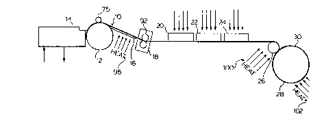
With reference now to the drawings, Figure 1 shows
schematically a line for casting a continuous metal strip.
Lead alloy strip 10 proAl~ce~ by drum 12 in combination with
n~i ~h 14 travels across heated take-off plate 16 to slitter
18 for trimming the side edges of the strip 10 and then passes
under gas heaters 20, 22 and 24 arranged in sequence to a lay-
on roll 26 for additisn~l heating prior to win~ing on mandrel
28 to form coil 30.
Figures 2 and 3 show in detail the casting drum 12
and ~llnAiQh 14. The ~lln~ i Ch 14 i8 defined by a horizontal
bottom 33, an endwall 34, and two parallel sidewalls 35 and
36. The t--n~ ~h has an inlet, ~ o~l 40 for the
introduction of molten lead alloy to feed chamber 42 defined
by endwall 34 and turbulence plate 47. Molten lead alloy
p~C~?s over a weir defined by the top of turbulence plate 47
into diverting chamber 49. A portion of the molten lead alloy
is diverted to return chamber 44 which is defined by wall 43,
floor 38, and adjustable weir 45. Adjustable weir 45, hingely
t attached to return chamber floor 38, controls the surface
height of molten lead alloy, as depicted by numeral 48. Gap
49 defined between floor 38 and the lower edge of vertical
baffle 50 allows molten lead alloy to flow into casting
chamber 52 to a height equal to height 48 in chamber 49. Lip
W094/07629 2~ ~ 612 ~ PCT/CAg3/00413
- 14 -
insert structure 60, secured to t~ iC~ 14, has a base floor
62 and parallel sidewalls 64, 66 to define the floor and sides
of casting chamber 52. The rear of chamber 52 is defined by
vertical baffle 50 and the front thereof is defined by drum
14. Lip insert 60 preferably is ma~h; n~ from graphite.
With reference now to Figure 3, lip insert structure
60, removably at~che~ to the t~n~ i ~h, has sidewalls 64, 66
with oppos~ interior surfaces preferably sloping upwardly and
outwardly away from the melt. These sloping sidewalls give
relief to the solidifying edges of the metal alloy being cast
to a strip.
With reference again to Figure 2, the casting drum
12 i6 rotatable around a horizontal axi~ 71. The outer
circumferential surface 72 of drum 12 is substantially smooth
and is, prefer~bly, conditioned by treating with a medium such
as by blasting with glass beads to provide nucleation points
for the solidification of the molten alloys. The rotatable
drum is also furni~he~ with edge rolls 75, one of which is
shown, which ensure that the edges of the metal strip 10 are
completely solidified prior to the removal of the strip 10
from the drum surface 72. The edge rolls 75 press the outer
edge on each side of the strip firmly onto the drum surface 72
to provide the nece~Ary cooling of the metal strip and
subsequently to produce the required integral edges of the
continuous cast metal strip lO. Drum 12 is internally cooled
with water, using well-known circulating means (not shown).
The diameter of the drum 12, its rotational speed, the finish
texture and the temperature of the outer surface 72 of the
~ 2146~2~
W094/07629 . PCT/CA93/00413
drum, and the temperature and the surface level 48 of the melt
in the tlln~sh, determine the amount of melt which is dragged
onto the outer surface 72 from the bath of molten metal in the
. ttlnAiFh~ thereby determining the thiC~n~cc of the strip. The
cooled drum surface 72 causes the freezing or solidification
of the molten metal into a strip lo of substantially constant
width and thickn- c,
The molten metal alloy flows from a holding vessel
(not shown) via a molten-metal centrifugal pump (not shown)
through the up-spout 40 into the feed chamber 42 and over the
weir defined by turbulence plate 47 into the diverting chamber
49. At the end of the diverting chamber 49, the metal flow is
diverted into the two flows; one upwardly over the adjustable
weir 45 into the LeL~ chamber 44, and the other through
L~ol gap 49. The molten metal alloy flowing over the
adjustable overflow weir 45 flows into return chamber 44 and
then into a holding vessel for molten alloy by way of
downspout 15. The surface level 48 is controlled by the
adjustable overflow weir 45 to ensure the proper surface level
of the molten metal in chamber 52 at drum 12. The molten
metal is pumped into t~ Ch inlet chamber 42 at a rate to
ensure that the molten metal is always in eYcecc and
continually flows over the weir 45 into .eL~.. chamber 44.
Any slag that may be formed or is cont~i n~ in the molten
metal separates easily from the melt in the tl~n~ich between
turbulence plate 47 and return chamber wall 43. The
adjustable weir 45, the flow control baffle 50 and the control
gap 49 effectively control the amount, the surface level 48
W094/07629 21 4 61 2 ~ PCT/CA93/004l3
- 16 -
and, in combination with turbulence plate 47, the turbulence
of the molten metal in the t~ h, A substantially
quiescent flow of molten metal with a substantially constant
depth (thic~neQ~) is now presentable to the rotatable drum ~2.
In presenting the molten metal to the drum surface
72, the lip insert ~tructure 60 and the drum-abutting surface
61 thereof must be of the proper design and in the proper
position. The lip insert structure 60 design must ensure that
there are no obstructions that could cause the solidifying
metal to bind to the lip insert during casting. The sides 64,
66 of the lip insert 60 thus are sloped upwardly and outwardly
away from the molten metal. The surface 63 of the lip
structure 60 abutting drum 12 must be contoured to match the
exact curvature of the drum surface 72. The po~ition of the
lip surface 63 is positioned in close proximity to the drum
surface 72 at about the "nine to ten o'clock" position. The
surface 63 does not touch the drum surface 72 as the molten
metal is transferred from the lip structure 60 to the drum
surface 72. However, too much space between the surface 63
and the drum surface 72 results in a spillout of the molten
metal and termination of the cast. Adjusting mean 65, such as
high precision guide rod-ball bearing assembly, a rack-and-
pinion or a dove-tail slide, is provided to rapidly and
accurately move t~lndich 14 and lip insert 60 towards and away
from drum 12 and its surface 72 to obtain proper positioning
and correct space 90 therebetween.
A lip insert 60 made of graphite is particularly
W094/07629 PCT/CA93/00413
well-suited for this purpose in that the graphite is softer
than the metal of drum surface 72 and surface 63 can readily
be formed for close conformity with drum surface 72 by
wrapping _and paper about drum surface 72 and abutting surface
63 against drum surface 72 while the casting drum is rotated.
In addition, graphite is well-suited in that it is not easily
wetted by the molten metal.
As the rotatable drum 14 is rotated, a predetermined
amount of molten alloy is dragged onto its casting surface 72.
The metal alloy solidifies to form strip 10 which usually
leaves the drum at about the "twelve to three o'clock"
position and fi~i ~h~ strip 10 is pulled from the rotating
drum 14 by two parallel rubber coated pull rollers 92, one of
which is shown in Figure 1, which may form part of slitting
assembly 18. The rollers 92 are driven by an adjustable
speed motor (not shown) which controls the ~peed of casting
which is adjusted to the rotation of drum 12 to achieve and
preferably contin~o~cly maintain a desired pulling tension on
the strip as it is stripped from the casting surface.
Prior to passing over lay-on roll 26, the strip is
pA~ between adjustable rotary knives in slitter 18 that
trim the outside edges of the strip to provide strip with a
precise, desired width. The strip may be p~Ce~1 over an eddy
current gauge, not shown, which continuously monitors the
thickness of the strip across its width. A digital read-out
is provided which provides the information neceCc~ry to ensure
that the strip has and can be maint~ at the desired
thiC~cs. The strip is then p~ to a torque-controlled
~ t ~ ~ , , , f t ~ ~
214~124
- 18 -
wind-up mandrel 28 for coiling.
The coiled strip in the case of low antimony-lead strip
cannot be used directly for the manufacture of battery grids, since
the coiled strip does not have sufficient resistance to fracture in
the downstream slitting and expanding operations. To increase its
resistance to fracture in the slitting and expanding operations,
the strip, immediately after casting and during coiling as a
continuous casting-heat treatment operation, or by a subsequent
batch treatment of coils, is subjected to heat treatment. The low
antimony-lead alloy strip is heated to a temperature above about
190~C, preferably to a temperature in the range of about 200~C to
230~C, and maintained at the elevated temperature for at least
about 10 minutes to homogenize the antimony as a fine dispersion in
the lead matrix, thereby acquiring expandability with good
integrity and strength. The heat treatment of the low antimony
lead enables the successful production of expanded mesA battery
grids with superior electrochemical characteristics without
breakage.
The invention will now be illustrated by the following
non-limitative example.
BXAMPLE
A typical low antimony-lead alloy having a composition
comprised by weight of 1.8% Sb, 0.15% As, 0.16-0.2% Sn, and the
balance lead, was heated to about 400~C in the tundish 14 of the
invention and cast at a speed 0.18-0.19 metres/second (36-38
feet/minute) with a gauge of 5.52 mm (0.217 inch) cast and strip
~ 3S~
~ 21~6124
-- 19 --
width of 9.15 cm (3.604 inch) on a drum surface which had been
prepared by blasting with glass beads. The strip temperature on
the drum 12 at top centre was 140~C, the drum periphery being
cooled by water circulating through the drum at a temperature
between 38 - 43~C (100-110~F). The strip travelled across a
0.61 m (24 inch) long heated take-off plate heated to 190~C in the
centre of the plate by four 0.33 m (13 inch) 125 watt strip heaters
98 to provide a strip temperature of about 170~C.
The strip was then passed through slitter 18 under
tension of draw rollers 92 for trimming of the strip edges and
passed 3.0 m (10 feet) under heaters 20,22 and 24 each 10 cm (4
inches) wide and 0.91 m (36 inches) long to lay-on role 26. The
heaters 20, 22 and 24 were each fitted with 10 cm (4 inch) metal
sides and a top to partially enclose the strip passing
therethrough. It is desired to heat the strip to at least 190~C
and maintain the strip at that temperature for at least lo minutes
to acquire ~xr~n~hility with good integrity and strength. Heater
20 preferably provides the highest temperature with heaters 22 and
24 providing somewhat lower temperatures to heat strip 10 to a
target t~mperature of about 200~C. Supplementary heat, such as by
an acetylene torch 100, preferably indirectly heats the strip to
above 200~C by applying heat to lay-on role 26. Heat is applied to
the coil at 102 by a spreader flame fuelled by propane to retard
cooling of the coil.
The strip can be heated continuously during production as
shown in Figure 1 and maintained at an elevated temperature of at
'J ~ i ~
., r
~ 2146 1 2~
- 19 A -
least 190~C in the coil 30 for at least 10 minutes before being
slowly cooled. Alternatively, the produced strip can be directly
wound on a mandrel to form a...
~3~
~ 21~6~2~
W094/07629 PCT/CA93/00413
- 20 -
coil without heating, and permitted to cool. The coil can be
subjected to a desired heat treatment by the manufacturer of
the battery grids at a later dateO
The prQsent invention provides a number of important
advantages. The strip proA-~c~ by the method of the invention
is substantially free of porosity, has smooth surfaces, and
has a predetermined and precise width and a predetermined,
substantially even and constant thiC~n~c~. The thick~ of
the strip is such that grids made from the strip may be
th;nn~r than conventional battery grids made according to
prior art proce~~~. The thi~ne~s of strip may be in the
range of about 0.5 to 1.0 mm which is about 50~ of the
thickness of prior art grids. The ~h i nner grids enable the
battery manufacturer to make batteries that have a higher
energy and power densities. The grids are resistant to
corrosion and to creep during use and have been found to be
superior to wrought grids of the same composition proAI~ceA by
slab casting and roll working.
It will be understood that temperatures and duration
of heating may vary according to the alloy composition and
according to the heat treatment desired.
It will also be understood that modifications can be
made in the embodiment of the invention illustrated and
- described herein without departing from the scope and purview
of the invention as defined by the appenA~ claims.