Note: Descriptions are shown in the official language in which they were submitted.
21~65~2
TITLE: CONTROLLING MECHANISM FOR A FOLDING 81CYCLE
BACKGROUND OF THE INVENTION
The present invention relates to a controlling mechanism, more
particularly, to a controlling mechanism for a folding bicycle which
s facilitates a simple configuration to lower its manufacturing cost and a
easy operations for any user.
The invention of the bicyclecan be retracted to theChineseancient
time1 the Three-Nations time. According to the saying, the bicycle was
first invented by Chu~er-Liang1 accordingly,-the bicycle is also called
10 ' Ku n-Mi n Veh icle
In the area or in the past where the motorcycle and cars are not
very popular, the bicycle was mainly used as a transportation tool. 8ut
gradually, the motorcycle and vehicles and other transportation become
more and more popular, the bicycle is seldom used as a transportation
15 tool but a sporting equipment. Now people uses bicycle as a
transportation only in a short distance.
On the other hand, in the modern city, tlte space of an apartment
which a family or an individual can use is rather small. Hence1 there is
a small room for storing a bicycle in one1s house. Besides, it is also not
20 convenient for people who Iives in forth floor to take a bicycle up and
down everyday. If one just leaves his bicycle outside1 then he must face
the risk of being stolen.
In order to sotve the problem which a conventional bicycle met, a
folding bicycle wherein the bicycle can be fully extended to function as
25 a normal bicycle and is folded to compact bulk for easy storage. The
2146532
-
i n ven t ion of t h is fol d ;n g b icycle real I y sol ve t he p rob lem wh ich a
conventional bicycle met. But the connecting mechanism used in the
folding bicycle is quite complicated which makes the manufacturing cost
to a comparatively high. Meanwhile, the operation of such cQntrolling
5 mechanism is also quite difficult and inconvenient. Besides, the stem of
the handlebar of a conventional bicycle, folding or not folding, is fixed
to the fork tube. Accordingly, the height of the handlebar is not
ad justable for different user. Hence, if the bicycle is suitable for a user
with small height, then it will be very inconvenient for a people with
0 relative small height to ride it.
S(JMMARY OF THE INVENTION
It is the ob ject of this invention to provide an improved controlling
mechanism for a folding bicycie wherein the configuration is simple and
the operation ~s convenient.
It is still the object of this invention to provide an improved
controlling mechanism for a folding bicycle wherein a telescopic
mechanism is disposed between the stem and a fork member to facilitate
an ad justment of the height of the handlebar.
I n order to achieve the ob jects set forth, the controlling mechanism
ZO made according to this invention includes a frame member which is
combined by a first or front frame member and second or rear frame
member. A coupling mechanism is provided at the second or rear frame
in such a manner that the first or front frame member can pivotedly
disposed thereof. ~y the actuation of the coupling mechanism, the first
2s f rame member can be folded onto the second f rame member for easy
stora~e or fully extended from a retracted position for a normal riding.
2146532
~~ According to one aspect of the controlling mechanism made
according to this invention, a retaining means is disposed at the
controlling mechanism for fixing the first frame member and the second
frame member from rotating with respect to each other.
s According to another aspect of the controlling mechanism made
according to this invention, a telescopic mechanism is disposed at the
stem of the handlebar for height ad justment. By this arrangement, the
handlebar can be ad justed to any height for easy maneuvers of it.
BRIEF DESCRIPTION OF THE DRAWINGS
The structural and operational characteristics of the present
invention and its advantagas as compared to the known state of the prior
art will be better understood from the following description, in
con junction with theattached drawingswhich show illustratively but not
restrictively an example of a controlling mechanism for a fordable
bicycle. in the drawings: -
Figure 1 is an exploded perspective view showing the controlling
mechanism of the front and the rear frame member;
Figure 2 is a side elevational view of the controlling mechanism
wherein the front frame member and the rear frame member are
20 completely connected by the coupling mechanism;
Figure 3 is still a side elevational view of the controlling mechanism
wherein the coupling mechanism is separately with each other;
Figure 4 is a sketch view of a bicycle incorporated with a
controlling made according to this invention, wherein the front frame
25 member and the rear front member are fully extended;
Figure 5 is a sketch view of a bicycle incorporated with a
2146532
~_ controlling made acc~rding to this invention, wherein the front frame
member and the rear front member are fully folded with each other;
Figure 6 is a perspective exploded view of a telescopic mechanism
incorporated with the stem of the handlebar;
sFigure 7 is an cross sectional vive view of a telescopic mechanism
incorporated with the stem of the handlebar;
Figure 8 is a sketch view similar to Figure 7 wherein the stem is
moved to a lower position;
Figure 9 is an end view of the telescopic mechanism incorporated
o with the stem; and
Figure 10 is still an end view of the telescopic mechanism similar to
Figure 9 wherein the mechanism is moved to a second position.
DETAILED DESCRIPTION OF A PREFERABLE EMBODIMENT
Referring to Figures 1 to 4, the frame member of the bicycle is
separated into a fi rst or f ront f rame member 4and a second or rear f rame
member 5. The front frame member 4 and the rear frame member 5 are
configured in such a manner that those two frame members 4 and 5 are
easily folded together to minimize the bulk size.
The f ront f rame member 4 generally includes a coupling tube 1 and
a head tube 110 and a pair of parallel supporting tubes 42, 41 bridging
the coupling tube 1 and the head tube 110. A front fork member 6 can
rotatably install with said head tube 110 and connect a stem 71 of a
handlebar 7. A front wheel 61 is installed to the fork tip 62 of the fork
member 6.
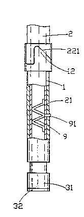
~5 ~he front frame member 5 generally includes a coupling shaft 21,
a seat post 2, a horizontal supporting tube 3 and an inclined supporting
--4--
2146532
~,
tube 51. A seat 8 is installed to the seat post 2. A rear wheel ~2 is
installed to the rear f rame member 5.
The coupling mechanism C generally includes a coupling tube 1
which forms also a part of the f ront f rame member 4 and a coupling shaft
5 21 which forms also a part of the rear f rame member 5. By this provision,
the coupling tube 1 can be rotatably mounted to the coupling shaft 21.
No referring to Figure 1, detailed description of the coupling
mechanism C is given. The coupling tube 1 defines a upper end, a lower
end and a outer wall. A through hole 10 is provided at the outer wall of
10 the coupling tube 1. The axis of the hole 10 is perpendicular to the plane
defined by the front frame member 4. A flange member 11 is provided at
the upper end of the coupling tube 1. A contoured portion 12 is provided
at the flange member 11 and a sloped portion 13 is formed ad jacent to the
contoured portion 12. The coupling tube 1 further i~ncludes a slit 131 at
15 the upper end. A pair of lug members with threaded hole are disposed
at both sides of the slit 131. An ad justing handle-14 is mounted on the
lug member for controlling the inner diameter of the coupling tube 1 at
the upper end.
The coupling shaft 21 is extended from the seat tube 2 and defines
20 an upper end, a lower end and a outer wall portion. The outer diameter
of the coupling shaft 21 is small than the inner diameter of the coupling
tube 1 in such a manner that the coupling tube 1 can sleeve onto the
coupling shaft 21. A positioning hole 210 is provided at the outer wall of
the coupling shaft 21 re~;pect to the through hole 10 of ~he coupling tubè
2s 1. A collar 22 is disposed at the upper end of the coupling shaft 21. The
collar 22 has contoured recess portion 221 which defines a vertical
2146532
~~ stopper 223 and a sloped receiving portion 222. The contour portion 12
of t he f lan ge membe r 1 1 can be comp letel y an d compact I y recei ved wi th
the contoured recess portion 221, accordingly, the sloped portions 222
and 13 are meshed completely.
S Besides, the total length of the coupling shaft 21 is longer than the
total length of the coupling tube 1. By this arrangement, the coupling
tube 1 can be rotatably and slidably sleeved to the coupling shaft 21 and
makes a movement between a folded position and a unfolded position.
The coupling socket 31 is provided at the end of the horizontal
0 supporting tube 3 for receiving and retaining the lower end of the
coupling shaft 21 therein.
A biasing spring member 9 having aW-shape is disposed within the
coupling tube 21. The biasing spring member 9 further includes a boss
91 which can pass through the positioning hole 210 and the through hole
10 to position the coupling tube 1 and the coupling shaft 21 with each
other when the contour portion 12 of the flange member 13 is completely
and compactly received by the contoured recess portion 221.
A lid 32 is provided to cover the lower end of the coupling socket
31 to prevent the dust or water enter the coupling shaft 21.
In assembling, the biasing spring member 9 is firstly disposed
within the coupling shaft 21 in such a manner that the boss 91 is
projected from the positioning hole 210. Then loosen handle 14and make
the coupling tube 1 be easily sleeve onto the coupling shaft 21. The
contoured portion 12 and the sloped portion 13 can be completely meshed
2S with the contoured recess portion 221 and the sloped portion 222. The
coupling socket 31 is then attached to the lower end of the coupling shaft
214653
'_
21 to retain the coupling tube 1 from be removed thereof. At last, the lid
42 is attached to the lower end of the coupling socket 31 to complete the
assem b l y .
When the boss 41 is projected into the through hole 10, the
contoured portion 12 and the sloped portion 13 is completely meshed with
the contoured recess portion 221 and the sloped portion 222 as well, then
tighten the handle 14 to lock the coupling tube 1 to the coupling shaft 21,
the front frame member 4 is completely positioned to the rear frame
member 5 and construct a complete frame member for normal riding.
I0 As shown in Figures 2 and 4, the contoured portion 12 and the
sloped portion 13 is completely meshed with the contou red recess portion
221 and the sloped portion 222. Accordingly, the front frame member 4
is unfolded from the rear frame member 5. The handle 14 can be
tightened to lock coupling tube 1 with respect to t~e coupl-ing shaft 21.-
lS As shown in Figures 3 and 5, the contoured portion 12 and the
sloped portion 13 is completely released from the contoured recess
portion 221 and the sloped portion 222. Accordingly, the front frame
member 4 is able to fold to the rear frame member 5. Again, the handle 14
can be tightened to loc~< coupling tube 1 with respect to the coupling
shaft 21 when the front frame member 4 is completely folded onto the
rea r f rame mem be r 5 .
Referring to Figures 6 to 10, a preferable embodiment of the
telescopic mechanism made according to this invention. The head tube
110 having a hollow central portion 1102 is provided with a threaded
portion 1101 at the top portion. A washer 1103, a collar 1105 and a
washer 11~4 can be mounted to the threaded portion 1101. By this
--7--
21g6532
'-
arrangement, the tube 15 having a inner threaded portion 153 can be
screwed to the head tube 110 by the engagement of the threaded
portions 1101 and 153. A vertical slot 151 and a horizontal slot 152
ad jacent to the vertical slot 151 is provided at the inner wall of the tube
s 15. A lower compressed spring 155, a retaining body 16 having a
projected portion 161 and a upper compressed spring 154 are inserted
into the hollow portion defined by the head tube 1101 and the tube 15
orderly. A inner tube 17 having a project post 171 with respect to the
vertical slot 151 and horizontal slot 152 is inserted to space defined by
lG the hollow partion defined by the head tube 1101 and the tube 15. The
inner tube 17 further includes an acute end 172 with respect to the
projected portion 161 of the retaining body 16. A central rod 18 having
a threaded lower end portion 181 is inserted into the inner tube 17 and
then engages with the threaded portion of the retaining body 16. At last,
a retaining ring 174 is mounted to the upper end of the tube 15 to
prevent the elements from being removed. The retaining ring 174 is
provided with a pair of inner slot 1741 with respect to the vertical slot
151 of the tube 15. By this arrangement, when a maintenance work is
necessary, the retaining ring 174 cari be loosened first, then rotate a
certain angle in such a manner that the inner slot 1741 is in alignment
with the vertical slot 151, then the inner tube 17 can be pulled out. By
this arrangement, the lower compressed spring 155 is positioned to the
bottom of the head tube 110 and the lower portion of the retaining body
16. Meanwhile, the upper compressed spring 154 is disposed between the
2s position ~etween the retaining body 16 and the biasing tube 173.
Accordingly, the central rod 18 is ready to moved upwardly or
2146532
downward, as better shown in Figures 7 and 9. If a downward force is
applied, the central rod 18 can move the inner tube 17 downward. Then
by rotating the handlebar 182 of the central rod 18, the inner tube 17 i
rotated in such a manner that the post 171 is retained within the
horizontal slot 152, as better shown in Figures 8 and 10. A reverse
operation procedures will make the central post 18 jump upwardly
automatical I y .
Although the present invention has been described in connection
with the preferred embodiments thereof, many other variations and
modifications will now become apparent to those skilled in the art without
departing from the scope of the invention. It is preferred, therefore,
that the present invention not be limited by the specific disclosure
herein, but only by the appended claims.