Note: Descriptions are shown in the official language in which they were submitted.
21~6~5
,. ...
A DECORATIVE DEBOSSED RIGID PAPERBOARD
CONl AINER AND METHOD OF FORMING THE SAME
TFCHNICAT FIFT 1~
nle pres~nt invention relates generally to the formation of
pap~rboard containers and more particularly to a rigid paperboard container
having a decorative debossed por~ion and method of forming such
decorative debossed portion.
RACKGROUND OF THF INVFNTION
Formed fiber containers, such as paper plates and trays, are
commonly produced either by molding fibers from a pulp slurry into the
desired form of the container or by pressing a paperboard blank between
dies into the desired shape. The molded pulp articles, after drying, are
fairly strong and rigid but general~y have rough surface characteristics and
are not susceptible to printing or other means of decorating such container.
Pressed paperboard containers, on the other hand, can be decorated and
coated with a liquid-proof coating be~ore being stamped by the forming dies
into the desired shape. Pressed paperboard containers generally cost less
and require less storage space than the molded pulp articles.
During the formation of the pressed paperboard containers, sheets of
paperboard material are blanked in order to forrn an initial substantially
planar container blank which is subsequently placed between forming dies
and pressed into the desired configuration. Presently, in order to form a
decorative configuration on the paperboard container, the blank either
before or after the blanking process is decorated by a printing press which
prints a decorative pattern on any desired portion of the paperboard
container. Most often, the decorative printing is placed about the outer
periphery of the paperboard container.
- 2 - ~ 6 ~ 5
Because the paperboard blanks are pleplilll~d with a decorative pattern, it is
necessary to ensure the ~lignm~nt of the blank within the press when forming such decorative
paperboard containers. This results in higher m~mlf~rtllring costs due to the requisite
tolerance within which the paperboard blank must be placed between the cooperating dies and
the number of mi~ n~ paperboard containers which must be discarded because the
decorative pattern is mi~ligned with respect to the formed container.
Additionally, as is discussed in U.S. Patent No. 4,721,499 issued to Marx et
al. And assigned to the assignee of the subject invention, it is desirable to form densified
regions in the form of cir~;ulllrerelllially spaced pleats formed in the sidewall rim and lip of
the container in order to add strength to the overall container structure. In doing so, the pleats
often intersect the decorative pattern which has been previously placed on the container
resulting in a container which is not aesthetically pleasing to the consumer, particularly if such
decorative pattern is a word or a phrase which is obscured by the densified regions.
Accordingly, there is clearly a need for a container having a visible decorative
pattern formed thereon which is not obscured by either mi~lignment of the paperboard blank
during formation of the container or the formation of densified regions for adding rigidity to
the overall container structure. Additionally, there is a need for a decorative paperboard
container which can be m~nllf~rtllred in an economical manner wherein the formation of
defective containers is minimi7e~1 without sacrificing the time incurred in forming the
container. Moreover, this is a need for a container including a decorative surface which is
appealing to
. :...2 -
2146fi~5
' ,..
th~ consumer and which can be manufactured without the addition of cost~
associated with printing such a decorative pattern.
SUMMARY OF THF INVFN-llON
It is the primary object of the present invention to overcome the
above noted shortcomings associated with prior art paperboard containers
and their method of manufacture.
A further object of the present invention is to provide a decorative
paperboard container which can be manufactured in an economical manner
without adding to the steps of present manufacturing processes.
Yet another object of the present invention is to reduce the overall
manufacturing costs associated with the formation of decorative paperboard
containers by reducing the number of defectively formed containers.
An additional object of the present invention is to provide a method
of manufacturing paperboard containers wherein the overall strength of the
paperboard container is increased without destroying the decorative
formation on the paperboard containers.
An additional object of the present invention is to provide a
paperboard container which is manufactured at a reduced cost and which
includes a decorative pattern which is not obscured during the process of
forming such a container.
Yet another object of the present invention is to form a paperboard
container wherein the decorative aspects of the container are formed
substantially simultaneously with the formation of the container from a
substantially flat paperboard blank.
A further object of the present invention is to provide a proc~ess for
manufacturing decorative paperboard containers while reducing the
21~669~
_ - 4 -
necessary steps of present manufacturing process thus reducing overall
manufacturing costs.
These as well as additional objects of the present invention are
achieved by forrning a paperboard container by initially forming a flat
paperboard blank having an outer periphery and positioning the blank
between an upper and lower die assembly with the surfaces of the upper
and lower die assemblies defining a finished container including a bottom
wall, side wall, a planar rim substantially parallel to the bottom wall and a
lip extending from a periphery of the planar rim with at least one of the
upper and lower die assemblies including an element for forming a
decorative pattern in at least the planar rim portion of the container and
subsequently pressing the die assembly surfaces together to form the
container having the decorative panern integrally formed in the planar rim
portion of the container. The container is formed from a blank that
includes a substantially planar inner region, a side wall region including a
generally annular side wall extending upwardly from a periphery of the
planar inner region and the rim region extending generally outwardly from
a periphery of the side wall region with the rim region including a
decorative panern formed integrally therein. The container may also
include a plurality of circumferentially spaced densified regions radially
extending through the rim region with the densified regions including
substantially three layers of paperboard material. In such a case, the
decorative pattern which is debossed into an upper surface of the rim region
may be intersected by the radially extending densified regions without
obscuring the decorative pattern.
These as well as additional advantages will become apparent from the
following detailed description when read in light of the several figures.
214663~
~!
BE~F nFSCl~llON OF THF DRA~NGS
Figure 1 is a top view of a paperboard container formed in
accordance with the present invention.
Figure 2 is a cross sectional view t~cen along line 2-2 of Figure 1.
Figure 3 is a cross sectional view of the upper and lower die
assemblies for forrning a paperboard container in accordance with the
present invention.
Figure 4 is a cross sectional perspective view of a paperboard
container forrned in accordance with an alternative embodiment of the
present invention.
Figure 5 is a cross sectional view of a blank for forming the
container of the present invention before such fonning process.
Figure 5A is a cross sectional view ta~en along line 5-5 of Figure 4.
DETArLED DESCR~PTION OF THE PREFERRED EMBODIM~NTS
Reference will now be made in detail to the preferred embodiment
of the present invention, an example which is set forth in the above noted
drawings. In accordance with the present invention, the paperboard
container comprises a substantially planar inner region, a side wall region
and a rim region adjoined to and extend;ng about the periphery of the
planar region. The container of the present invention may be formed into
a plate or bowl thus having a circular configuration or such container may
be square or rectangular in shape having angular corners such as a tray.
Further, additional shapes are contemplated including compartmented trays
and plates as well as oval platters. In each of the contemplated
embodiments, the container includes a rim region having at least one
substantially planar portion.
- 214~6~5
- 6 -
As illustrated in Figure 1, the container 10 includes a substantially
planar inner region 12 which is surrounded about its periphery by side wall
region 11 and adjoining rim region 13. The side wall region 11 includes
a generally annular region 14 which flares upwardly and outwardly from a
periphery of the planar inner region 12 and a first frusto-conical region 16
which slopes upwardly and outwardly from a periphery of the annular
region 14. These features being illustrated in detail in Figure 2. In the rim
region 13, outwardly flaring arcuate annular region 18 adjoining an outer
periphery of the frusto-conical region 16 is provided with: first portion 20
thereof extending generally upwardly from the first frusto-conical region
16; and a second portion 22 thereof flaring generally outwardly from the
annular region 18. A substantially planar region 24 extends substantially
tangentially from the second portion 22 of the arcuate annular region 18 and
thus extends outwardly from such second portion 22 of the arcuate annular
region 18. The planar region 24 may be slightly inclined with respect to
the substantially planar inner region 12, however, the region 24 is
preferably inclined slightly downwardly in order to add strength to the rim
portion of the container. Adjoining the outer periphery of the planar region
24 is an outwardly and downwardly flaring frusto-conical lip 26 which both
adds significantly to the strength of the container and aids the consumer in
grasping the periphery of the container 10
With reference to Figure 4, the phantom lines 28, 30, 32, 34 and 36
are provided for ease in identifying the various structural segments of the
container and do not represent lines actually appearing on the container.
Moreover, the phantom lines do not represent actual demarcations between
the sections in that, as explained in greater detail hereinbelow the size
relationships between the segments may vary without departing from the
214~9~
- 7 -
spirit and scope of the present invention. Additionally, as is illustrated in
Figure 2, the container is forrned from an integral unitary paperboard
blank.
As can be seen from Figure l, the paperboard container 10 includes
a decorative pattern about planar region 24 with this decorative pattern
including alternating shells and scrolls. It should be appreciated that the
particular decorative pattern is not of importance with respect to the subject
invention but merely the manner in which the decorative pattern is created.
This decorative pattern may be any suitable configuration or may be words
or slogans formed about the periphery of the container. As will be
discussed in greater detail hereinbelow, the decorative pattern is integrally
forrned in the planar region 24 of the paperboard container lO as is
illustrated in Figure 2. The debossed regions 40 are formed substantially
simultaneously with the formation of the remaining portions of the
container. That is, during the formation of the side wall reg;on 11, planar
region 24 and lip 26, a decorative pattern formed in the forming die
debosses the planar region of ~he paperboard container with any desired
decorative pattern. It should be noted that while the decorative pattern is
illustrated as being formed in the planar region 24 of the paperboard
container 10, such decorative pattern may be simultaneously formed in
other regions of the paperboard container as well.
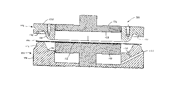
Referring now to ~igure 3, a die assembly for forming the
paperboard container in a manner set forth hereinabove is illustrated in
detail. A die assembly 100 includes an upper die assembly 102 and a lower
die assembly 104. Typically, the lower die assembly 104 is maintained in
a substantially stationary position while the upper die assembly 102 is
pressed into contact with an upper surface of a paperboard blank plac~d
21~66~
- 8 -
therebetween. However, it is possible with this arrangement to move the
di~ assemblies in any manner so long as the paperboard blan~ is sufficiently
formed into a paperboard container.
As discussed hereinabove, the upper die assembly 102 and lower die
assembly 10~ are utilized to press a flat circular paperboard blank 106 into
the shape of the paperboard container 10. The construction of the upper
and lower die assemblies and the equipment which is utilized to maneuver
such assemblies is substantially conventional. To facilitate the holding and
shaping of the blank 106, the dies are segmented in the manner shown.
The lower die assembly 104 includes a circular base portion 108 and a
central circular platform 110 which is mounted to be movable with respect
to the base 108. The platform 110 is cam operated in a conventional
manner and urged toward a normal position such that its flat top forming
surface 112 is initially above the forming surfaces 114 of the base 108.
The platforrn 110 is mounted for a sliding movement with respect to the
base 108 with the entire base 108 being mounted in a conventional manner.
Because the blank is very tightly pressed at the peripheral area, moisture in
the paperboard which is driven therefrom during pressing of the heated dies
is released by providing a circular groove 120 which vents to the
atmosphere throu~ a passageway 122.
Similarly, the top die assembly 102 is segmented into a circular ring
portion 124 and a central platform 126 having a flat forming surface 12~.
The ring portion 124 has complementary forming surfaces 130 which
complement the forming surface 114 of the lower die assembly 104. The
central platform 126 and ring 124 are slidingly mounted with respect to one
another. The forming surface 130 of the upper die assembly further
includes deboss elements 132 which are spaced about the periphery of the
' 214~6~
.
g
portion of the fo~ming surface 130 which forrns the planar region 24 of the
papelboard container. The significance of such debossing elements will be
explained in greater detail h~reinbelow Further, it should be noted that the
debossing elements may be formed at any position along the forming
surface 130 or may even be formed on the planar surface 12~ of the
platform 126.
In the pressing operation, the blank 106 is first laid upon the flat
forming surface 112 of the platform 110, generally underlying what is to
be the inner generally planar region 12 of the paperboard container.
Initially, the surface 128 of the platform 126 contacts an upper surface of
the paperboard blank 106 to hold the blank in place as the forming
operation begins. Further downward movement of the upper die assembly
102 brings the sprin~ biased forming surface 130 of the outer ring 124 into
contact with the edges of the blank 106 to begin to shape the edges of the
blank over the underlying surfaces 114 in the areas which will define the
side wall 11, planar region 24 and lip 26 of the paperboard container 10.
Eventua~ly, the upper die assembly 102 moves sufficiently far down so that
the platforms 110 and 126 and the ring 124 are fully compressed such that
the adjacent por~ions of the forming surfaces 128 and 130 are co-planar and
the adjacent portions of forming surfaces 112 and 114 are co-planar. The
upper die assembly 102 then continues to move downwardly and thus drives
the entire lower d;e assembly 104 downwardly against the force of springs
(not shown) which support the lower die assembly 104. At the full extent
of the downward stroke of the upper die assembly 102, the die exert a force
on one another through the formed blank 106. Further, the embossing
elements 132 are pressed into an upper surface of the planar region 124 of
2146!~9~
. ~,~",
10 -
the paperboard blank 106 thus forming a decorative pattern in the desired
region of the paperboard container.
In order to aid in the forrnation of the paperboard container, the
upper and lower die assemblies 102 and 104 are maintained at a
temperature in the range of 200~ F to 400~ F and preferably in the range
of 250~ F to 350~ F. Further, during the formation step, the upper and
lower die assemblies 102 and 104 are pressed against one another at a
pressure in the range of 200 psi to l S00 psi. The paperboard stock used for
the blank preferably has a basis weight in the range of 100 pounds to 400
pounds per ream (3,000 sq. ft.) and a thickness or caliper in the range of
0.008 inches to O.OS0 inches. It should be noted, however, that any
conventional paperboard stock may be used in forming the paperboard
containers in accordance with the present invention.
Referring now to Figures 4, 5 and SA, the present invention is also
contemplated for use in paperboard containers formed in accordance with
that method set forth ;n U.S. Patent No. 4,721~499 and U.S. Patent No.
S,242, 10~ each of which are assigned to the assignee of the subject
invention and hereby incorporated herein by reference. As can be seen
from Figure 4, the paperboard container 10 includes a bottom wall 12
upwardly extending side wall 14, first curved section 16 adjoining the side
wall 14 to the periphery of the bottom wall 12 and a rim 18 with a curved
portion 20 adjoining rim 18 with the periphery of the side wall 14 and a
downwardly curved lip 22 outwardly extending from the periphery of the
rim 18. Again, the phantom lines in Figure 4 have been provided for ease
in identifying the various structural segments of the container and do not
represent lines actually appearing on the container. The container further
includes a plurality of densified regions 25 radially extending through and
21466~S
circumferentially spaced about the ~nnul~r section of side wall 14, the
curved portion 20 and the rim 18. These densified regions are forrned from
pleats S0, exaggeratedly represented in Figure 5 including at least three
layers 52, 54 and 56 of paperboard material created by score lines during
forrning of the container blan~. These pleats are subjected to sufficient
pressure to reforrn the fibers of the separate layers 52, 54 and 56 of the
paperboard into a cohesive fiber structure having a thickness subst~nti~lly
equal to the remaining portion of the paperboard material as is illustrated
in ~igure SA.
Reformation of the pleats into a cohesive fibrous structure
substantially strengthens the weakest part of the pressed paperboard
container. Where the pleats no longer comprise separate layers of the
paperboard, there is no tendency for the container to return to its original
shape. Indeed, the densified regions resist efforts to flatten the side wall of
the rim as such would require increasing the area of the side wall and the
rim. In a 9" plate formed in accordance with the present invention, the side
wall second curved portion and rim receive a pressure in excess of 500 psi
thereby substantially increasing the density in the radially extending
densified regions. ~urther, because the decorative pattern is formed
substantially simultaneously with the forrnation of the paperboard container,
the decorative pattern may intersect the densified regions without
significantly affecting the image debossed into the paperboard material.
With prior art decorating processes which print a decorative pattern on the
paperboard container, the decorative pattern would become signific~ntly
obscured with the formation of the densified regions. Accordingly, with
Applicants' invention, a clear and precise decorative pattern can be formed
in the rim region of the paperboard container even if such rim includes the
2146~9~
- 12 -
above noted densified regions. While Figures 4 and 5A illustrate the
preferred positioning of the decorative pattern, that is, the pattern being
formed adjacent th~ de~,ified regions, as discussed hereinabove such
positioning is not essential to the formation of the decorative pattern in
accordance with the present invention in that the decorative pattern can be
integrally formed in the densified regions as well.
While the present invention has been described with reference to
preferred embodiments, it will be appreciated by those skilled in the art that
the invention may be practiced otherwise than as specifically described
herein without departing from the spirit and scope of the invention. It is,
therefore, to be understood that the spirit and scope of the invention be
limited only by the appended claims.
TNDUSTRIAL APPLICABI~ITY
Containers formed in accordance with the foregoing description may
be manufactured by existing manufacturing assemblies with only minor
changes being made to the upper die assembly for forming the decorative
pattern in an upper surface of a paperboard container. The container set
forth hereinabove may be circular as in a plate or bowl, or may be square
or rectangular with annular corners such as a tray where it is desired to
form a decorative pattern in a portion of the upper surface of the
paperboard container.