Note: Descriptions are shown in the official language in which they were submitted.
W O 94/09845 2 1 ~ 6 8 5 7 PC~r/US93/09454
1
INTRAVASCULAR CA 1 H~ 1 ~K WITH INFUSION ARRAY
CROSS-RE~RENCE TO RELATED APPLICATIONS
This is a con~inll~tion-in-part of appli~tion Serial No. 07/969,595, filed
November 2, 1992, the complete ~licclosllre of which is inco-~ul~ted herein by
reference.
BACKGROIJND OF THE INVENTION
This invention relates genPr~lly to drug-delivery devices, and more
specific~lly to intravascular catheters ~or delivery of therapeutic agents from within a
lumen of a blood vessel or other body organ.
In percutaneous tr~nclnmin~l angioplasty procedures, a catheter having an
S e~p~nA~hle distal end, usually in the form of a balloon, is positioned in a lumen of a
blood vessel with the distal end disposed within a stenotic atherosclerotic region of the
vessel. The exp~nA~hle end is then exp~nAPA to dilatate the vessel and restore adequate
blood flow through the region of stpnosic.
Whereas angioplasty has gained wide acceptance, it co..l;....es to be
10 pl~gued by two major problems, abrupt closure and restPno~cis. Abrupt closure refers
he acute ccrl-lcion of a vessel imm~Ai~tPly after or within the initial hours following
the dilatation procedure. This type of complir~tion, occ~lrring in ayp.u~ tely one in
twenty cases, frequently results in myoca.~lial infarction and death if blood flow is not
quickly ~ ored. The ~ dly meçll~nicmc of abrupt closures are arterial Aicsection15 and/or thrombosis. It is pOSh~i~p~ that the ability to deliver agent (e.g. ana ~ -o--,botic drug) directly into the arterial wall at the ti ne of angioplasty would
reduce the in~iA~Pnce of thrombotic acute closure.
~ steno~sic refers to the re-ll~.uwillg of an artery after an initially
successfi-l angioplasty. Restenosis usually occurs within the initial six monthc after
20 angioplasty. It is pos~ tPd that the delivery of certain agents directly into the arterial
wall would interrupt the ce~ r events I~Aing to restpnosic.
WO 94/09845 Pcr/uss3/o9454
21468~7 2 ~
The potentiai utility of local intr~mllral drug delivery is not ~imited to
atherosclerotic coronary artery disease. Other sites of atherosclerosis (e.g. renal, iliac,
femoral, distal leg and carotid arteries as well as saphenous vein grafts, synthetic grafts
and arteriovenous shunts used for hemo~i~lysis) would also be approl)liaLe for local
S ;~ dl drug delivery. Local illLI~ulluldl therapy may also prove effir~rious in non-
arterial structures, inrhl~ing the prostate via the prostatic urethra (benign prostatic
l~y~;lLIv~hy~ pro~ ;l;c and adenocarcinoma), fallopian tubes via its lumen (strictures),
and brain parenchyma (p~rkinson~s Disease).
At present, intravenous mP~ ti~ c are delivered ~y~lf .~iç~lly by vein or
10 regionally (e.g. intracoronary inf(-cit n). Systemic delivery is generally not well suited
to the L-~ P---t of disease entities with a single site or several discrete sites of illL~
(e.g., corol~a-~ artery disease) in that it npcec~it~tps: tl) exposing sites other than the
site of interest to mPdic~tion where it may have an adverse effect; (2) inf~lcing
sllfficient qu~nti*Ps of agent to achieve the conrenttation throughout the entire volume
15 of distribution; and (3) exposing the agent to depr~*on and çlimin~tion by one or
more organ systems remote from the site of in~lf~L. Fu.Lll~,l.llore, the tissue
con- ent~tion that can be achieved at the site of in~l~ sl is often li nited by the effects
of the agent at distant sites. Local illll~LlllUldl delivery obviates these problems.
Therefore, it is of particular l.ll~ol~ce to deliver the the.~ e~l;c agent directly to the
20 ~ t site by cont~ct with or ~nçt~l;on into the tissue, rather than simply relP~cing
the agent into the blood ~tre~n in the vicinity of the tre~tmPnt site.
While various c~ have been developed for delivery of agents to a
L~ l site within a vessel or organ lumen, such devices have ~llr~l~d from certain
drawbacks. Ln particular, known agent delivery c~th~t~rs gçne!~lly do not permit25 delivery of an agent directly to a t,e~ t site indepen~çr.tly of the deploy.,.ent of the
delivery ~ çh~ rent the lumen wall. For eY~mplP, known agent delivery
r~thPters frequently employ an exr~n~l~hle member such as a balloon which is
eYp~nded near the L~ t.-.~ -t site and brought into contact with the lumen wall. A
Ihel~ c agent is usually delivered ~hrough pores on the surface of the balloon. In
30 such devices, the pressllri7~d fluid which expands the balloon is also the vehicle for the
agent. Therefore, the balloon cannot be eYr~ndPd without expell~ng the drug/vehicle
n~ixture. This sch~me is in~.fficien~, in that agent is expelled before the ~ hely of
Wo 94/09845 2 1 ~ 6 8 5 7 PCr/US93/09454
.. .. .
the balloon is adjacent to the lumen wall. This scheme also prevents delivery of agent
without at least partly exp~n~ing the balloon. The deployment rnech~nicm (i.e. balloon
exp~ncion) and the drug delivery m~ch~ni~m are inextri~hly linked.
Thus, where it would be desirable to ~ t~t~ a region of stenQcic in an
5 artery without ~im~llt~neously infusing an agent, known drug delivery c~tl-~t~l~ are of
little use. Moreover, where it would be d~cir~hlP- to infuse an agent within a body
lumen without deploying the balloon, known drug delivery c~th~t~rs are .cimil~rly
in~ffective. FurthPrmc-re, in devices which employ the agent/vehicle u~u~Lul~ topresC.-ri7~ and eYr~n~ the balloon, the reversal of fluid flow ~ u~d to retract the
10 balloon tends to draw blood into the device, preventing fiurther use of the device until
the blood has been e-xpelle~. Typically, this prevents mlllti~le l~ -t~ without
withdrawing the r~th~rer for purging or repl~ce.~
A further drawback of known drug deliverv devices stems from their
inc~r~rity for selective delivery of agent to various sectors of an organ lumen. Such
15 direction~ c~l llf.~l may be adv~nt~geolls, where, for eY~mpl~, only a particular
portion of a vessel wall is ~iic~ced and infiJci~n to non--lice~cP~i regions is Imc~esir~hle.
Further, in certain procedures, the ability to selectively infuse different agents in
dirrer~,lL areas of the lumen may be adv~nt~geous. In known devices, it is not possible
to deliver agent selectively into a particular sector of the artery, or to deliver two or
20 more dirrere,.L agents into dirrt;lent sectors cim~-lt~neollcly
Moreover, known drug delivery c~ti.e~l~ which infuse an agent through
a porous balloon genpr~lly release the agent at relatively low l,,es~u~_s so as to merely
bathe or coat the vessel wall where it is cont~rt~1 by the infi-cion ..~e..~l.cr. With such
devices, the agent will g~n~lly not ~ te the lumen wall and may not provide
25 effective t~eld~y. Tlr-~ would be more effective if the ~ eu~;c agent were
odelivered at yies~ules s~-ffit ient to achieve ~ l;on to the adventitial layer of the
organ wall.
A drug delivery c~tl.e~r is therefore desired which can be used to
~lmini~tpr ll.elAl-e~ll;c agents to a tre~tm~nt site within a lumen of a body organ by
30 direct contact with the lumen wall tissue. Most desirably, the drug delivery c~thPtPr
will be deployable ~g~in~t the ~ r~l site indepçndently of the delivery of the agent
to the site. The c~thPtPr should also allow ~ t~tion of a vessel with or without
WO 94/09845 ~ PCr/US9~7/094~4
21L~6857 4
delivery of a drug or other tnerapeu~c agent. Preferably, the r~thPtPr should becapable of iniecting an agent at pressures sufficient to penetrate the adventitial layer of
an artery. In addition, the catheter should allow selective inf~lcior~ of an agent in
various radial directions, and cin~.lllt~nPous infusion of two or more dir~rL,nt agents in
5 di~rel~L radial directions. The c~thPtPr should further be useful for tre~ttnPnt of blood
vessels as well as a variety of other body organs.
Dcscl;~l~on of the Background Art
Balloon-tipped catheters a~l.ro~l;dte for angioplasty tre~tmPnt procedures
are described in, for example, U.S. Patent No. 5,041,089, U.S. Patent No. 4,323,071,
U.S. Patent No. 4,292,974, U.S. Patent No. 4,762,129, and U.S. Patent No.
4,775,371. A catheter for locally applying mPr~ic~tinn to the wall of a blood vessel or
other lumen is described in U.S. Patent No. 5,087,244, the catheter having a balloon
near its distal end which is exp~n~ed with a mP~ic~tion, which then flows through
minute holes in the balloon surface at a low flow rate. U.S. Patent No. 4,994,033
15 desrrihes an intravascular drug delivery c~thPt~Pr having a pair of e~ icn ...F...h~,~
concçntric~lly ~rr~nge~l near its distal end whe.~in an agent is delivered to the outer
exp~ncion member, after which the inner exp~ncion member is eYp~n~Pd, thereby
exp~ntling the outer member against the vessel wall and forcing the agent through
minute holes in the outer member to bathe the vessel wall. U.S. Patent No. 5,021,044
2û describes an intravascular drug delivery catheter having a plurality of holes on the outer
surface of the ~Ihetel body through which an agent may be delivered to a site within a
vessel. U.S. Patent No. 5,112,305 describes a c~thPte~ for delivery of Illeld~eu~c
agents to an interior wall of a vessel, the c~th~tpr having a balloon near itc distal end
with tubular ex~pncions capable of pro~cting from its outer surface. An agent is25 delivered to the balloon which both exp~n-lc the balloon and flows through the tubular
extçncior-c into the vessel wall. Other drug delivery devices are described in U.S.
Patent No. 4,693,243, U.S. Patent No. 4,406,656, U.S. Patent No. 5,015,232, U.S.Patent No. 5,087,247, and U.S. Patent No. 4,850,969.
WO 94/09845 ~ 21 ~:6 8 ,S 7 PCr/US93/09454
SUMMARY OF T~E INVENTION
The present invention provides an intravascular catheter for ~imini~tering
a therapeutic agent to a L~e~ PI~ site in the wall of a vessel. The catheter will have
particular usefulness in treating arterial stenoses in conjunction with angioplasty, but
S will have further appli~tion in treating ~lice~ce~C affecting other body organs, such as
the ~rosLaLe, biliary ducts and genital-uretal system. The c~thetPr of the ~lese.,t
invention is particularly advantageous over known devices because it ~e~
deploy,l.en~ of the delivery mrch~nicm adjacent to the L~at,nent site inr~epen~çntly of
the delivery of the agent to the L~ el~ site. The invention thereby f~cilit~tes
10 ~ t~tion to be l e.rolll,ed with or without infilciQ~ of an agent, as well as infusion of
an agent before, during, after, or without rlil~t~tion. The catheter of the ~l, sent
invention further l~el"liLs directional infiusion of one or more agents within a body
lumen. Moreover, the c~thPtPr improves the effectiveness of drug tre~tment by
infilcing the agent at pressures s.-fficiPnt to achieve penetration into the adventi~ial layer
15 of the organ.
In a specific embo~imP~t, an ~)~dtUS for infiusing an agent to a
tre~tment site in a body lumen comrric~s a c~thPtPr body having a distal end, a
~ro~ lal end and first and second p~cc~pes th~,rcbeLween; a guidewire ÇxtPn~ling from
the distal end of the c~thPtçr body; an e~r~ncion member ~tt~t~hP~l to the c ~I.çl~r body
20 near the distal end, the interior of the e~cp~ncion member being in fluid col.~ *on
with the first passage; and an infilcion a~Tay in commllniç~tion with the second p~c.c~ge
and disposed adjacent a lateral surface of the ex~ ;on mPmber so as to be deployable
Pnt to the tre~tment site by deploylllenl of the e,c~ ;on ...e~..her, wherein the
infusion array is operable for infilcing an agent to the L~ ..F ~t site in-iepçntlçntly Of
25 deployment of the e,~ ;on .~~---h~r.
In a preferred embodim~nt~ the infilcion a~ay comprises at least a first
tubular delivery conduit having a plurality of orifices on a surface thereof and an axial
p~Cs~ge which is in col~ ullication with the second p~c~e in the c~tlletPr body.Usually, the infusion array will inrhlde a plurality of tubular delivery conduits disposed
30 at various positions about the periphery of the balloon. The orifices in the delivery
cor~ C will typically be radially-oriented so as to open directly onto the tre~tmP-nt site
when the conduits are positionPd adjacent to the vessel wall.
W0 94/09845 ,~ Pcr/uss3/o9454
2i4~7 6 ~
The delivery conduits may be connectPd to a single delivery passage in
the c~th~t~r, but in a plcre~l~d embo~im~nt~ the c~th~tPr body will include a plurality
of delivery p~C~ges~ each p~cs~ge being in co~ iÇ~tio~ with one delivery conduit.
An agent may be infilced through sel~c~d delivery conduits by delivering the agent
S through the collc;s~onding delivery p~c~e or p~C~gec. In this way, infilci~n may be
pelr~ ,ed at selec~d directions, and two or more agents may be infilsed through
s~lPcted delivery conduits .cim~llt~nPQucly.
The e~ ..s-on ...F ..I~ei may comrrice a balloon similar to those of
conventional balloon ~ t~tit~n c~th~t~rs. In a preferred embo~lim~nt, the exl.~ ;on
10 member and delivery cond~litc will be integrated into a single, monolithic extrusion, the
conduits comprising p~cc~ges in or along the wall of the e~p~ n memher.
Alternatively, the delivery conduits may be structurally separate from the balloon and
disposed on its exterior surface.
The e~p~ncion member may ~lt~rn~tively comprise a balloon fixed to an
15 entirely separate ~ t~tion c~thPter removably disposed in an axial p~c~e through the
c~ll.r~r-l body. In this embo~im~nt, the delivery conduitc will usually be mounted to an
eYp~nr3~1-1e support member disposed about an opening in the catheter body in which
the balloon of the removable rlil~t~tion c~thP-ter resides.
The e~cr~ncion mPmber will be e7cr~ndPd using an eXl~n~;on fluid
20 supplied through the first p~c~e in the c~thet~r body. Rec~-lse the e~ ion ~l~ell~bcr
is fluidly i~ol~ted from the delivery conduils, ~ihe ek~ s;on fluid will not irtcl--de the
infilcion agent, which is infilsed sepaldLely via the device.
Deploy,l,ent of the e~ n member brings its lateral wall along with
the delivery cQn~llitC of the infilcion array ~di~rPrlt to the ~ t site. The25 exp~ncic~ ne"lbcr is used only for deploying the infilcion array adjacent the vessel
wall and/or t~ t~ltillg the vessel, and plays no part in infilcing an agent through the
infusion array. The infilcion con~illitc retain their fluid-con~llc*ng capacity whether
positionPd against the trp~tment site or retract_d toward the center c~thP~r body.
Thus, an agent may be infused through the infi(l~ion array irrespective of whe~er the
30 exp~ncion member is exp~nded or retracted.
The infusion array will be configured to infuse an agent at s~ffiriPnt
plt;S~ to ~ n~LIate to a depth of at least the media, and preferably into the adventitia
WO 94/09845 2~ ~68S7 Pcr/US93/09454
of the anerial wall. In a preferred embo-1imP~t, the delivery conduits of the infusion
array will be composed of polyester, with an inner diameter on the order of 0.1-0.2mm, a wall thi~kness on the order of 0.05-O.lmm, and orifices of 10-50 ,um inAi~mPtpr. The use of a plurality of delivery con~llitc of relatively high stiffnPss and
S small cross-section, each supplied through indepen~lçnt delivery p~C~es from the
)J.`OAilllal er.d of the device, rather than a single delivery p~c~ge with a manifold at the
distal end, provides a stiffer hydraulic system. This allows for the infusion of more
precisely-ll,e~elGd doses than is possible in known devices and results in a s~lhst~nti~lly
more effi~ient metho~l of agent delivery.
In a preferred aspect of the method of the presellt invention, an agent
delivery catheter is position~Pd in a blood vessel with an infi-~ion array at the distal end
of the c~thPt~r near the tre~tment site. An e~p~ncinn member at the distal snd of the
c~thPter, which is fluidly isolated from the infilcio~ array, is deployed so as to position
the infusion array adjacent a L~G~t~..e.~l site in the vessel lumen. Thereafter, an agent is
15 delivered to the infusion array through at least one delivery p~cs~gP~ in the c~he~
The agent is then inftlced into the trc~tmPnt site through a plurality of orifi~ es in the
inftlcinn array.
In a particular emborlim~nt~ the agent is delivered from the ylo~ al end
of the c~th~o~r through a plurality of se~.t~ delivery p~cs~ges to a p~ y of
20 delivery contlnitc at the distal end of the device, the orifices of the infilcion array being
arranged on the outerrnost snrf~ees of the delivery conduits. In t~us way, delivery of
the agent to each delivery conduit may be controlled inAepen~ently. Thus, an agent
may be infilsp~d through a first delivery corA~Iit without infilcing the agent through a
second delivery CQ-~dll;l, or a first agent may be infilceA through a first delivery co~.d~
25 while a second agent is infilspd through a second delivery cond~lit
Ln a speçifi~ embo~;...el-t, the rnethnd will be used for ~ of
COlOn~ artery disease, whel~in the c~th~tPr is posi*o~Pd with the inftlcion array near
a stenotic or otherwise Aicp~ced site in an artery. Usuall~, a fL~ced guidewire mollnt~PA
at the dis~al end of the c~hPtPr, or a movable guidewire e~ g through a guidewire
30 pas age in the catheter, will be used to guide the c~thPtPr into the vessel. The
eYp~ncinn m~-rnher may be deployed to dil~t~t~p the artery for l~s~o.~;orl of ~e~ tP
blood flow, with or without infilcion of an agent through the inf~lciorl array. Before,
WO 94/09845 . 2 1 46857 Pcr/us9~/09454
during, after, or without ~ t~tion, one or more agents may be inft-ced through the
infi-cinn array into the lle ~ pt~t site.
In alL~,..aLi~e emboflimPntc, the metnod of the invention may be used for
tre~tmPnt of various other body organs, inrlutling the biliary ducts, or the genital-uretal
S organs.
A further underst~n~ling of the nature and adv~nt~ges of the invention
may be rea~ized by reference to tne re~ g portions of the sperific~tion and the
drawings.
BR~F DESCRIPIION OF TEIE DRAVVINGS
Fig. 1 is a perspective view of an agent delivery catneter constructed in
accordance with the princi~hPs of the ~1eSe;nL invention.
Fig. lA is a transverse cross-section of a distal portion of the c~ll.PtPI of
Fig. 1.
Fig. lB is a transverse cross-section of the c~thPter shaft of the c~theter
of Fig. 1.
Fig. lC is a side cross-section of the pLuAi~ end of the c~h~t . of Fig.
1.
Fig. lD is a transverse cross-section through the ~o~ al end of the
C~ l of Fig. lC.
rig. lE is a longitl-l1in~l cross-section of the distal end of the c~thPter of
Fig. 1 cutting through two drug delivery conduits.
Figs. 2A-2C are transverse cross-sections of a portion of the ~ ;on
member and delivery cor~ its of the c~thPteI of Fig. 1., showing various ~ t;~reembo~l;..,,..~ thereof.
Fig. 3A is a perspective view of a further ernbo~imP!nt of an agent
delivery c~the~,r constructed in accordance with the principles of the ~1eSellL inven~on.
Fig. 3B is a transverse cross-section of a l)~o~.l,lal end of the c~thPt~r of
Fig. 3A.
Fig. 3C is a transverse cross-section of the c~thP~ter shaft of the c~thP~r
of Fig. 3A.
WO 94/09845 r . j~" ~ PCI'/US93/09454
Figs. 4A and 4B are perspective views of a further embodim~nt of an
agent delivery catheter constructed in accordance with the prin~iplPs of the ~lcscn
invention, showing the e~cp~ncion member in the nnc~ nqed and e~p~nrie~
configl-r~tions, respectively.
Fig. 4C is a transverse cross-section of a distal portion of the c~l.Pl~r of
Fig. 4B.
Fig. 4D is a transverse cross-section of the c~thPter shaft of the c~th~t~.
of Fig. 4B.
Fig. 4E is a longitnrlin~l cross-section of the distal end of the c~thPt~r of
Fig. 4B.
Fig. 5 is a perspective view of a further embo~imPnt of an agent delivery
catheter constructed in accordance with the principles of the ~l~senl invention.Fig. 6 is a perspective view of still another emborlimPnt of a drug
delivery c~thPter construct~d in accoldance with the principles of the ~l~,senL invention.
Fig. 7 is a side view of a distal end of a further embo-iimPnt of a c~ . t
constructed in accordance with the prin~iplPs of the ~ senl invention.
Figs. 7A-7B are transverse cross-sectionc of the c~theter of Fig. 7
through the c~thPter shaft and through the e~r~ncion Ille-l~ber, respectively.
Fig. 8A and 8B are side views of the c~thPter of Fig. 1 po,citiorpd within
a body lumen accold,ng to the principl~ps of the mPthoc~ of the ~r,se.l~ invention.
Fig. 9 is a perspective view of a further embodimPnt of an agent delivery
c~thP~çr constructed in acco~lallce with the principles of the invention.
Figs. lOA and lOB are side elevational views of a distal portion of the
c~h~t~r of Fig. 9 in un~eployed and deployed configl-r~t~ c~ respectively.
Fig. 11 is a transverse cross-section through line 11-11 in a ~lo~ullal
portion of the shaft of the c~l.elel of Fig. 9.
Figs. 12A-12E are transverse cross-sectionC through line 12-12 at the
dis~al end of the shaft in the catheter of Fig. 9 illustrating various embo~limentc of the
~;rfG.~ g ele...ell~c in the infi-ciorl array.
Fig. 12F is a top elevational view of a further embo~1imPnt of the
i~;r~4.-;..g elemPnt in the c~thpter of Fig. 9.
W O 94/09845 ~2 1 4 6 8 S 7 PC~r/US93/09454
Fig. 13 is a side cross-section of a further embodiment of the infusion
array of the catheter of Fig. 9 wherein the delivery conduits are secured to theperiphery of an el~ctomeric sleeve.
Fig. 14A is a transverse cross-section of the infilcion array of Fig. 13.
S Fig. 14B is a transverse cross-section through the infusion array Whefeill
the elastomeric sleeve is disposed exsern~l to the delivery con~--itc.
Figs. lSA-lSB are a side cross-section and a ~~ ,ec~/e view,
respectively, of the distal tip of the c~thPter of Fig. 9.
Fig. 15C is a side cross-sectional view of a further emboriimPnt of a
distal tip constructed in accordance with the principles of ~e invention.
Fig. 16 is a side cross-section of the manifold assembly at the l)ro~ al
end of the c~thPter of Fig. 9.
Figs. 17A-17D are side views illustrating the C~ r of Fig. 9 positir)n~
in a body lumen acco~ling to the method of the invention.
lS Figs. 18A-18C are side cross-sec*nn~l views of a distal portion of the
infusion c~thP~r of Fig. 9 illustr~ting the radiopaque markers on the :,I;rL..;.Ig
elP l.,p,,,lc.
DESCRIPIION OF SPECI~IC EMBODlMENTS
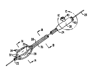
Referring to Fig. 1, the intravascular drug delivery c~lhe~r of the ~l~ sWlt
20 invention int~ ies an elong~t~ flexible shaft 20 having a distal end 2~ and a l,lo~
end 24. A movable guide wire 26 çyt~nrls through the c~th~tPr and beyond its distal
end 22. An eXp~ncion member 28 is ~tt~h~ci to the c~th~t~r shaft 20 near distal end
22. An irlfilci~m array 30 comrricing delivery con-lllitc 32 and orifices 34 is disposed
about the exterior sllrf~re of e~ ;on m~.ml~er 28. Cond-~itc 32 are in cu...~ tion
with delivery p~c~Ees 36 in c~sh~ter shaft 20. A h~lcing 38 is mollnt~l to ~ro~
end 24 of catheter shaft 20. ~o~cing 38 in~ es an agent introduction port 40 and an
infl~tion fluid intro~uction port 42.
A distal portion of the c~theter will now be described with reference to
Figs. lA and lE. A guidewire p~CC~ge 44 is disposed cen~rally in shaft core 46,
through wnich guidewire 26 is slidably disposed. F.xp~nci~ll member 28 s-l~.ounds
shaft core 46, with delivery co~ itc 32 disposed about its ~)c.;~hc.y Delivery
WO 94/09845 ~ 68~ 7 Pcr/us93/09454
il
conri~litc 32 incl~lde an axial pAC~ge 50 in commllnirA*on with orifires 34. Distal ends
33 of delivery cond~litc 32 are sealed. In a preferred embo~liment delivery collrh-itc 32
and ex~Ancion member 28 comprise a single integ~AtP~, monolithic extrusion, with the
delivery conduitc forming lnngitllrlin~l pAcc~ges in the wall of the e~A..~;on ,..~...1~. ,.
S It will be understood that the cAth~ t~r of the p~senl inven*on may have
any of a varie~y of guidewire co~fig~ *r)rls. For example, as shown in Figs. 7, 7A
and 7B, rather than being licrose(l cçntr-lly in the shaft core, guidewire pAcsAg~ 244
may be offset from the center axis in-lç~e.~c..l of and PA~1lP1 to inflAtirn lumen 54.
Moreover, such a guidewire pAcsAge need not extend through the entire length of shaft
20, but may instead have a lateral opening 245 at a point aiong shaft 20 through which
guidewire 26 exits the offset guidewire p~Cs~ge 244 and shaft 20, such that guidewire
26 and shaft 20 are indepenr~ent of each other at the plo~ al end of the device. Such
an offset guidewire is riescrihed in U.S. Patent No. 4,748,982, the comrlrtP r~icrlocllre
of which is incol~uldlcd herein by lefere.lce. I~LI1lhP ~ ...ore, a fixed guidewire (not
15 shown) extPnrling from distal end æ may be used in lieu of movable guidewire 26.
As illnstr~trd in Figs. 2A-2C, delivery con~ itc 32 may be integr~tPA
with e~l~A~ ;on memher 28 at various pocitinns relative to e-Ytçnor surface 48. In the
embo~iimPnt of Fig. 2A, delivery cQn~]~ C 32 are disposed e~tP ior to surface 48 so as
to protrude lhcfcr,u-ll. In the embo~ .t of Fig. 2B, delivery con~ it.c 32 are
20 disposed plill~ily in the interior of e~l~A~tC;on ~llel.lbcr 28 with orifices 34 eY~ nrl;.,g
through the ~hirl~ness of the çxrAncion member, such that surface 48 has a :~ib:~lAIll;Ally
smooth contour about the lJ~ el ~ of the e~ ;nn .-- ..bef. Fig. 2C shows Anothçrembo.1imPnt whel~in delivery conduits 32 are dicpos~pd centr~lly in the wall of
exrAncion ...e-..l,cr 28, producing only a slight ~ro~ e~,ce on surface 48.
The ~ her of delivery con~ it-c 32 may vary from one to eight or more,
but in a ~r~ d emborlimP-nt, there will be four delivery con~--itC spaced at
a~rox;...~t~ly 9o degrees about the circumference of e~ nC;or member 28. Delivery
con~-itc 32 may be disposed in various ~ nge.... -l~ about the ~ he.y of ex~A~;on
memher 28, both sy.~.~..Pl~ ;CA11Y and a~y...~ Ally. For example, the delivery
30 con~itC may be arranged such that a majority or all of the con~--its are on one side of
the ex~A.~cion member. Or, the delivery col-du;~ may be A~nged with two pairs ofclosely-spaced conrlnitc on opposing sides of eXpAQcion member 28. Moreover, the
W094/09845 ~ 6~57 12 Pcr/uss3io94s4
delivery co~A-.itc may be of different Ai~mPters, and may have varying sizes, shapes
and ~rr~nge~ of orifices 34. Orifices 34 may be in a single row, but may also bein a non-linear arrangement, or in multiple rows or groups on each delivery conduit.
Delivery conduits 32 will preferably have sufficient rigidity in the
S transverse direction so as to remain l-ncoll~rs~P~ when pocition-P,d by exr~ncion member
28 against a wall of artery.
Delivery con~l--itc 32 and orifi~^~es 34 will preferably be co~fig1~red to
infuse an agent at s--fficiP-nt plGS~ul~ to pC-~Ul~t'~- into the adventitial layer of the organ
wall. Usually, the device will achieve ~ PI. .I;on to at least the media. P~s~ures of
at least 4 ~tmos~llfrG5 are generally necec~y to achieve such yel-PL~ation. The preSGIlt
invention, in an exemplary emboAimPrt, will infuse the agent at a ~leS~ , of up to l0
atrnos~heres or more. This will be acsomplished by delivering the agent under
pressure from the ~roxilllal end of the catheter through delivery p~C~ges 36. Inaddition, the geometry and m~teri~l of the delivery conA~litc 32 will be s~lecteA to
f~rilit~tç ~cnP~ e infusion. In a ~lefeiled embo(limpnt~ the delivery cond,li~ 32 will
be co--,~osed of polyester, with an intprior ~ tel of about 0.1-0.2 mrn, and a wall
thirlrnPsc of about 0.05-0.l0 mm. Orifices 34 will have a Ai~ f te~ in the range of 10
to 50 ,um.
Referring now to Fig. lB, c~thPter shaft 20 ~lo"i,.,al to exp~ncior~
n,e."ber 28 inçlllAe5 shaft core 46 with guidewire 26 extenAing through guidewire
p~ P. 44. An outer body 52 of ~ne c~li,rler shaft ~ lo~mds an infl~*~ln p~c~ge 54.
Delivery p~Cs~es 36 and outer body 52, in a l,ler~ ,d embo~ t, comprise a
monolithic extrusion, with a variety of possible config~ tionc. In the embodiment of
Fig. lB, the delivery conAnitc 36 are disposed on the eYt~rior surface 56 of outer body
52. Other possible config~ tiQnc will be similar to those ilTI~st~teA in Figs. 2B and
2C and described above in connec~2on with delivery conduits 32. Further embo l;", --lc
are shown in Figs. 4A-4E and Fig. 5, descrihed more fully below.
F~tp~ncinn mPmher 28 may be adhesively ~tt~rhed to c~thete- shaft 20,
but will preferably be formed as a single extrusion, along with delivery p~cs~ges 36
and delivery conduits 32, forming a contin~lollc~ monQIithic structure from p~oxi~
end 24 to distal end 22. While known c~thrter f~hrir~h~n tecl~ ues have been used
to forrn a baUoon at the distal end of a tubular shaft, it is her~ toÇo.~ unknown to form a
WO 94/09845 13 ~ ~ ~ 68S 7 PCr/US93/09454
balloon at the distal end of a monolithic extruded structure with delivery conduits
wit'nin tne wall of the balloon and delivery p~Cc~gec within the wall of the shaft ir.
col...--.-.-it~*on with the delivery conr~nitc
Referring now to Figs. lC and lD, housing 38 in~ln~es an ~nmll~r
S rnanifold 58 in co.. ;~*on with a p~Cc~ge 60 t'nrough agent intro-l.. c*on port 40.
Distribution p~c~gPs 62 e~tend distally from manifold 58 to c~thPter body 20, where
they connect to delivery p~Cs~ges 36. Infla*on p~e~ge 54 extPn~C through hollcing 38
and connectc to p~c~ge 64 in infl~*nn port 42. Shaft core 46 is disposed within
inflation p~Cc~ge 54, with guidewire 26 e~t~n~ing through guidewire p~Cs~ge 44.
A further embodiment of the c~thP,ter of the ~r~se.ll invention is
illustrated in Figs. 3A-3C. In this embo~iment housing 38 at the ylo~ulllal end of the
device has a plurality of agent introduction ports 140, each introduction port being in
comm--ni~tion witn one of deliver,v p~c~ges 36 in c~thetPr shaft 20 via connPction
passages 162. In other respects, the c~thPtPr is much like that described above in
15 cormection with Figs. lA-lE, except that delivery p~Cc~ges 36 and delivery con~ itc 32
(not visible) have the configuration illllstr~tpd in Figs. 2B and 3~, respectively.
By providing Se~ d~e intro~ction ports 140 for each delivery p~Cc~ge 36
and delivery conduit 32, the invention as embodied in Figs. 3A-3C ~ell,.i~ direction~l
infusion of one or more agents through orifices 34 in different delivery conduits 32 of
20 infilsion array 30. This may be advantageous where only a particular portion of a
vessel is to be treated, and in~l~ion to other portions is l~nr~ir~hle. Direction~l
infusion may further be useful to infuse a first agent through one or more delivery
conduits 32 at sel~c~d directions, while ciml~lt~nPously infi~cing one or more other
IhP~ agents through other delivery COn1~I;I`; In this way, for example, a growth-
25 inhibiting agent may be delivered to a stenodc region of the vessel through the delivery
Oco~ on one side of the c~thet~r, while an anti-co~glll~nt is delivered through the
delivery conduits on another side of the c~thPter.
A further embo~imPnt of the c~thPtPr of the ~Sell~ invention, illllst~tpll
in Figs. 4A-4E, comprises a se~dte ~ t~tion c~thPt~r 70 of conventinn~l construction
30 removably disposed in an axial passage 72 in catheter body 20. An exp~nd~ble support
member 74 is ~tt~çhP,I to the distal end of c~thPtPr body 20, more clearly illllctr~tpd L'l
Figs. 4C and 4E. Support member 74 compri~S a tubular structure having a plurality
, 2 1 ~ 14 Pcr/uss3/o94s4
of separate support sections 75. Delivery conduits 32 are disposed on a lateral surface
of support sections 75, and are in co,.~ ic~tion with delivery passages 36 in c~thPter
body 20. Orifices 34 are disposed on a lateral surface of delivery conduits 32, with
distal ends 33 of delivery conduits 32 sealed. While support member 74 and delivery
5 conduits 32 are shown as separate structures mounted to c~thPter body 20, it will be
understood that catheter body 20, SuyyOl~ member 74 and delivery co.,duils 32 may
comprise a single (monolithic) extrusion, as described above in connection with Figs.
lA-lE.
Removable rlil~t~tion catheter 70 is slidably disposed in axial passage 72
10 in c~thPtPr body 20. The f~ t~tion c~thPter 70 will be of conventional construction,
and inrllldes a guidewire passage 76 in a core 80 as shown in Fig. 4D, through which
guidewire 26 is slidably inserted. An outer casing 82 surrounds core 80, defining an
inflation passage 78. An expansion member 84 is formed from, or adhesively mounted
to the distal end of casing 82, and is sealed at distal end 22 about core 80. When
~ t~tion catheter 70 is positionp~ in c~thPtPr body 20, exr~n~iQn member 84 resides
within interior lumen 86 of support mPmber 74. Guidewire 26 and/or core member 80
extend distally hrough a distal opening 88 in Suy~ulL mpmber 74.
Support member 74 will be constructed of a ll,atelial similar to that of
exr~n~inn l~,ember 84 so as to expand Lher~wiLh. When e~ ion member 84 is
20 infl~tPd, as shown in Figs. 4B and 4C, support section~ 75 are distended and se~ d
as uhey expand oulw~u~d with the e~ n~ion member.
A further ~lt~prn~tive embo~impnt of the c~thPt~r of the yl~selll invention
is ill--ctratP~ in Fig. 5. In this embo.limP-nt the c~thPtPr comprises a plurality of
delivery conduits 90 e~rt~Pr1(ling from the distal end 22 over exl-~ ;on member 28 to the
~o~ lal end (not shown) of c~t~.et~r shaft 20. Delivery conduits 9G have orifices 34
on a lateral surf~ce thereof oyyOSik; e~cr~nd~hle ~I.ellll)er 28. Delivery c~n-~litC 90
be f~c~Pned at distal end 22 and to the extpric)r of e~th~PtPr shaft 20, but will be
nn~tt~ Pd tû e~Yp~ncion nl~lllber 28. This ln~lllU~:i delivery conduits 90 to be ~lisp~ d
as exp~n~iQn member 28 is infl~tPd, without creating stress concPntrations on the
30 surface of expansion member 28 as might be created by direct ~ chmPnt of the
cûn~uil~ thereto. Fur~ermore, e~ ion member 28 may be compliant. ~'~thPt~r
shaft 20 and exp~ncion member 28 will otherwise be subst~nti~lly si~rilar to those of
W094/09845 5 ~ ?1~68~7 Pcr/us93/o94s4
Figs lA-lE or 3A-3C. Delivery co~ itc 90 may be manifolded at the ~ro~ lal end of
the c~thPt~ as in the emboriim~P~t of Figs. lA-lE, or conn~ct~d to separate agent
introrluction ports as in Figs. 3A-3C for direction~l infusion. The invention asembodied in Fig. S p;ovides a c~theter of very simple, low-cost COI.sL,.lction with
5 indepe~ient infusion and exl,~n~ior- as well as direction~l infi-cion c~r~biliti~os.
Figure 6 illustrates a further embo~iim~nt of the c~theter of the pl~ se.lt
invention. The e~tl.e~er inclllAes a body 20 having an e~ .C;on memher 28 near its
distal end 22, a guidewire lumen 44 ~ f..~ through the body 20, and a pl~lrality of
delivery p~c~ges 36 integrated with body 20 in a lorlgih-riin~l di~e~oll. In this
10 embo iim~nt, a ~ro~....al infilcion array 30a is disposed on the e;~ shaft lJio~i,llal
to expansion member 28, while a distal infusion array 30b is disposed on the c~ll.el~r
shaft distally of exp~ncion member 28. ~nfi)cion arrays 30a, 30b incl~de a plurality of
orifi~es 34 disposed on a lateral surface of delivery con~llitc 32, which are in fluid
connP-ction with delivery p~Cs~ges 36. Distal portion of c~th~t~ body 20 distally of
lS eYp~n.cin~ e~ er 28 may be of reduced ,i;,.. t~-~ to f~-ilit~tP po~i*nning in a vessel.
In this emboriimpnt~ the c ~t~.~ter of the ~l~sel-~ invention facilit~tPs riil~t~tion using
eYp~ncion me,llber 28, while i..r-~;..g an agent through infilsion arrays 30a, 30b.
~nfi~cion may be pt:lroll.,ed inriepen~ently of riil~t~tion, pe~ ;.lg infilsiol~ of the agent
before, during, after, or without riil~t~ti~m. rul~ r, as in other embo~ -f -l~, each
20 delivery p~Cc~ge 36 and delivery condllit 32 col~ -ation is in~lependent of each other,
so as to f~ilit~tP direction~l inî~Cior and/or inf~l~iolt of two or more dirre~ t agents
cimlllt~nPo~lcly. It is also understood that the c~thpt~r may inr~ le only one of either
distal infusion array 30b or ~iu.~i."al infilc~ array 30a, and that orifi~s 34 may be
in~lllded only on selçcted ones of delivery con~ tc 32. rulther, the c~ f may
25 cornpric~ in ~d~iition to infil~iorl arrays 30a and/or 30b, asl infilsion array about the
periphery of the e~p~ncion mPmher in the ...~ r descrihe~ above with lefe.~ nce to
Figs. 1-3.
~thPters constructed in accolda.lce with the prinrirles of the pn senl
invention may optionally be modifiP(l to provide for perfusion or by-pass blood flow, as
generally described in U.S. Patent Nos. 4,661,094, and 4,892,519, the disclosures of
which are incol~t.,dL~d herein by reference. (~enpr~lly~ such per{i~cinn flow can be
provided by one or a series of perfusion ports on tlle ~ro~ lal side of the ex~ ;on
Wo 94/09845 ~ 6 8 5 7 Pcr/US9~/09454
16 ~
member 28, which ports permit the flow of blood into the shaft core 46 and eventually
out through the distal opening of said core. In this way, blood flow can be m~int~in
even when the e~p~n~ n member 28 is exr~ndçd and would (in the absence of the
perfusion capability) block blood flow.
S It should be understood that the catneter of the l~lese,-t invention is
suitable for delivery of a variety of thelayc;.lLic agents inclll~ing ph~rrn~rentir~lc~
proteins, peptides, nucleotides, carbohydrates, poly~rrh~rides, muccopoly.c~rch~ri~es,
sirnple sugars, glyco~.~ oglycans and steroids. The yl~se.-t invention f~cilit~tes
delivery of such agents in a variety of forml~l~tio~c, inrlll~ing aqueous vehicle or
liposome. The drug delivery catheter is furtner useful for delivery of viral particles to
f~cilit~tP gene transfer. The agents delivered may ~t~roill. a variety of fi-nrtio~c,
inrl~lding a~ uo-l~botics antiplatelets, ~n*met~holics, growth factor inhibitors, growth
promoters, ~ntiro~ulants~ ~ntimitotics~ and antibio~ics.
In a further embo-limPnt, illnctr~t~d in Figs. 9-17, the agent infusion
catheter is configured to slidably receive a conventinn~ t~tion c~ll.ft l within an
axial guide p~c~ge in the infusion c~thPtçr shaft. This allows the ~ t~tiQll C5~11.f ~l t to
serve as a guide wire for the infilcion c~thPter to guide the r~thçtPr to the Ll- ~I.,.P-~
site, f~rilit~t~s ~ t~ti~ln of a s~notic vessel indepe~ld~ntly of agent infilcion, and
~lll~i~ the use of any of a variety of commercially-available r~ t~tiQn c~thPter~ in
conjnnrtion with the agent infusion c~th~tPr of ~e invention. Dilatation r~thPters
suitable for use with the infilcion c~thPt~r illllssr~t~d in Figs. 9-17 are clescrihe~, for
eY~mrlP, in U.S. Patent No. 5,041,089, U.S. Patent No. 4,323,071, U.S. Patent No.
4,292,974, U.S. Patent No. 4,762,129 and U.S. Patent No. 4,775,371, the coi~.r'~P
dicclosl~res of which are incorporated herein by reference. Such ~ t:ltion c~itl~e~ ;~ are
co~ elc;ally available from, for exarnple, Advanced Cardiovascular Systems, LnC., of
Santa Clara, California.
Referring to Fig. 9, in a preferred embo~imPnt agent infusion c~thPt~Pr
200 in~ludes an elo~gate flexible shaft 202 having a distal end 204 and a ~ uual end
206. A manifold assembly 20% is fLxed to the ~lu~ llal end of the shaft and inr~ ie~
~ t~tion catheter port 210 on i~ plo~il"al end and an agent introduction port 212 in a
fitting 214 provided with a Luer lock (not shown), securecl to the ~scemhly. At the
distal end of the shaft 202 is an inf~lcion array 216 having a plurality of orifices 218
W O 94/09845 ~ 6 8 PC~r/US93/09454
along lateral surfaces of the shaft. Shaft 202 comprises a plurality of axially disposed
agent delivery passages 220 extending from the ~loximal end which are connloc~d to a
corresponding number of agent delivery conduits 222 at the distal end. Orifices 218
- are in communication with interior axial lumens 233 in delivery conduits 222. An axial
S cut or slot 224 is formed in shaft 202 between each of delivery conduits 222 such that
the delivery conduits are separated from one another by the slots. A stiffening element
226 is disposed in at least a single delivery conduit 222, as described more fully below.
A conically tapered distal tip 228 is fixed to the distal end 204 of the shaft.
In a preferred embodiment, shaft 202 will be constructed of materials and
will have dimensions selected as al)pro~.iate for insertion of the shaft tr~n.cll~min~lly
inside a guiding catheter (not shown), in a blood vessel. In an exemplary embodiment,
shaft 202 will have a length in the range of 110 to 150cm, and an outer dian~eler of
l.lmm-2.3mm (0.04 to 0.09 inches). Infusion array 216 will be approximately 10 to
60 mm in length. C~th~ter shaft 202 may be any of a variety of biocompatible, flexible
materials inclllding, for exarnple, polyester, polyethylene or polyamide. Preferably, as
described above, catheter shaft 202 (inr.l~lr~ing delivery p~ es 220) and delivery
conduits 222 will comprise a single, monolithic extrusion from proximal end 206 to
distal end 204.
As shown in Fig. 10A, in an undeployed configuration, infusion array
216 is ~ligne~l with and has an outer diameter generally equal to that of the proximal
portion of shaft 202. As shown in Fig. 10B, a dilatation catheter 230 may be
positioned through an axial guide passage of shaft 202 (described below) such that a
balloon or other expansion member 232 at the distal end of the t~ t~tion ca~,e~r is
within infusion array 216 ~dj~cent delivery condllit~ 2æ. By e~cp~n.ling balloon 232,
infusion array 216 is deployed radially outward to bring orifices 218 ~dj~cent to a
treatment site on a vessel wall.
Fig. 11 illustrates a transverse cross-section through a ~,roxin.al portion
of shaft 202. A guide p~s~e 234 extends longihldin~lly through the catheter sllaft for
slidably receiving a dilatation catheter. Guide p~ge 234 may be coated with a
lubricious material such as a hydrogel or fluorocarbon polymer, for example,
fluorinated ethylene-propylene or polytetrafluoroethylene, available co,l"~ercially under
the trademark Teflon0 from DuPont. Such a coating facilitates longihltlin~l positioning
WO 94/0984~ 4~8 5 7 18 PCr/US93/094~4
and ~lignment of a ~ t~fion catheter in guide p~ge 234 when catheter 200 is
disposed in a tortuous configuration in a vessel. Guide passage 234 will have a
di~ ter of 0.7-2.0mm (0.03-0.08 inches), preferably 1.2-1.8mm (0.05-0.07 inches),
suitable for receiving most commercially-available dilatation c~th~ters in current use.
S Delivery p~ges æo run parallel to guide pa~ge 234. In an
exemplary embodiment, delivery passages 220 are disposed in longih.~lin~l ribs 236
which protrude radially outward from shaft 202. Delivery passages 220 will have an
interior height (or ~ meter, if round) in the range of O.Olmm to 0.7mm (~0.005-0.03
inches).
Figs. 12A-12E illustrate transverse cross-sections of the distal portion of
shaft 202 through infusion array 216 in various embor~iment~. In the embodiment of
Fig. 12A, delivery conduits 222 are separated from each other by slots 224 so as to
permit lateral expansion for deployment of the delivery conduits. Delivery conduits
222 have an axial lumen 238 which is in comml-ni~tion with delivery passages 220 in
the catheter shaft. Delivery conduits 222 surround guide passage 234. Stiffeningelements 226 are disposed within axial lumen 238 and occupy only a portion thereof to
permit flow of agent through the lumen. In the embodiment of Fig. 12A, stiffenerelements 226 comprise ribbon or bar-shaped rods of generally rect~ng~ r cross-
section. The rods may be unrestr~ined in the axial lumens of the delivery conduits,
secured at their distal end to the distal tip as described below, or co-extruded in the
walls of the delivery conduits, also described below. Stiffener elements 226 may be
any of a variety of materials such as st~inl~s~ steel, t~nt~lllm, nickel-tit~nillm, or
tungsten and having a geometrical configuration leading to greater axial rigidity but
being latelally more flexible and resilient. The stiffetling elements may extend from
distal end 204 to proxirnal end 206 of shaft 202 through the delivery p~ges, or may
have a shorter length, e.g. 30-70 mm, so as to extend from a point near distal end 204
to a point just proximal to infusion array 216.
Stiffener elements 226 serve several functions. First, the stiffener
elements help to m~int~in the patency of axial lumens 238 in ~e delivery conduits.
Second, ~lirr~l.e,- elements 226 provide stiffness and resilience to delivery conduits 222
such that, following expansion of the delivery conduits, ~ey will recoil back to the
undeployed configuration. Third, stiffener elements 226 serve to m~int~in the relative
WO 94/09845 1~ ~S7
gnment be ween the delivery conduits during longitn~in~l positioning and later
exr~ncion, so that the delivery conduits remain a~lo~din~ately equally se~dld~d from
each other when deployed, f~cilit~ting uniforrn tre~tment of an area of the vessel wall.
I~ul~lellllore, a stiff~on~r el~ment 226 of rect~ngnl~r cross-section allows controlling the
S relative m~gnitnde of lateral versus radial stiffnPss. In the confi~l~r~tion shown, the
ben-ling stiffnPcs of stiffener elpmpnt 226 is subst~nti~l1y less in the radial direction
about a first axis perpenrlic~ r to the shaft than in the lateral direction about a second
axis perpen~icnl~r to the shaft and ~el~en~licl~l~r to the first axis.
Fig. 12B illnctr~tes a further embo~iim~nt of delivery con~l-itc 222 and
s~;rr~,-;.. g elPmPntc 2~6. In this embodimp~nt~ slot 224 is cignifi~ntly wider than in
previous embo-1imPntc, such that sl~kst~nti~lly all of the m~tPri~l between delivery
conduits 222 is removed. Further, in this embo~im~nt, stiffçner elementc 226 comprise
rods having a round cross-section With such a shape, the stiffen~r ele...f-.-lc are
particularly effective in ~ lt~ g the patency of axial lumen 238. Further, the
15 stiffener elemPntc of round cross-section will not tend to block p~Cc~ge of an agent
through orifices 218 if the rods float to the outer s~rf~te of the axia~ lumen.
In the embo-limP!nt of Fig. 12C, ~I;rLnpr ÇIP..~P.lllc 226 CQ-..p. ;.ce rods
round in cross-section embedded in the outer wall 240 of delivery cor-~nit 222. It
should be understood that sl;rr~ er el ... ~ of various cross-sect~nn~l shapes may be
20 embedded in the wall of the delivery cond~it~ in the ..I~".~er shown in Fig. 12C.
In the embo~iment of Fig. i2D, snTTen~r elelnPnt~ 226 are disposed
exterior to delivery con~itc 222. In an exernr!~ry embo~imPnt, the s~;rre..~l elomentc
are disposed along a side sl..f~ce of each delivery condl~it so as not to i.~t~. re~e with
cont~rt between the outer lateral surfaces of the delivery conrh~itc and the wall of the
25 vesseL Again, s~;rr~ ek- .lf ~lc of various corfigl~r~tiorlc may be used, inrhl(ling
round, rect~ng~ r, and other cross-sectinn~l shapes.
In Fig. 12E, several additional embo~imentc of sl;rre~-er el~ tc 226 are
illustrated. In these embo~i...e -t~, the stiff~oner elPrnPntC have a surface contour which
prevents the stiffer-er el~mPntc from blocking flow of agent through orifices 218 should
30 the stiffener elemPntc float outward against the outer wall of the axial lumen. In one
embo liment7 slirræl~er el~PnlPnt 226a has a zig-zag cross-sectinn. In a second
embo~imPnt ~I;rr~ .~Pr element 226b has a double curve or wave cross-section. In a
WO 94/09845 2 1 ~ 6 g ~ 7 Pcr/uss~/o94s4
20 ~--
third embo~iimpnt~ stiffener element 226c has a longihl~in~l ridge 242. In theseemb~imP-ntc, a plurality of transverse slots (not shown) may be provided at various
points along the length of the stiffenPr elPmPntc to reduce radial stiffnPsc and enh~nce
the free flow of agent from one side of the stiffenPr elPment to the other.
S In another exemplary embo~limpnt~ illllstr~tPd in Fig. 12F, 7l;rræ-~-Fr
elPmPntc 226 will have a plurality of cut-outs 227 along their length, which may take
the form of inrlent~tions along the longitlldin~l edges as shown, or, ~ltern~tively, slots
or holes through a middle portion of the ,I;rre ~Pr elPmPntc. Cut ou~, 227 f~t`ilit~tP
flow of agent from one side of the stiffener elemPntc to the other to ensure the agent is
not blocked from flowing ~hrough orifices 218.
In a further emboriim~nt of infusion array 216, illustrated in Figs. 13 and
14A, an elActnrnPric sleeve 248 is mounted in guide p~Cc~ge 234, with delivery
cond~-its 222 disposed about the l~el;phery of the ela7lo-l-e,;c sleeve. Fl~lo~le~;c
sleeve 248 will comprise a tubular ehPmP-nt of a flexible and resiliPnt el~lo..-elic
15 polymer, such as silicon or Ul~ th~h~e. Usually, delivery con~ tc 222 will be fixed to
the exterior of el~c~o.--P,;c sleeve 248. In this way, the el~(o,..f ~ic sleeve serves to
f~ilit~t~ resilient return of t'ne delivery contlllitc from tne deployed to tne lndeployed
poCition. In ~rlriition7 t7ne Pl~ctorneriC sleeve serves to ....;..~ ligllll.P.~t of the
delivery conduits as tney are exp~nded so as to m~intAin proper spA-ring between~ acçnt delivery con~itc. W7nile stiffenPr elpmpntc 226 are inrlllded in Figs. 13 and
i4, the use of elasLul"e"c sleeve 248 may obviate t7ne need for ,I;rL -;..g eie ..P~ , as
the sleeve may adequately IllA~ Aliglllllf~t and provide resiliP~re.
In an alternative embo~limpnt~ ls~tPd in Fig. 14B, el~c~o...~.ic sleeve
248 is disposed ~torn~l to delivery confi~itc æ2, with the delivery cor-d~.itc secured to
the interior of the sleeve. Orifices 218 extend from axial lumen 238 through delivery
con~ itc 2æ as well as through el~ . ;c sleeve 248. ln a preferred embo-lim~rt
the el~ctompric sleeve is co~figl-red so as to ~en~r~lly conform to the exterior contuLIr
of the delivery conduits, ~ g the profile of the distal portion of the catheter, as
well as accommori~ting the expansion of the delivery conduits.
Referring now to Figs. lSA-lSC, distal tip 228 will be more fully
described. Distal tip 228 provides a ",;.~ lly tr~--m~tiC leading edge to catheter 200,
as well as f~rilit~tps slidable tracking of c~thetPr 200 over a r~ t~tion c~thPtPr, as
WO94/09845 2~ 8S7
described more fully below. In addition, the distal tip 228 provides a seal for the distal
ends of delivery conduits 222. In an e~empl~ry embodiment, shown ir. Figs. lSA-15B,
distal tip 228 has an axial passage 250 ~lignP~d with guide passage 234 in shaft 202.
Distal tip 228 has a conically tapered exterior to enh~nre navigation of the c~thPter
S through a vessel lumen. Usually, distal tip 228 will have a length of 1 to 5mm and
rinr ~ lP~I at ~ ;al end 254 genlor~lly equal to that of the outer s--rf~r,e of the
delivery co.-d.-;t~ 222, with distal end 252 being a~plox;.~.~tP-ly 30% smaller in
~-~---r~r than lJru~Ll..al end 254. Distal tip 228 further inr~ es a pl-~ y of
~f~ lly-extPn~ing prongs 260, which fit within axial lumens 238 at the distal ends
of delivery conduits 222. Prongs 260 thereby provide a seal for the distal end of the
delivery conduits and provide the ~h~sio~ to shaft 202 required to plope,ly retain
distal tip 228 with the catheter. Prongs 260 can also be employed to retain the distal
ends of ~I;fre~.çr elPment~ 226 within axial lumens 238. In one embo-iim~ont~ distal tip
228 may be mol~e~i urethane, formed by a process in which urethane is poured into a
15 mold and the distal end of shaft 202 is inserted into the mold while the ~ ha..c is
liquid, ~cllllilLing the ~lleth~le to wick into axial lumens 238, thereby forming prongs
260.
In an ~lt~ tive embo.1im~nt of the distal tip, illustrated in Fig. lSC,
distal tip 228 has a trumpet shape wh~,leill axial p~cc~ge 250 tapers radially outward in
20 the distal direction. The outer yel;~kel~ of dist~l tip 228 may be tal,el~d inward near
the distal end 252 to f~cilit~t~- navigation through a vessel lumen. The L..~ et-shaped
distal tip of Fig. lSC f~ilit~tt~s smooth retraction of the e~p~ncion ll.eillber (e.g.
balloon) of a dilatation c~rh~ter from a position distal to distal tip 228 to a position
within guide p~cs~gç 234 ~ cent delivery con~litc 222.
Fig. l5C further illl-s~tes the retention of distal ends 229 of stiffçn~r
cle ..~ c 226 by enc~rsul~tirJn in prongs 260 of the distal tip. In this embo~limPnt,
when distal tip 228 is to be formed, ~l;rr~.~Pr elem~ntc 226 are pocitione~i in axial
lllmPnc 238 of the delivery cQn~lllitc with distal ends Z29 near the distal end 204 of
shaft 202. Distai tip 228 is then formed as described above, by pouring a polymer
30 such as urethane into a mold and putting the distal end of the c~th~tPr shaft in the mold
while the ulc;tll~ule is liquid. The urethane then wicks into axial lnm~onc 234,e~r~rsul~ting the distal ends of the stiffen~r elPm~n~c.
WO 94/09845 '2 1 4 ~ 8 5~ 22 PCr/US93/09454
Referring now to Fig. 16, manifold assembly 208 will be more fully
descnbe~. The manifold assembly in~ des a housing 262 which may be a metal or
any of a variety of rigid plastics, in~ riing acrylonitrile-bllt~ np-styrene (ABS),
Delrin~, polycarbonate and the like. Shaft 202 ext~n-ls through a flexible polymeric
S strain relief 264 into an imerior chamber 266 witnin ho~lcing 262. The ~lo~ ,al end
270 of s'naft 202 is secured about a cylinrlrir~l mandrel 272 formed in hollcing 262.
Mandrel 272 has an axial bore 274 which conn~ctic ~ t~tirJn c~th~t~-r port 210 to guide
p~cc~ge 234. In a preferred embo-iim~nt, a diaphragm 275 is mollnt~d in a pro~ al
portion of bore 274 near catheter port 210. Diaphragm 275 has a p~Cc~ge 277 which
may comFIri~ a hole or slit which el~ctir~lly exp~nric when a ~ t~tior~ c~th~ter of
larger ~i~...eler is inserted through it. The diaphragm thus provides a sealed entrance
for introducing a riil~t~tion c~tht~r into guide passage 234.
Ch~llber 266 is in co~ tion with agent intro~uction port 212 in
Luer fitting 214. The pr~ ,al end of shaft 202 will have circumfelc.l~ial notches 268
providing fluid co.. ir~tion between chamber 266 and agent delivery p~cc~ges 220.
Luer fitting 214 will be configured for conn~c~on to a precision agent delivery device.
In this way, an agent delivered through delivery port 212 will flow into delivery
p~C~ges 220 for delivery to infusion array 216.
In a preferred embo~lim~r t of the method of the l.~esenL invention,
20 i~ str~ted in Figs. 8A and 8B, the c~th~t~r is posi~ionPd tr~ncl--min~lly in a body lumen
or vessel V, which will typically be an artery. 'l'he vessel will have a wall comprising
three layers, int~ln(ling intima I, media M and adventitia A. The c~th~t~r will be
position~d such that orifices 34 in delivery conduits 32 are disposed near the L~
site, which will most often be an atherosclerot~c region of st~nocic S in the artery.
25 Usually, a movable guide wire 26 will be used to guide the c~th~tçr through the artery.
A fixed guidewire ~tt~ch~od to the distal end 22 of the calhe~r may be used inct~d.
When the catheter has been positioned near the l~e~t.-.ent site S, the
exr~n~inn m~mher 28 is infl~t~c~ with an inflation fluid introduced through inflation
fluid introduction port 42 in housing 38 at the pro~ al end of the c~th~tPr.
30 Preferably, e~cr~n~ion member 28 is e~cp~n~ed s--ffici~ntly to bring delivery conr~it~ 32
into contact with the t~e~tm~-nt site S. If desired, ~ t~tion of the vessel may be
~lrull,led by infl~ting e~r~n~ion member 28 sufficiently to expand the interior of the
WO 94/09845 ~ 6 PCr/uSs3/09454
vessel lumen in the region of stenosis so as to effectively restore blood flow to an
appru~iate level.
Frequently, it will be desirable to impregnate the tre~tmPnt site S with an
agent before, during or after such ~ t~*on. Advantageously, the physician may
S position the de}ivery conduiLs 32 against the tre~tmPnt site and l c-ro~ll. any desired
t~tion wi~hout infilcing any agent through o~ifices 34 in conduits 32. When agent
delivery is desired, an agent is introduced through agent introductirn port 40 in
~ro~ al honcing 38, from which it is co.. ~.. ir~tPd through delivery p~cc~gPs 36 to
delivery conduits 32. The agent will be infused through orifices 34 to lJ~nellnte the
0 ~ t site S. Usually, the agent will be infilcPd into the l.e~ site at pressures
sufficiPnt to attain per-Pt~tion to at least the media M, and preferably into the
adventitia A of the vessel.
In an ~ltprn~tive mPthod, an agent may be infilced into the lumen before
eYp~n(iing the e~p~ncicn member. After infilsion, or while it is col.~ ;..g, an infl~*on
15 fluid may be introduced into the device to exr~n~ the ex~ ;on member, pocitionin~
the delivery con~l~-itc adjacent the lumen wall. Infusion of the agent may col.l;..ue, or a
dir~rellt agent may be infilsed through the delivery cond~-itc to ~)enelldte a L-~t~..e-
~site within the lumen wall.
In a sperific embo~imPnt, the mPtho~l may comprice infilcinp an agent
20 tnrough one or more selP-cted delivery condnitc 32 without infilcing the agent through
other sPl~cted delivery con-l--itc. Using the c~thPter illustrated in Figs. 3A-3C, the
agent will be introduced th~rough one or more agent introduction ports 140 c~ to
the delivery con~--itc 32 which are to be used for infilcion. For example, in Figs. 8A
and 8B, an agent may be infilser~ through delivery cond~itc 32a, 32b, but not through
25 delivery con(lnit 32c, by introd-~ring the agent through the col,~syonding introductiQn
ports 140 at the ~r~ llal end of the c ~ tr..
In a further embo-limPnt the m~thod may inr~ e infi~cing a first agent
through selPcted ones of delivery con~nitC 32 while infi~cing one or more different
agents through others of delivery cond--itc 32. Referring to Figs. 8A and 8B, a first
30 agent, such as a growth inhibitor, may be infilsed through delivery con~uit 32c, while
infilcing a second agen~, such as an anticoagulant, through delivery conduits 32a, 32b.
This is accomplished by introdll~ing the first agent through the ap~lopliate introduction
:2 ~ ~ 6 8 5 7 24 Pcr/uSs3/094s4
port 140 (Fig. 3A) co.-.-e.:lrd to cond~-itc 32a, 32b, while introduçing the second agent
through the intro~..ction port 140 connPcted to delivery conduit 32c.
Once tre~tmpnt at a particular site has been completed, drug delivery may
be t~ t~i, and, if desired, e~p~c;orl member 28 deflated by withdrawing the
S e~pancinn fluid through inflation passage 54. Dilatation and/or agent infusion may be
repeatPd at the 1~ site S. When tlc~ P ~l of the site is cornplete, the cz.tllPt~;r
may be repositinned without removing it from the body to ~elrul~ t~ti~n and/or
agent infusion at a new tre~tment site. It can be seen that the device and method of the
lJlcselll invention f~ilitat~ infusion of an agent with or without ~lilat~*on, ~ilat~tinn
10 with or without infusion, infusion of multiple agents cim~llt~nPollcly, direction~l
infusion, and tre~tTnent of multiple sites, without removing the device from the body
between such tre~trnPntc.
A further embodiment of the method of the invention is i~ ctratpd in
Figs. 17A-17D. In this embo-limPnt, utili7ing the agent infusion catheter 200 described
15 above in connPction with Figs. 9-16, a balloon rlilat~tion c~thPtPr DC of convelltio
construction is ~nclllmin~lly positionptl in a blood vessel V such that a balloon or
other eyr~nci~n ,..~ her 280 (in an ~...;..ll~d corlfi~-~*on) is near a ~e~l...e..~ site S.
Typically"lil~tatiQn c~l~.eter DC will be pocitionPd over a movable flexible guide wire
GW. During this step, agent infilcion c~thPt~Pr 200 need not be, but may be, positioned
20 slidably over ~ilatation c~ r DC. In some embo~limpnts~ it would be desirable to
position a niiat~tion cathpter in the vessel first, do a ~ t~tion and then remove the
t~tion c~tl.Ftr r. Subsequently, c~thPter 200 is introduced over the ~ t~tinrl C~ ,tf r
and both c~thPt~s are introduced together into the vessel. In other in~t~nces~ c~theter
200 will be pocitionPd over the ~ t~tion c~thetPr outside of the body, and both
25 c~thet~ls will be tranclnminally po-citio;-pd in the vessel together. The ~ t~tisn
c~thPter may then be used to pelrollll rlil~tation as ~esçrihed below.
As shown in Fig. 17B, balloon ~lilat~tiorl c~thet.~Pr DC is pocitioned such
that e~pancion mernber 280 is disposed distal to the distal end of agent infusion c~thPter
200. Flcp~ncion member 280 is then inflated using known techniques, ~ t:qting vessel
30 V at ~e~l-.-e~l site S.
F~Cp~ncion member 280 is then deflated ar.d, as shown in Fig. 17C,
dil~t~tion catheter DC is drawn proximaUy relative to agent infusion c~h~!~r 200.
WO94/09845 25 21~68~7
Dilatation cAth~ter DC is positio~d such that expansion member 280 is adjacent
inf~lcion array 216 in the interior guide p~cs~ge of c~theter 200, described above.
Agent inf(lsion catheter 200 is then positionPd within vessel V such that infilcion array
216 is near Llc~ -P-~ site S.
S FYpancir~n member 280 is then inflAt~d so as to position delivery con~1--itc
222 in ap~osiL,on to treAtm~nt site S on the vessel wall. An agent is then delivered
through delivery pAC~Ees 220 in catheter 200 to delivery contl~itC æ2. The agent is
infi~ under preSau~ through the delivery cond~litc and through orifi~ec 218 to
~nrl.~tt~ the vessel waU in the region of LI~A~ e"t site S. When lleAIl.~F ~t is complete
at the site, agent delivery is ~icco~tinlle~ and exp~ncion member 280 deflated to return
delivery cor(lllitc 222 to an undeployed position as in Fig. 17C. If further tre~trnent is
desired at the same or different site, dil~t~tinn catheter DC may be extender~ distal to
infusion c~theter 200 to the position shown in Fig. 17A. Dilatation and/or agentinfusion may be repeated at the same or a different site.
To f~cilit~te longitlldin~l positioning of infilcion catheter 200 in a vessel
lumen, as well as to assist proper axial ~lig.. P.. ~ of the e~p~ncion ,.. e.nbGr (e.g.
baUoon) of the ~ t~tinn c~thlot~r with inf~lcion array 216, radiopaque l.~LGl~ may be
provided on infusion c~thet~r 200. In a ~lc~Gl~d embodiment, shown in Figs. 18A-18C, radiopaque m~Lels 282 are disposed on one or more of stiffer er ek .~ 226.
20 ~rkPrs 282 are formed by, for example, plating a radiopa~ue m~t~l such as gold or
pl2~ onto stiff~nPr elpmpntc 226. Dil~t~tion c~th~ter DC wiU also have a
radiopa~ue marker 284, which is typically formed on the inner shaft 286 of c~thlot~r
DC in the interior of eYp~ncion el~nent 280. In one embo~iment shown in Fig. 18A,
at least two IlldlkGl:i 282 are disposed on ~I;I~..er elemtontc 226 in a central portion of
25 infi~cion array 216, the IlldlkGl~ being sep~r~t~?~ a rlict~nce from one another usually
about equal to or slightly greater than the length of marker 284 on ~ t~tion ç~thet~-r
DC. In this way, by vic~li7~*on through a radiographic im~ging device, Ill~ls 282
f~`ilit~t~ axial ~lignmPnt of expansion element 280 with infilciorl array 216 by ~ligning
t~*Qn catheter marker 284 between markers 282 on sLirre..el el~m.ontc æ6.
Markers 282 filrther provide visual in~ic~*on of the locahon of infusion c~thet~r 200
within the vessel so that infusion a~ay 216 may be poci*on~d adjacent to a ~ u.,.
site.
Wo 94/09845 2 1 4 ~ 8 ~ 7 PCr/US93/09454
26 O
Alternative embo~imPntc of radiopaque markers 282 are illn$tr~tPd in
Figs. 18B and 18C. In Fig. 18B, marker 282 is disposed on a distal portion of
stiffenPr e~PmPnt 226. In this way, r~ t~tion c~th~tPr DC and/or infllcion catheter 200
are axi~lly re-positioned relative to one another until marker 284 on the ~ t~tion
S r~thPter is exposed on the plo~unal side of marker 282. In the embo-iiment of Fig.
18C, marker 282 is disposed on a prox,lllal portion of stiffener elPrnPnt 226 wlleltl)y
the r~thPt~rs are axially aligned by positinning riil~t~tion catllt~r Ill~h~r 284 distal ~o
~h~;r 282 on the sl;r~ elPment
While the above is a complete description of the preferred emborli..,~l"~
10 of the invention, various ~ltPrn~tives, moflific~tinns, and equivalents may be used.
Therefore, the above description should not be taken as limiting the scope of the
invention which is ~efinP~ by the appended claims.