Note: Descriptions are shown in the official language in which they were submitted.
~,i 21~6936
4465NUS .DOC/SPECS/MH
METHOD OF AND APPARATUS FOR
BENDING AND TEMPERING GLASS SHEETS
BACKGROUND OF THE INVENTION
1. Field of the Invention
- The present invention relates to'the bending of glass sheets, and more particularly, to
an improved method and a~a~alus for press bending and l~ )eiulg glass sheets for glazing
vehicles. By "press bending", a shaping process is meant in which a heat-softened glass sheet
is pressed belween complelllen~y opposed shaping surfaces which are provided on press
members such as moulds.
2. Description of the Related Art
When producing lelll~red curved panes of glass for the windows of vehicles such as
cars, a numl)er of re(luilen~llls need to be met ~imlllt~n~ously. First, a pane must satisfy
relevant safety requilt;lllents, such as ECE R43 in Europe, which lays down approved fracture
patterns intended to reduce injuries incurred in the event of breakage of the glass. The pane
should also be of the correct size and shape for the opening in the vehicle which it is intended
to fit. It should further be free from surface defects and of sufficient optical quality to permit
a distortion-free view through the window. Additionally, the cost of the pane has to be
acceptable to the customer, the vehicle manufacturer.
In recent years, these dem~nd~ on the glass producer have become much more
exacting. Modern vehicle styling trends call for glass of complex shape, i.e. having curvature
in two directions at right angles to each other, and for precise cont;ol of the
~ 2146936
curvature across the whole pane of glass, not just the periphery which fits onto a glazing
flange of the vehicle bodywork. Often the curvature in the wrap direction (side-to-side) is
deep and/or sharp in nature. In addition to achieving these difficult shapes, the tolerances
required have become increasingly exacting as a result of a general continuing increase in the
quality of vehicle assembly sought by the manufacturer, and more specifically, because
automotive glass may be edge encapsulated with a gasket, or installed by robot, and these
techniques impose very tight tolerances on the glass.
It is in any case more difficult to avoid optical distortion in complex shapes, and
fu~ c;llllolt;, since vehicle glazing must meet the increasingly stringent optical standards now
being dern~n-~e-l the glass producer needs to pay close attention to this in his bending
processes.
Moreover, the drive for weight reduction in vehicles to reduce fuel consumption has
p~olll~d the use of thinner glass; e.g. 3 mm thick glass is now frequently used for toughened
panes instead of 4 mm and 5 mm thickness. It is more difficult to temper thinner glass
~dequ~tely, and it is more susceptible to loss of shape and optical distortion while in a heat-
softened condition, so the difficulties faced by the glass producer are compounded.
While many of the difficulties may be alleviated by bending glass sheets relatively
slowly in a press bending system in which the press is located in a heated environment, such a
process tends to have long cycle times and to be expensive to operate. Considerations of cost
urge the glass producer to develop processes capable of shorter cycle times, shorter mould
changeover times, and higher yields, while still producing glass of the required shape and
quality. Although shorter cycle times, changeover times and higher yields have been achieved
~' 2146936
in the past, the glass produced did not have to meet modern shape and quality standards, nor
was it as thin as it now required.
For example, there is a known press bending system in which glass sheets are
conveyed on rollers throughout the process, from heating to quenching, and the pressing step
occurs outside the furnace. In such a system it is possible to produce a continuous rapid
succession of glass sheets, providing each step in the process occurs quickly enough. While
such a system served admirably for glass of 4 mni thickness and above, it has proved difficult
in a production environment to produce thinner glass on it to the standards required when
bending to shapes with a ~ignifiç~nt degree of complexity. Optical distortion may occur
during pressing, and ru~ lmore7 heat-softened sheets are susceptible to both distortion and
loss of shape from a variet~ of causes while supported on rollers. Attempts to improve
optical quality by bending at a lower ~Illpelalul~ result in an lln~ti~factory fracture pattern in
the glass on breakage and/or low yield.
The problem of loss of shape in a bent glass sheet is addressed by W090/11973,
which corresponds to US 4,883,526. This proposes a shuttle arrangement for transferring the
bent sheet from a bending station to a discharge or quench station. The bent sheet is placed
upon a shuttle ring, conforming in outline and elevation to the marginal edges of said sheet,
by the downw~d vertical movement of a lower shaping ring mould (carrying the sheet)
relative to the shuttle ring. The shuttle ring is therefore arranged to the concentric with, and
inboard of, the ring mould at this moment in the process. However, this arrangement can be
improved upon because, being inboard of the periphery of the bent glass sheet, the shuttle
ring can in practice leave marks in a vision area of the sheet.
, ` 21469~6
- 4 -
WO 93/14038 corresponding to US 5,279,635 concerns the problem of distortion in
press-bent glass sheets, and is particularly concerned with modifying the press bending
moulds to alleviate distortion. It teaches that these problems have in part been caused by
overhe~ting sheets in a furnace to compensate for heat loss subsequent to exiting the furnace.
By providing heated shaping moulds, this subsequent heat loss can be reduced, and the need
for such intensive heating in the furnace avoided. The disclosure does not solve the problems
of loss of shape of a bent glass sheet. These problems tend to be especially severe when
bending thin glass sheets for ~e~ elillg, because of the need for a glass sheet to be at a
relatively high lG~ elalu~e when it is conveyed into the quench station for it to be adequately
lG,,l~elGd. The majority of glass panes presently fitted to European vehicles have a degree of
complex cul~/alulG, and a need therefore exists for a bending and tempering process capable
of producing glass panes of the required moderately complex shape, possibly including deep
or sharp bends, while satisfying the present stringent standards for optical quality and fracture
pattern, at a cost acceptable to the vehicle manufacturer.
SUMMARY OF THE INVENTION
According to the present invention there is provided a method of bending and
elll~)Glillg a glass sheet comprising:
heating the sheet to a heat-softened condition in a furnace, including heating at least
one portion of the sheet to a higher temperature than another portion,
conveying the sheet out of the furnace and into a press bending station,
2l46936
- s -
shaping the sheet by pressing it between opposed complementary shaping surfaces
provided on upper and lower press members, at least one of the members being internally
heated,
transferring the bent glass sheet onto a shuttle carrier ring conforming to the periphery
of the sheet,
~ Illpc~ g the bent glass sheet, while supported on the carrier ring, by quenching the
surfaces of the sheet,
removing the bent and ~III~.~d glass sheet from the carrier
ring.
The technique of heating at least one portion of the sheet to a higher leln~e~tule than
another portion is commonly referred to as "dir~,enlial heating". Those parts of the sheet
which are to be bent more deeply ar~/or more sharply (i.e. to a smaller radius of curvature)
are heated to a higher temperature to allow them to deform more readily, i.e. reasonably
quickly yet without introducing distortion. This feature of the method is therefore
functionally related to the pressing step in which the shape, with its deep or sharp bends, is
in~p~d to the glass.
It is advantageous to pe~ro,ll, the press bending step outside the furnace because this
greatly simplifies the mechanical engineering involved, thereby reducing the cost of the
apparalus. It also enables the press bending m~ch~ni.~m to be designed to work on a shorter
cycle time, and reduces the ~llll)elatult; cycling that occurs as e.g. a door of the furnace
opens to allow each bent sheet and its support to exit. However, to bend glass sheets
reasonably quickly and without introducing distortion, and to obt~in an adequate degree of
~ 21~69~6
temper in the sheet, we have found that it is necessary to heat at least one of the press
l. elllbers. The provision of "heated tooling", as this feature may be referred to, is therefore
functionally interlinked with the location of the press bending station outside the furnace
when the glass is to be ~Illpered after pressing.
It has been found that further improved optical quality can be obtained when the glass
sheet has undergone a preliminary shaping step before being press bent, so that a lesser
degree of change of shape remains to be achieved at the press bending step. Preferably,
therefore, the method includes pre-shaping the heat-softened glass sheet, for example by
conveying it on a support shaped to provide the required pre-bend, for example contoured
rollers, or mutually inclined straight rollers, the length of the rollers and angles of inrlin~tion
being selrcte~l according to the pre-bend it is desired to impart to the sheet.
Normally, the complel"en~uy shaping surfaces take the form of an upper male full
face mould and a lower female outline ring mould. Preferably, at least part of the shaping
surface of the male mould is porous or provided with larger apertures, norrnally opening into
passages, at which the air pressure may be reduced, e.g. by connection to a plenum chamber
maintained at reduced pressure, so as to cause a force sucking the glass sheet onto the
shaping surface. Such a mould is termed a vacuum male mould. Advantageously, the
shaping of the glass sheet may be assisted by the pressure difference, resulting from the use of
a vacuum mould, between the two faces of the glass sheet as it is pressed between the
moulds. This assistance is especially useful when the shape desired in the bent glass sheet
includes an area of reverse curvature, i.e. a concave area in a generally convex sheet.
~ 21~6936
A further advantage of a vacuum male mould is that it may be used to suspend the
bent glass sheet after shaping, allowing the female ring mould to be lowered away from the
male, and the glass to be positioned over a shuttle carrier ring, by relative movement between
the ring and the male mould, for deposition of the glass onto the carrier ring. Preferably, the
bent sheet is suspended from the male mould while the shuttle carrier ring moves in below the
male mould to receive the bent glass sheet. Altern~tively, the male mould may itself move
substantially horizontally, while carrying the bent glass sheet, until it is positioned above the
carrier ring. Either way, the incidence of surface m~rking of the glass sheet is reduced.
Marking and accuracy of shape may be further improved by lowering the vacuum male in a
controlled fashion when tr~n~ferrin~ the glass to the carrier ring, and only releasing the sheet
when it is close to the ring, so that the sheet is gently placed, rather than dropped, on the ring.
This reduces the impact suffered by the sheet, and increases the accuracy of location of the
sheet on the ring. Since the ring may be designed to conform to the outline shape of the bent
sheet, this shape may thereby be better m~int~ined.
For accurate and reproducible bending of glass sheets, it is important that each glass
sheet is accurately located between the moulds. Where dirre~ portions of the sheet are
heated to dirr~ ~ra~ures in the furnace, or where a preliminary shaping step is
employed, it is also important that the sheet is accurately located at the relevant point.
Preferabb, Ih~l~fole, means are provided to align the glass sheet before it enters the furnace,
and more preferably, means are provided to detect and correct deviation of a sheet from a
desired ~lignm~-nt at one or more subsequent stages in the process.
~~ 8 2146936
The method of bending and ~nlpe~ g a glass sheet provided by the invention has
been designed to be suitable for thin glass sheets, especially sheets of 3 and 4 mm nominal
thickness (actual thickness range 2.8 - 4.2 mm), and more especially for thin sheets having a
moderate degree of complex curvature. In the context of bending glass for vehicles, the
skilled person understands "thin" glass to be glass up to 4.2 mm thick. While the invention
may also be used for bending and lelllpeling glass sheets having a thickness outside the above
range, it will normally be possible to process thicker sheets satisfactorily on prior art
apparatus. At present there is little commercial re~uilellælll for bending and tempering glass
sheets thinner than 2.8 mm.
The present invention also provides an ~pal~lus for bending and tempering a glass
sheet comprising:
a furnace for heating the sheet to a heat-softened condition,
- including means of heating at least one portion of the sheet to a higher ~mpel~ture than
another portion,
a press bending station comprising opposed complementary shaping surfaces provided
on upper and lower press members mounted for opposed reciprocating movement relative to
each other, at least one of which is internally heated,
conveyor means for conveying the glass sheet through the furnace and out into the
press bending station,
a quench station comprising opposed blastheads for directing flows of cooling fluid so
as to impinge on the surfaces of the bent sheet and quench them, thereby tempering the sheet,
2146936
shuttle means for receiving the sheet from the press bending station comprising a
carrier ring conforming to the peliphely of the bent glass sheet, the ring being displaceable in
a substantially horizontal direction through the quench station,
an unloading station coll~p~ g means for removing the bent and ~--lpelt;d sheet
from the carrier ring.
The advantages of combining dirrel~;ntial hP~ting, a press bending station located
outside the furnace, and the provision of heated tooling have already been mentioned. Having
made such provision to bend a glass sheet to a carefully controlled shape, it is of course
important that that shape is m~int~inecl until the sheet is cooled by quenching, and becomes
rigid. A shuttle carrier ring conforming in outline and elevation to the periphery of the bent
glass sheet has been found to be the best way of tr~n~fçrring the sheet from the press bending
station through the quench station to the unloading station. This feature therefore co-
operates with the features of the earlier part of the appal~tus, the function of which was
described above, in providing a bent and l~lllpel~d glass sheet meeting the stringent
requirements of optical quality, complex shape within tight tolerances and a fracture pattern
meeting ECE R43, all at an acceptable cost.
One way of providing dirrelt;nlial heating is to arrange the furnace as a number of
uniform heating sections followed by one or more dirrelel~tial heating sections (a dirrelt;nlial
heating section being one that is capable of heating one portion of the sheet to a higher
~nll!el~t~le than another portion). Preferably, a uniform heating section comprises an
elliptical roof with heating elements disposed on the inside thereof. Preferably the roof may
be retractable to allow maintenance. The dirrel~ntial heating section plcrel~bly comprises
2146936
- 10-
such a uniform heating section with additional heaters disposed below the elliptical roof,
preferably in a substantially horizontal array. The heaters may be controlled so that a portion
of the sheet which is to be bent to a smaller radius of curvature is heated to a higher
t~ )eratule than another portion.
Preferably, the ap~ us includes means of illlp~ g a preliminary bend to the heat-
softened glass sheet before it is press bent.
Generally, the complementary shaping surfaces employed are specific to the shape of a
particular glass pane. It is therefore necessary to exchange one or generally both of the
moulds installed in the press bending station when it is desired to produce a dir~lent glass
pane, and often some adju~tm~nt is required before satisfactory production of the new pane is
achieved. However, this changeover results in a period of time for which the plant is out of
production ("downtime"), and as mentioned above, it is desirable to reduce such changeover
times to reduce costs. Preferably, time is saved by providing the press with wheels and a
centering/levelling system so that it can be removed from its o~l~ling position in the
production line, the moulds exchanged or adjusted, and the press replaced, and aligned with
the line with minim~l delay.
At least one mould is provided with internal heating means, i.e. means to release heat
within the mould so that heat is supplied to the shaping surface from a direction within the
mould. It will be appreciated that as the press bending station is outside the furnace, the
mould would otherwise be cold at the start of a production run, resulting in llns~ti~f~ctory
bending of a substantial number of sheets until it reached opelali~g temperature. Both
moulds may be heated, but as the lower mould is normally of oudine or ring construction
~1~69~6
- 11 -
resulting in a relatively low heat capacity, it warms up relatively quickly and so it is sufficient
to heat only the upper mould.
By internal heating, the skilled person understands that energy (whether in the form of
heat or not) is supplied into the mould, and released as heat within the mould. The shaping
surface is therefore primarily heated from within the mould, rather than directly heated solely
by means external to the mould, e.g. external radiant heaters or burners, or heated by hot
glass sheets coming mto contact with the mould. There are several dirrelel~l means of mternal
ht-.~tin~; one such means comprises electric heating elements situated in part or all of the
mould, e.g. located in spaced bores; such elements may be controlled by suitable le-llpel~ulG
control circuits. Another internal heating means co~ ises conduits extending through the
mould, through which a hot fluid may be passed. The conduits may be connected to an
external source of heated fluid, and the fluid may be liquid, e.g. an oil, or gaseous, e.g. air.
Preferably the shaping surfaces are ~ in~in~d at a lelllpel~lure between 200C and
350C, preferably 220C to 300C, most preferably around 250C, while producing glass
panes of satisfactory optical quality and fracture pattern. It is surprising that adequately
~enl~ d thin glass can be produced on an appala~us in which the transfer time from furnace
exit to quench station may be as long as S to 8 seconds, and the shaping surfaces are at such a
low temperature.
Preferably the shuttle means comprises a frame in which the carrier ring is supported.
The frame travels on glide rails which may extend from the press station to the unloading
station or for only part of this distance. The glass sheet may be removed from the carrier ring
by one of several methods, for example, the sheet may be lifted from the ring by a lift
- 12- 2146936
mechanism and then supported at its periphery by pins while the ring withdraws.
Alternatively, a vacuum holder may be used to lift the sheet from the carrier ring.
The invention also includes a glass sheet bent and le~ clcd by a method or on an
a~us in accordance with the invention herein described.
BRIEF DESCRIPTIONN OF THE DRAWINGS
Preferred embodiments of the invention will now be described by way of non-limiting
examples with reference to the accompanying drawings in which:-
Fig 1 is a highly s~;llelll~Lic overall plan view of a press bending and temperingapparatus,
Fig 2 is a perspective view of one possible apparalus for ~ligning glass sheets before
entry into a furnace, which is part of the app~lus shown in Fig 1,
Fig 3 is a cross-sectional vlew on the line III-III of part of the furnace of Fig 1,
Fig 4 is a schematic perspective view of a means of prelimin~rily bending the glass
sheets, which may be incorporated in the app~u~lus of Fig 1,
Fig 5 is an enlarged perspective view showing additional details of a small part of the
preliminary bending means of Fig 4,
Fig 6 is a side view, partly in section, of part of the press bending and lelll~c~ g
apparatus of Fig 1, including the exit from the furnace, a press bending station, a quench
station and an unloading station.
Fig 7 is a side view of the lower part of a press, showing wheels and a centering and
levelling system which may be added to the apparatus of Fig 6,
2146936
- 1 3 -
Fig 8 is an end view, in a direction at right angles to that of Fig 7~ of the lower part of
the press shown in Fig 7, showing it in a raised position,
Fig 9 is an end view, viewed in the same direction as Fig 8, showing the same part of
the press in a position in which it is lowered for press bending operation,
Fig 10 is a plan view of part of a press, showing a lower mould and conveyor rollers
for transferring a glass sheet onto the mould,
Fig 11 is a side view of part of the press of Fig 10 in which the conveyor rollers in the
press bending station may be lowered,
Fig 12 is a side view of the press of Figs 10 and 11 showing the conveyor rolls in the
lowered position,
Fig 13 is a side view, partially cut away, of an upper mould which may be used in the
press bending units herein described,
Fig 14 is a perspective view, partially cut away, of part of the upper mould of Fig 13,
Fig 15 is a side view of an alternative upper mould to that of Figs 13 and 14,
Fig 16 is a plan view of the mould of Fig 15,
Fig 17 is a perspective view of the mould of Figs 15 and 16,
Fig 18 is a perspective view of a lower mould which may be used in the presses herein
described,
Fig 19 is a perspective view of part of a shuttle means included in the appal~lus of
Fig6.
2146~36
- 14-
DETAILED DESCRIPTION OF THE PREFERRED EMBODIMENTS
Referring to Figure 1, the drawing shows a press bending and ~Illpe~ g apparatus for
bending and ~elll~e~ g a glass sheet in a generally horizontal orientation comprising a first or
supply conveyor 10 which delivers glass sheets 11 to the entrance of a furnace 12. The
furnace 12 includes a second conveyor means 18 which transports the sheets 11 through the
furnace and delivers them to a press bending station 13 where the heat-softened glass sheets
are pressed between comple",en~y opposed shaping surfaces provided on press members in
the form of moulds. The press bending station is equipped with a third conveyor means (not
shown). The bent sheets are then transported through a quench station 14 where they are
ed, and into an unloading station 15, where the bent and lelllpelt;d sheets are
transferred onto a fourth conveyor 19. Transport between the press bending station 13 and
the unloading station 15 is by means of a shuttle, shown in Figures 6 and 19. The a~alatus
has a centre line 17.
In Figure 1, glass sheets in the shape of vehicle backlights are shown sch~m~ lly,
progressing through the apparatus in a single row. However, the invention is suitable for
many other shapes of glass sheet which it is desired to bend and temper. It can, for example,
be used to bend and toughen smaller sheets, to be used as vehicle doorglasses. In an
apparatus according to the invention which is clesign~d for such smaller sheets, the sheets may
progress through the apparatus in multiple rows, e.g. two or even three sheets abreast.
Certain parts of such an apparatus would be provided in a corresponding multiple number.
For example, the press station would comprise two or even three presses (or at least two or
even three pairs of press members) abreast, to press the multiple rows of sheets.
~ 2146936
- 15-
The apparatus may optionally be provided with an alignment apparatus for ~ligning
the sheets accurately relative to the imaginary centreline 17 of the bending and tempering
appalalus, in both rotational and translational senses. One suitable alignment apparalus 16 is
shown in more detail in Figure 2. It is desirable to align the sheets accurately so that each
subsequent part of the bending and l~---pc;ling al,l,~alus can perform its function
satisfactorily.
Referring to Figure 2, this shows one possible ~lignm-ont apparatus 16, which is
known from and more fully described in GB 2,193,709 corresponding to US 4,895,244 (the
disclosures of which are hereby incorporated herein by reference). It includes two parts, a
positioning m~.ch~ni~m 20 for the front or leading edge of the glass sheet and a positioning
mech~nism 21 for the side edges of the sheet.
In Figure 2, glass sheets 11 are being conveyed towards and into the entrance of the
furnace 12, i.e. they are moving from left to right as depicted. The leading edge of a sheet 11
contacts spring-loaded retractable stop pins (not shown) which protrude from the lower ends
of stop tubes 22 of positioning mech~ni~m 20. The stop pins are made of a m~t~ri~l, e.g. a
nylon, which does not scratch glass. When the separation belweell the sheet 11 abutting the
stop tubes 22 and the preceding sheet (i.e. the sheet which has already left the alignment
apparatus) has reached a desired pre-deterrninçd value, the stop tubes 22 are raised and the
sheet proceeds. Raising of the stop tubes 22 is accomplished by the piston of air cylinder 23
retracting, and rotating shaft 24 in an anticlockwise sense as viewed from the end of the shaft
24 nearest to the viewer. Shaft 24 is splined so that the members by which each stop tube 22
is mounted rotate with the shaft, thereby swinging each stop tube 22 upwards. These
2 1 g 6 9 3 6
- 16-
members each comprise a slide 25 and slide mounting bracket 26 which provide for
adjustment of the stop tube in the direction of the centreline 17. This adjustment is achieved
by moving each slide mechanism 25 (and thereby stop tube 22) relative to bracket 26 by
electric motor 27.
Side edge positioning mechanism 21 comprises side pusher brackets 28 operated by
air cylinders 29 which are located below threaded shaft 30, and connected to it by threaded
brackets 31. When a glass sheet 11 abuts the stop tubes, air cylinders 29 are activated and
side pusher brackets 28 move towards the centreline 17 to accurately locate the sheet 11
relative to the centreline 17. The separation of the brackets 28 may be adjusted, e.g. for
dirrele.ll size sheets, by opelali-~g electric stepping motor 32 which rotates threaded shaft 30
so that threaded brackets 31 move towards or away from each other.
The accurately aligned glass sheets 11 pass into furnace 12 where they are heated to a
ratul~ at which they are in a heat-softened condition and susceptible to deformation.
The latter part of the furnace 12 is equipped with a difrt;renlial heating ap~ us to heat
certain portions of the sheets 11 to a higher lelnpel~lult; than others. Figure 3 shows a cross
section of such a latter part of the furnace 12, through which a glass sheet 11 is conveyed on
the second conveyor means 18 of Figure 1, which comprises rollers 35. In the earlier uniform
heating part of the furnace, heating elements would be provided on the inside of furnace roof
36, but in the latter dirrelel~ial heating part, they are replaced by dirrelt;nlial heating assembly
37. Such an assembly is known from WO 90/14315 corresponding to US 4,952,227 and WO
91/13037 corresponding to US 4,983,202, the disclosures of which are hereby incorporated
herein by reference. This assembly comprises a number of longitllAin~l heating elements 38
- 17- 21116gi~6
suspended in an array above the rollers 35 which convey the glass sheet 11. The heat output
of each element 38, or at least of small groups of adjacent elements, is individually controlled
so that more heat may be provided to some portions of the glass sheet than others. Normally,
those portions of each sheet which are to be deeply or sharply bent are heated to a higher
le"~ ure so that they can be deformed more readily. On exiting the furnace 12 therefore,
the l~lnpeldtures of the various portions of each sheet constitute a series of temperature
profiles which are optimised in both relative and absolute terms for the shape to which the
sheet is to be bent.
Figure 4 shows a means of i",l~ ling a preliminary bend to a glass sheet. While not
essential, such a means 42 is preferably incorporated in the bending and le~ling app~lus
because, by reducing the amount of shaping that is done at the press bending stage, high
optical quality is more readily achieved on difficult shapes. The prelimin~ry bending
apparatus shown is known from EP 555 079, the disclosure of which is hereby incorporated
herein by reference. It includes a support colllplising a series of substantially horizontal
conveyor rollers 40, and two series of laterally disposed, generally shorter rollers 41 which
are inclined to rollers 40. Rollers 41 are disposed in pairs in alternating fashion with
horizontal rollers 40, but other configurations are possible, and one or more of rollers 40 may
themselves each be replaced by a number of mutually inclined rollers. Whatever configuration
is used, the important point is that the various rollers together define a curvature profile
which heat-softened glass sheet progressively adopts to provide a required pre-bend as it is
conveyed from the furnace 12 to the press bending station 13. The angle of inclination of
rollers 41 is adjustable and is set to progressively larger values for each pair of rollers
21A6936
- 18-
successively further from furnace 12. Rollers 41 are also adjustable in the two other
~imen~ions as indicated by arrows A and B on Figure 4. When used, such preliminary
bending means normally extends into press station 13 (although this is not shown on Figure 4
for clarity), since the preliminary bent sheet 11 will require support until it is placed on the
lower mould. The direction of movement of the sheet is indicated by arrow C. An alternative
preliminary bending means comprises continuous contoured rollers, each roller comprising a
curved core within a flexible sleeve, the sleeve being rotated about the core.
Figure 5 shows a roller 41 together with the mech~ni~m whereby directional
adjustments may be achieved. Roller 41 is mounted on a supporting arm 50 and driven by
means of a flexible driveshaft 51. Arm 50 is pivoted at its lower end and supported by
arcuately slotted plate 52 which may be moved relative to bracket 53 and then clamped by a
wing nut. Similarly, adjustment of the angular position of roller 41 in the horizontal plane as
shown by arrow A in Figure 4 is provided by movement of the base of bracket 53 along the
arcuate slots provided in horizontal plate 54 in conjunction with a rotatable mounting within
turret 55, thereby allowing angular movement of arm 50. Finally, lateral translational
adjustment of roller 41 as shown by arrow B is provided by rotation of threaded shaft 56
which passes through the base of turret 55, and nut 57, both of which are attached to plate
54.
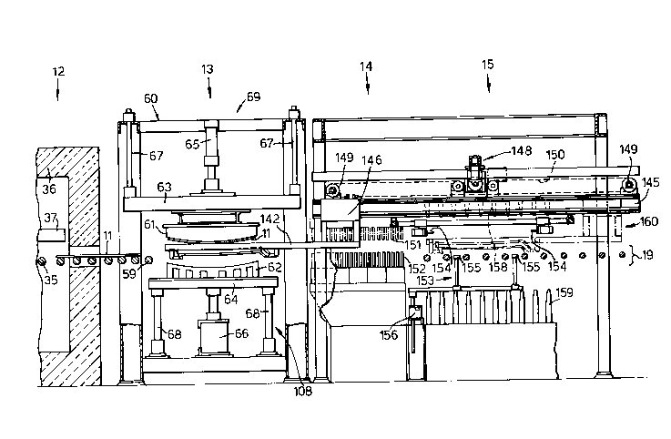
Figure 6 shows press bending station 13, quench station 14, and unloading station 15,
together with a fragment of furnace 12. The press 69 provided in press bending station 13
comprises a frame 60 with complementary upper and lower press members 61,62 mounted
for opposed reciprocating movement within it, such a press 69 being known in general terms
~ 2146936
- 19-
from a variety of documents including WO 93/14038 corresponding to US 5,279,635 the
disclosure of which is hereby incorporated herein by reference. Press members 61,62 are
mounted on upper and lower platens 63,64 which reciprocate in the vertical direction, guided
by guiding members 67,68. An elevator means 108 for the lower mould 62 is provided in the
form of ~ctllating cylinder 66; similarly, an actuating cylinder 65 is provided for upper mould
61. The press 69 is provided with third conveyor means in the form of rollers 59 to convey
the glass sheet 11 onto lower press rnember 62, but the majority of rollers 59 have been
omitted from the press station 13 for clarity. The operation of transferring sheet 11 onto
lower press member 62 is described below in conjunction with Figures 10, 11 and 12.
As mentioned earlier, it is desirable to provide the press 69 with wheels and a means
of centering and levelling so that it can be removed from the production line, the tooling
changed, and replaced and aligned with the line with minim~l delay. One such means 77 is
illustrated in Figures 7 to 9, and is known from EP 424,478 corresponding to US 4,872,898
the disclosure of which is hereby incorporated herein by reference. Figure 7 shows the lower
part of the press viewed from the side of the line, i.e. in the same direction as in Figure 6,
whereas Figures 8 and 9 show views taken along the longitudinal axis of the production line,
at right angles to the direction of Figures 6 and 7. The press frame 60 is provided with
grooved wheels 70 running on rails 71, enabling easy removal of the press. The working
height of the press is determined by ~himme~ pedestals 72, and the press is secured in its
working position by locking mech:~ni~m 73. The press is raised from its locked working
position to its unlocked transport position by reversible drive unit 74 operating rotary jacks
~ 2146936
75 via shafts 76 in a manner which will be explained in more detail with reference to Figures 8
and 9.
In Figure 8, the lower part of the press is shown in the raised position for transport in
or out of the production line. Wheels 70 are mounted on pivotable rocker arms 80.
Operating bar 81 bears upon rocker arms 80 via rollers 82, and as shown in Figure 8, the bar
has been driven downwards, causing wheels 70 to act as fulcrums and press frame 60 to be
raised. Operating bar 81 is actuated by rotary jacks 75, in turn actuated by drive unit 74 via
shafts 76, and upon actuation of the drive unit 74 in the appropriate sense, jacks 75 allow
operating bar 81 to rise to the position shown in Figure 9, thereby causing the press frame to
be lowered to its working height at which it rests upon pedestals 72. These have previously
been adjusted to the correct working height by addition or removal of shims.
The press shown in Figures 8 and 9 is designed to be moved out of its working
position in a right to left direction. When being moved back, a first approximate location is
provided by spring-loaded bumper 83 contacting stop plate 84. Bumper 83 may also contain
a proximity switch for control of the drive unit 74, thereby initi~ting lowering of the press.
As the press is lowered, accurate final location is provided by the locking mech~ni~m 73
which comprises a saddle 85 engaging a freely rotatable shaft 86. Saddle 85 defines a slot
which is shaped so that, if the press is slightly out of ~lignm~nt, lowering of the saddle 85
onto the shaft 86 urges the press into the correct position.
On entry into the press station, the heat-softened glass sheet (which may or may not
have been prelimin~rily bent as described above) is transferred from rollers onto the lower
mould. This is a critical point in the operation, because it is important both to locate the sheet
~~ 2 2146936
accurately upon the lower mould to achieve the correct shape during bending, and to avoid
the sheet being stationary upon the rollers for even the merest fraction of a second. The
localised len~ tult; changes caused by contact of a hot glass sheet with relatively cold
rollers are such that the merest pause will cause optical distortion in the glass, if not actual
marking of the surface. It is known to transfer the sheet to the mould by raising the mould
relative to the rollers, thereby lifting the sheet from the rollers. This operation has to be very
accurately timed in the sequence of bending operations to avoid introducing distortion.
Furthermore, the mould elevator means has to work against both the force of gravity and the
inertia of the relatively heavy lower mould and platen. During the development of the present
invention, it was found instead that lowering the rollers relative to the lower mould was
advantageous. This not only resulted in quicker transfer, but, since the rise of the lower
mould to press the sheet is then independent of transfer of the sheet it also resulted in
increased flexibility of operation. As a consequence, the timing of the rise of the lower mould
is less critical with this arrangement.
Figure 10 shows a plan view of the lower mould 62 together with an arrangement of
rollers 59 whlch may be used to transfer the sheet onto the mould. The principle of the
arrangement is that in the region of the mould, short rollers 170,171 are used to support the
heat-softened sheet, and these rollers do not pass over or under the mould so that they do not
impede its rise, but are engineered to terminate as close as possible to mould 62 to optimise
support for the sheet. This idea is known from WO 91/03432 corresponding to US
5,004,492 the disclosure of which is hereby incorporated herein by reference. Rollers 59
(which include short rollers 170,171) may be curved in conformity with mould 62, in which
-22- 21~6~36
case they comprise an inner flexible shaft 172 with an outer flexible sleeve 173 so that they
may rotate in a curved configuration. A full width roller 178 is also shown.
Rollers 59 may in general be driven by conventional sprocket and chain means,
arranged at the sides of the apparatus (i.e. the top and bottom of Figure 10), but these are not
shown in the drawing. However, those short rollers 171 which do not extend all the way to
the sides, which will be referred to as auxiliary rollers, require sepaLal~ drive means and
bearings. Auxiliary rollers 171 and truncated stub rollers 170 are rotatably supported on
bearings housed in brackets 174, as are shown in the lower half of Figure 10. It is to be
understood that the roller ends in(li~ate~ in the upper half of Figure 10 are similarly
supported, although the brackets have not been drawn in for these roller ends.
Auxiliary rollers 171 are driven from below via sprockets 175 which are preferably
centrally located on the roller. These sprockets may be driven by conventional engineering
means such as chains or further sprockets (not shown) powered by a driveshaft (not shown)
extending from one side of the appal~us under rollers 59. Auxiliary rollers 171 in fact
comprise two roller segments which are united, driven and also rotatably supported at a
convenient point such as the centreline of the apparatus. Support is by bearings within
pedestals 176.
Heat-softened glass sheets are conveyed onto mould 62 in the direction of arrow D by
rollers 59. Accurate location of the sheet on the rollers above mould 62 may be facilitated by
the use of conventional retractable end-stops 177. As described above, the sheet is removed
from rollers 59 as soon as it is in position above mould 62 by lowering rollers 59 and raising
-23- 21469 ~6
mould 62. At least the rollers within the c.r~u~ rence of mould 62 need to be lowered to
transfer the sheet; additional rollers may be lowered for engineering convenience.
As soon as the sheet is in position above the mould 62, rollers 59 are lowered by a
mechanism which is described below. If the timing of this operation is sufficiently accurate, it
is possible to dispense with the endstops 177 of Figure 10 altogether, as the sheet will lose
contact with rollers S9 and hence stop advancing just as it arrives in the correct position.
Sim-llt~neously with, or slightly later than, the lowering of the rollers, actuating cylinder 66
(Figure 6) is operated, causing lower platen 64 to rise together with lower mould 62, rollers
59, and their associated mech~ni~m
Figures 11 and 12 show a lowering means for lowering rollers 59 relative to lower
mould 62, mounted in press frame 60. Apart from the phanlo", outline of the upper part of
lower mould 62, the press members and their associated ~ct~l~ting cylinders, and guiding
members have all been omitted so as to reveal the roller-lowering means 107 better. Rollers
59 are mounted in a horizontal frame 100 which is itself supported by lower platen 64 so that
frame 100 and rollers 59 may reciprocate in the vertical direction with platen 64. Platen 64
therefore constitutes a common support for the rollers 59 and the lower mould 62. Frame
100 is mounted on a plurality of toothed racks 101, which are in engagement with pinions
102 mounted on axles 103 for rotational movement. The piston of a cylinder 104 is
connected to a crank 105, itself connected to other cranks 105 by connecting-rod 106. The
cranks 105 are fixedly mounted on pinion axles 103, so that generally horizontal movement of
the piston is converted to rotational movement of pinions 102, causing vertical movement of
racks lO1. In Figure 11 the rollers S9 are in the raised position, in which they are level with
~~ 24 al~6936
furnace conveyor rollers 35 (not shown in Figure 11), and slightly above the uppermost part
of lower mould 62 so as to receive a glass sheet 11 arriving from the furnace 12 and convey it
to a position directly above the lower mould, location of the sheet being assisted by
retractable stop members (not shown in Figures 11 and 12) if desired. An instant before the
sheet 11 is due to arrive in position directly above the lower mould 62, roller lowering
cylinder 104 and lower mould act~l~ting cylinder 66 (Figure 6) are operated so that the rollers
59 are lowered and lower mould 62 is raised, transferring the sheet 11 from the rollers 59 the
moment it has arrived in position.
Figure 12 shows the lowering means 107 of Figure 11 with the rollers 59 in the
lowered position. The position of lower mould 62 is in~iicated twice, once for reference in a
lower position corresponding to the position in which it is shown in Figure 11 (thereby
revealing the extent to which rollers 59 have been lowered), and again in a raised position
which it adopts after movement in the direction of arrow E. Rollers 59 would of course also
have been raised with mould 62.
The lowering means 107 may be supported on an independent frame member as an
altern~tive to the lower platen 64. When a means of preliminary shaping of the glass sheet is
employed, this may be similarly supported. It is desirable that a preliminary shaping means
extends to a point imme-1iately adjacent the lower mould, so that the shape of a pre-bent sheet
is m~int~ined by providing adequate support until the sheet is transferred onto the lower
mould. In this situation rollers 59 may comprise horizontal rollers 40 and inclined rollers 41
as shown in Figure 4. It is a matter of engineering convenience as to how many of the rollers
-25- 2l469~f~
59 which are outside the cir~ul-lrelence of the lower mould 62 are lowered together with the
rollers within the ci~culllre.ence of the lower mould in order to transfer the sheet.
Once located on the lower mould, the glass sheet is shaped by pressing it against the
upper mould whereby the sheet is shaped by pressing it between the comple---ell~y shaping
surfaces of the moulds. This may be achieved by raising the lower mould further, or by
lowering the upper mould, or by a combination of the two.
The upper mould (and consequently its shaping surface) is internally heated to reduce heat
loss from the glass sheet, and at least part of its shaping surface is provided with apel lul~s at
which the air pres~.lr~ may be reduced, i.e. it is a vacuum mould. Examples of intern~lly
heated vacuum upper moulds are shown in Figures 13 to 17.
Figures 13 and 14 show one possible design of vacuum upper mould 61a which is
heated by means of electrical resistance heating elements and is known from WO 93/14038
which corresponds to US 5,279,635. The mould 61a is of the solid and continuous type,
having a continuous (and full face) shaping surface 110 which is complementary to that of the
lower mould. Surface 110 is provided on a mould body 111 which is formed of any suitable
m~teri~l capable of with~t~ntling the elevated ~e-npel~lult;s to which it is subjected and may,
for example, advantageously be a refractory material such as a ceramic material. An
outwardly extending flange 112 integrally formed along, preferably, the entire peli,lle~l of
the mould body 111, cooperates with a plurality of L-shaped brackets 113 for mounting the
shaping element to a support plate 114 suitably attached to the upper platen 63 (Figure 6).
To provide a resilient non-abrasive surface for contact with the heat softened glass sheet and
to provide insulation, the shaping surface 110 is covered with one or two sheets 115 of
2146936
-26-
durable heat-resistant cloth, such as woven or knit fibreglass or the like. Each insulating cloth
sheet 115 is stretched tautly over the shaping surface 110 and held in place by suitable means.
A chamber 116 may be formed in the mould body 111, to serve as a manifold for a
positive or negative air pressure to assist in the shaping and handling of the glass sheets. To
that end, the shaping surface 110 is provided with a plurality of air passages 118 in
conllllunication with the chamber 116, and the mould body 111 is provided with a conduit
117 also in conmlunication with the chamber 116 and a vacuum pump or a source of air
under pressure. The air passages 118 may be, as shown, in the form of bores which may be
drilled, or a porous or less dense refractory m~te.ri~l, i.e. one containing small passages, can
be chosen for the mould body. Such a material would perrnit a flow of air through the
shaping surface without the need for the drilled passages. The bores or passages terminate at
a~lures in the shaping surface, which is thereby perforated, notwith~t~n(ling that it is a full
face shaping surface.
A negative air pressure, or vacuum, can thus be provided at the shaping surface of the
upper mould 61 to assist in retaining the sheet thereon, or conforming the sheet thereto. The
vacuum can then be utilized to support the sheet as the lower mould 62is lowered and a
shuttle carrier ring (Figure 19) is moved into position to transport the sheet out of the press
station. When the carrier ring is in position under the upper mould, the latter descends to a
position slightly above the ring. The air pressure at the apellules is suddenly increased to a
level above atmosphere pressure, so that the bent sheet is positively released from the upper
mould 61, and is placed accurately upon the carrier ring. This technique avoids the risk of
- 27 - 2~469~6
m~rking the sheet as a result of it falling a significant distance, and alleviates problems of
alteration of shape through inaccurate placement on the carrier ring.
The upper mould 61 is provided with a plurality of heating elements 119 extending
through it, which are of an electrical resistance type suitable to be employed in the refractory
mould body 111. The elements themselves are capable of reaching lelllpel~tulcs of the order
of 600C, producing ~Illpela~ules up to 400C at the shaping surface. Surprisingly, however,
it has been found that good optical quality and adequate tempering can be achieved with
shaping surface lempe~alult;s as low as 200C. The normal range of operating temperatures
used at the shaping surface is 200C -350C, a plefelled range is 220C -300C, and a
l~nlpel~lule of 250C is most preferred.
Elements 119 may be embedded in the mould body 111 by casting it with the elements
in place, or bores may be provided (e.g. by drilling) into which the elements are inserted. The
elements 119 are connected in conventional manner to a suitable control unit ~not shown) for
regulating the power. The elements may be connected for individual control, or grouped in
zones which are separately controlled. Thermocouples (not shown) are also provided within
the mould body 111 near the shaping surface 110 to provide lelll~lalule readings at
a~plopliate points to enable the lellll)elatures across the shaping surface to be controlled. A
further method of internally heating a vacuum mould is to pass hot air or gas through the
vacuum system (i.e. conduit 117, chamber 116, and passages 1 18), so that the hot air or gas
exits the apellures in the shaping surface, thereby heating it.
Figures 15 to 17 show an alternative upper mould 61b. Like upper mould 61a, this is
also a heated vacuum mould, but the heating is achieved in a novel fashion, by passage of a
~ 2146g36
- 28 -
hot fluid through channels in the mould. The mould is cast from an aluminium alloy durable
to high temperatures and includes bores which traverse the shorter dimension of the mould
when seen in plan. The bores are connected to tubes 120, which may be of steel, or
alternatively the tubes 120 pass right through the mould, being cast into the mould. On one
side of the mould the tubes 120 are connected to an inlet manifold 121, and on the other side
they are connected to an outlet manifold 122, and a hot fluid is circulated through the mould
via the manifolds and tubes. Suitable fluids are mineral oils or synthetic oils which are of low
volatility at 300 C and have a specific heat capacity of 1.5 to 2.5 KT/kg. Using such oils at
300C, le",l)el~tures of 200 C to 250 C can be achieved at the shaping surface 110 with
tubes 120 betwciell 8 and 10 mm in intern~ ler and a fluid velocity of about 1
dm3/second. Alternatively, hot air or gas may be passed through the conduits. The shaping
surface lt;lll~X~ Ult; may be controlled by controlling either the ~elllpelature or the rate of
flow of the fluid.
As with upper mould 61a, mould 61b may be provided with an internal chamber
connected to a source of negative or positive pressure, and in communication with apel lules
in the shaping surface. In fact the particular mould shown in Figures 15-17 is provided with
three chambers comprising a central chamber and two end chambers arranged along the
length of the mould. The central chamber is connected to vacuumlair conduit 123, and
likewise the end chambers are connected to vacuumlair conduit 124. This multiple chamber
arrangement makes it possible for example to provide differing degrees of suction in the end
regions of the shaping surface compared with in the middle, which is advantageous for certain
-29- 21469~6
shapes. The arrangement is not limited to mould type 61b, but may also be provided in type
61a.
The important differences between the two types of upper mould are the means of
heating and the m~teri~l~ used. Each type of material has advantages for dirrelellt situations.
Refractory mould 61a is more durable and the mould material does not in practice pose any
constraints on operating ~l~pe~lule. However, the alunli-liu--- alloy of mould 61b has a
thermal expansion such that it expands about the same amount, when heated from ambient to
its working temperature of 200 C -250C, as a glass sheet expands when heated from
ambient to its bending temperature of around 600 C. This means that the mould can be
m~chinçd according to the shape of the bent sheet required at ambient lt;nl?el~tul~;, without
any compensation for thermal expansion. Because the material is m~chin~ble, changes to the
mould may be made which call for removal of material, whereas a new refractory mould
woùld normally have to be cast, unless a modern m~hin~ble ceramic had been used. While it
is p,~re,led that the ceramic mould is electrically heated, and the alull~niu--- alloy mould is
fluid-heated, it is of course possible to engineer dirrelel~- combinations of mollld m~teri~l~ and
heating techniques.
Figure 18 shows the lower mould 62 which is of female or concave form, and
comprises a shaping surface in the form of a continuous shaping rim 130 complen~ell~y in
outline and elevation to the periphery of the full face shaping surface 110 of the upper mould
61. The end walls of the mould are provided with vertically extending slots 131 to
accommodate the supports and driveshafts for the rollers 59 (not shown on Figure 18) if the
lower mould 62 is raised relative to the rollers as described above. Alternatively, lower
~30- 2146~6
mould 62 can take the form of a shaping rail supported on upright rods, between which the
roller supports and drives can be accommodated.
Having thus been bent, and placed upon the carrier ring of a shuttle means, the glass
sheet 11 is transported by the shuttle means into the quench station 14 (Figures 1,6), where it
is tempered, and finally into unloading station 15. In addition to the press bending station 13
described earlier, Figure 6 shows the quench and unloading stations 14,15, and the shuttle
means 160, while Figure 19 shows details of part of the shuttle means.
Referring to Figure 19, the shuttle means comprises a carrier ring 140 which conforms
in outline and elevation to the periphery of the bent glass sheet. Ring 140 is supported within
a frame 141 which is itself supported on two cantilevered support arms 142 by means of
locating pins 143 and V-shaped rests 144. Support arms 142 depend from shuttle glide rails
145 (Figure 6) by means of glide plates 146, which are connected to the shuttle drive system
via connectors 147. The drive system (Figure 6) comprises drive unit 148, idler pulleys l 49
and chain 150 (shown as a dashed line), which together enable the glide plates 146 and
~tt~hed structure to travel back and forth along the glide rails 145.
Still referring to Figure 6, quench station 14 comprises opposed upper and lower
blastheads 151,152 disposed and operable to direct opposing streams of a cooling fluid such
as air towards and against the opposite surfaces of the bent glass sheèt 11 in known fashion.
When the bent glass sheet enters the que-nch station, it is still sufficiently hot to undergo
s~ti~factory lem~eling due to the effect of the heated tooling, yet it has not lost the shape
accurately imparted to it in the press station 13 because it is supported by the carrier ring.
During tempering, the drive unit 148 causes the carrier ring to reciprocate rapidly over a short
~~ 31 21~16936
~list~n~e, thereby causing an oscillating movement of the sheet in the quench, as is usually
practised in the tempering art.
Having been tempered, the sheet 11 is transferred to the unloading station 15, which is
known from WO 90/11973 corresponding to US 4,883,526 (the disclosure of which is hereby
incorporated herein by reference). The unloading app~tus comprises sheet lift meçh~ni~m
153 and a support mechanism comprising retractable pins 154. Sheet-engaging cross-
members 155 of the lift 153 are propelled upwards by drive unit 156 so as to lift sheet 11
from carrier ring 140 up to slightly above the level of pins 154. Pins 154 are extended into
the region below the lower surface of sheet 11 so as to support it when cross-,--el-,bers 155
descend. The shuttle carrier ring can then be removed from unloading station 15, and return
to the press station 13 for the next sheet. In the m~ntimç, cross-members 155 rise again to
collect the sheet from support pins 154 and lower it onto the take-off conveyor 157. During
the unloading procedure, the sheet may be further cooled by air from opposed bl~th~ds
158,159, so that on leaving the bending and tempering apparatus it is cool enough for
subsequent operations.