Language selection

Search

Patent 2147296 Summary

Third-party information liability

Some of the information on this Web page has been provided by external sources. The Government of Canada is not responsible for the accuracy, reliability or currency of the information supplied by external sources. Users wishing to rely upon this information should consult directly with the source of the information. Content provided by external sources is not subject to official languages, privacy and accessibility requirements.

Claims and Abstract availability

Any discrepancies in the text and image of the Claims and Abstract are due to differing posting times. Text of the Claims and Abstract are posted:

  • At the time the application is open to public inspection;
  • At the time of issue of the patent (grant).
(12) Patent Application: (11) CA 2147296
(54) English Title: METHOD OF REDUCING ROCK DAMAGE TO A TRAILER HAVING FENDERS
(54) French Title: METHODE PERMETTANT DE REDUIRE LES DOMMAGES CAUSES PAR LES CAILLOUX SUR UNE REMORQUE EQUIPEE D'AILES
Status: Deemed Abandoned and Beyond the Period of Reinstatement - Pending Response to Notice of Disregarded Communication
Bibliographic Data
(51) International Patent Classification (IPC):
  • B60R 19/54 (2006.01)
  • B62D 25/16 (2006.01)
  • B62D 35/00 (2006.01)
(72) Inventors :
  • DIXON, JOSEPH STEPHEN (Canada)
(73) Owners :
  • JOSEPH STEPHEN DIXON
(71) Applicants :
(74) Agent:
(74) Associate agent:
(45) Issued:
(22) Filed Date: 1995-04-19
(41) Open to Public Inspection: 1995-10-21
Availability of licence: N/A
Dedicated to the Public: N/A
(25) Language of filing: English

Patent Cooperation Treaty (PCT): No

(30) Application Priority Data:
Application No. Country/Territory Date
08/230,559 (United States of America) 1994-04-20

Abstracts

English Abstract


A method of reducing rock damage to a trailer
having fenders is described. The method involves a
single step of securing deflector shields to opposed
sides of a trailer. Each deflector shield is angled
outwardly and rearwardly from one of the opposed sides of
the trailer to a peripheral edge of a fender. Each
deflector shield extends to a height substantially equal
to a top of the fender.


Claims

Note: Claims are shown in the official language in which they were submitted.

THE EMBODIMENTS OF THE INVENTION IN WHICH AN EXCLUSIVE
PROPERTY ARE CLAIMED AS FOLLOWS:
1. A method of reducing rock damage to a trailer
having fenders, comprising the step of:
securing deflector shields to opposed sides of
a trailer, each deflector shield angled outwardly and
rearwardly from one of the opposed sides of the trailer
to a peripheral edge of a fender, each deflector shield
being of a height at least as high as a top of the
fender.
2. An improvement in a trailer having fenders,
comprising:
deflector shields secured to opposed sides of
the trailer, each deflector shield being angled outwardly
and rearwardly from one of the opposed sides of the
trailer to a peripheral edge of a fender, each deflector
shield being of a height at least as high as a top of the
fender.

Description

Note: Descriptions are shown in the official language in which they were submitted.


- 21~729~
Title: A ~BTHOD OF RBDUCING ROC~ DAMAGB
TO A TR~ILBR HAVING FENDBR8
~C~GROUND OF THB INVBNTION
A number of trailer styles have fenders. These
fenders presently sustain damage from stones and other
road debris thrown up by the wheels of the tow vehicle.
A portion of the stones and road debris deflect off the
fenders and also cause damage to the sides of the
trailer.
A need exists for a device that will protect
the sides of trailers having fenders from damage
inflicted by stones thrown up from the road bed. The
present invention has as its object a method of reducing
rock damage to a trailer having fenders.
The invention in its general form will first be
described, and then its implementation in terms of
specific embodiments will be detailed with reference to
the drawings following hereafter. These embodiments are
intended to demonstrate the principle of the invention,
and the manner of its implementation. The invention in
its broadest and more specific forms will then be further
described, and defined, in each of the individual claims
which conclude this Specification.
8UMNARY OF T~E INVBNTION
According to one aspect of the present

2147295
_ 2
invention there is provided a method of reducing rock
damage to a trailer having fenders, comprising the step
of securing deflector shields to opposed sides of the
trailer forward of each fender. Each deflector shield is
angled outwardly and rearwardly from one of the opposed
sides of the trailer to a peripheral edge of a fender.
Each deflector shield is of a height at least as high as
a top of the fender.
With the method, as described above, the
deflector shield deflects stones and road debris that
would otherwise cause damage to the fenders and sides of
the trailer. The method also has a number of secondary
benefits. A more dynamic air flow is created in the area
of the fenders that contributes to trailer stability and
improves fuel economy. When driving in wet conditions,
the deflector shield deflects the spray of slush and
water away from the sides of the trailer.
According to another aspect of the present
invention there is provided an improvement in a trailer
having fenders which is comprised of deflector shields
secured to opposed sides of the trailer forward of each
finder. Each deflector shield is angled outwardly and
rearwardly from one of the opposed sides of the trailer
to a peripheral edge of a fender. Each deflector shield
is of a height at least as high as a top of the fender.
The foregoing summarizes the principal features

21~296
~_ 3
of the invention and some of its optional aspects. The
invention may be further understood by the description of
the preferred embodiments, in conjunction with the
drawings, which now follow.
BRIEF n~CPTPTION OF THF DRAWING8
These and other features of the invention will
become more apparent from the following description in
which reference is made to the appended drawings,
wherein:
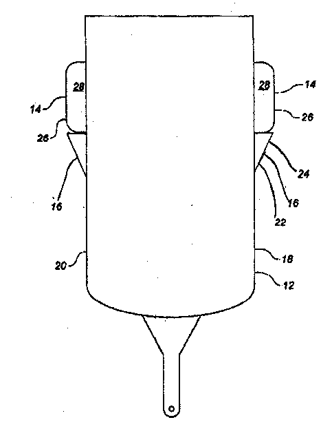
Figure 1 is a top plan view of a trailer which
has been modified in accordance with the teachings of the
present method;
Figure 2 is a perspective view of one variant
of the deflector of the invention positioned on the side
of the trailer, with the fender omitted for clarity.
Figure 3 is a perspective view of another
variant of the deflector of the invention, positioned on
the side of the trailer with the fender omitted for
clarity.
D~TAILED DE8CRIPTION OF THE rK~R~D ~MBODINBNT
The preferred method of reducing rock damage to
a trailer having fenders will now be described with
reference to Figure 1.
Referring to Figure 1, there is illustrated a

21~729B
trailer 12 having fenders 14. The method involves a
single step of securing deflector shields 16 to opposed
sides 18 and 20 of trailer 12. Each deflector shield 16
has a first front end 22 and a second trailing end 24.
First end 22 of each deflector shield 16 is secured to
opposed sides 18 and 20 of trailer 12. Each deflector
shield 16 is angled outwardly and rearwardly from opposed
sides 18 and 20 of trailer 12 to a peripheral edge 26 of
one of fenders 14. Each deflector shield 16 extends to
a height substantially equal to a top 28 of one of
fenders 14. Deflector shields 16 serve to deflect stones
and road debris away from fenders 14 and sides 18 and 20
of trailer 12.
Referring to Figure 2, a first variant of the
deflecto-guard deflector shield 16 is shown in
perspective view positioned against the side 18 of a
trailer, forward of the fender which, for clarity, is
omitted from this view. In this variant the deflecting
surface 16a is supported by a sheet metal flange 36
attached between the trailer side 18 and to the trailing
end 24 and top edge 25 of the deflector surface 16a.
This flange 36 may be curved to extend over the top of
the deflector 16 to enclose the top of the deflecto-
guard; or it may contain an opening 38 to allow air to
pass therethrough. If a bottom (not shown) is provided
to the deflector 16, the opening 38 may serve to provide

2l4~296
access to the interior for storage. The front end 22 of
the deflecting surface 22 may be mounted directly to the
side of trailer 18.
The guard 16 and flange 36 may be made of sheet
material of, but not limited to, aluminum. Such sheet
material may be of steel, fibreglass or plastic,
whichever would be most suitable to meet conditions.
Referring to Figure 3, another variant
preferably made of aluminum is shown. In this variant
the front end 22 of the deflector surface 16a is again
fixed to the side of the trailer 18. A single, central
stiffening flange 30 extends outwardly from the trailer
side 18 as a support brace to hold deflector-guard to the
trailer side 18. Inwardly bent safety flanges 24a and
25a along the rear 24 and top edges 25 reduce the dangers
of exposed sharp edges.
It will be apparent to one skilled in the art
that modifications may be made to the embodiment
illustrated in the Figures without departing from the
spirit and scope of the invention s hereinafter defined
in the claims. In particular, it will be apparent that
although deflector shields 16 should extend at least as
high as top 28 of fenders 14, it can be extended higher
without adversely affecting the function of deflector
shields 16.

6 21~7296
CONCLU~ION
The foregoing has constituted a description of
specific embodiments showing how the invention may be
applied and put into use. These embodiments are only
S exemplary. The invention in its broadest, and more
specific aspects, is further described and defined in the
claims which now follow.
These claims, and the language used therein,
are to be understood in terms of the variants of the
invention which have been described. They are not to be
restricted to such variants, but are to be read as
covering the full scope of the invention as is implicit
within the invention and the disclosure that has been
provided herein.

Representative Drawing
A single figure which represents the drawing illustrating the invention.
Administrative Status

2024-08-01:As part of the Next Generation Patents (NGP) transition, the Canadian Patents Database (CPD) now contains a more detailed Event History, which replicates the Event Log of our new back-office solution.

Please note that "Inactive:" events refers to events no longer in use in our new back-office solution.

For a clearer understanding of the status of the application/patent presented on this page, the site Disclaimer , as well as the definitions for Patent , Event History , Maintenance Fee  and Payment History  should be consulted.

Event History

Description Date
Inactive: IPC from MCD 2006-03-11
Application Not Reinstated by Deadline 2003-04-22
Time Limit for Reversal Expired 2003-04-22
Inactive: Status info is complete as of Log entry date 2002-06-05
Deemed Abandoned - Failure to Respond to Maintenance Fee Notice 2002-04-19
Inactive: Abandon-RFE+Late fee unpaid-Correspondence sent 2002-04-19
Letter Sent 1999-04-28
Reinstatement Requirements Deemed Compliant for All Abandonment Reasons 1999-04-15
Deemed Abandoned - Failure to Respond to Maintenance Fee Notice 1998-04-20
Deemed Abandoned - Failure to Respond to Maintenance Fee Notice 1997-04-21
Inactive: Adhoc Request Documented 1997-04-21
Application Published (Open to Public Inspection) 1995-10-21

Abandonment History

Abandonment Date Reason Reinstatement Date
2002-04-19
1998-04-20
1997-04-21

Maintenance Fee

The last payment was received on 2001-03-20

Note : If the full payment has not been received on or before the date indicated, a further fee may be required which may be one of the following

  • the reinstatement fee;
  • the late payment fee; or
  • additional fee to reverse deemed expiry.

Patent fees are adjusted on the 1st of January every year. The amounts above are the current amounts if received by December 31 of the current year.
Please refer to the CIPO Patent Fees web page to see all current fee amounts.

Fee History

Fee Type Anniversary Year Due Date Paid Date
Reinstatement 1999-04-15
MF (application, 4th anniv.) - small 04 1999-04-19 1999-04-15
MF (application, 3rd anniv.) - small 03 1998-04-20 1999-04-15
MF (application, 5th anniv.) - small 05 2000-04-19 2000-04-12
MF (application, 6th anniv.) - small 06 2001-04-19 2001-03-20
Owners on Record

Note: Records showing the ownership history in alphabetical order.

Current Owners on Record
JOSEPH STEPHEN DIXON
Past Owners on Record
None
Past Owners that do not appear in the "Owners on Record" listing will appear in other documentation within the application.
Documents

To view selected files, please enter reCAPTCHA code :


To view images, click a link in the Document Description column (Temporarily unavailable). To download the documents, select one or more checkboxes in the first column and then click the "Download Selected in PDF format (Zip Archive)" or the "Download Selected as Single PDF" button.

List of published and non-published patent-specific documents on the CPD .

If you have any difficulty accessing content, you can call the Client Service Centre at 1-866-997-1936 or send them an e-mail at CIPO Client Service Centre.

({010=All Documents, 020=As Filed, 030=As Open to Public Inspection, 040=At Issuance, 050=Examination, 060=Incoming Correspondence, 070=Miscellaneous, 080=Outgoing Correspondence, 090=Payment})


Document
Description 
Date
(yyyy-mm-dd) 
Number of pages   Size of Image (KB) 
Representative drawing 1998-05-14 1 7
Abstract 1995-10-20 1 12
Description 1995-10-20 6 181
Claims 1995-10-20 1 22
Drawings 1995-10-20 2 27
Courtesy - Abandonment Letter (Maintenance Fee) 1998-05-18 1 186
Notice of Reinstatement 1999-04-27 1 172
Reminder - Request for Examination 2001-12-19 1 117
Courtesy - Abandonment Letter (Maintenance Fee) 2002-05-20 1 183
Courtesy - Abandonment Letter (Request for Examination) 2002-06-02 1 173
Fees 2000-04-11 1 33
Fees 2001-03-19 1 33
Fees 1999-04-14 1 41
Fees 1997-04-15 1 38