Note: Descriptions are shown in the official language in which they were submitted.
2147697
20025.0005
VERSATILE AND USER FRIENDLY ~lN~ DISPLAY SYSTEM
The present invention relates generally to panel display
structures for trade show exhibition booths and the like.
Various types of display systems have been provided wherein
the display pan-els- are supported by various kinds o-f pins-,
connectors, and hinges. See, for example, U.S. patents
2,406,729, 3,889,736, 3,913,656, 4,134,439, 4,263,761, 4,375,829,
4,448,003, 4,491,166, 4,619,304, 4,823,858, 4,865,111, 4,891,922,
4,924,931, 4,958,671, 4,979,554, and 4,986,038.
A display system may typically comprise a plurality of
rectangular panel frames hinged together so that they may be
folded along vertical axes for storage and transport. Typical
metallic hinges placed on the frames would undesirably be
conspicuous and not provide a seamless effect. If the unit is
forced in the wrong direction, such a metallic hinge may be
susceptibIe to becoming bent.
U.S. patent 4,823,858 to Perutz discloses a hinged display
system wherein each hinge permits 360 degrees relative rotational
movement between adj~ent p~n~l~ Ea~ ~ing~ compri~s f-i-rst an~-
second hinge segments secured to adjacent first and second
display panels. Each hinge segment includes upper, middle, and
lower portions that are arranged in vertically spaced relation.
The hinge segments are interconnected by a pair of link pieces.
One link piece is pivotally connected to the upper and middle
portions of the segments and the second link piece is pivotally
connected to the middle and lower portions of the segments. When
one segment pivots 180 degrees relative to the other segment, one
pivot axis is utilized, and, when the one segment pivots through
a second arc of 180 degrees, a second pivot axis is utilized.
When the adjacent panels are disposed in a substantially coplanar
2147697
- 2 - 20025.0005
relation, the hinges are said to be substantially concealed.
Such a structure is expensive to manufacture.
U.S. patent 4,619,304 to Smith discloses a hinged structure
wherein supports are hinged together. The hinge comprises two
members each made of a resiliently flexible strip material such
as a spring stainless steel. Each member is S-shaped and passes
partially around each support, and the two members together form
a letter X or figure 8 configuration. The members are fastened
alongside each support so that the members are tensioned round
the supports.
A display system may, for example, comprise two or more sets
of hinged panels and a set of header panels disposed at the top
of the structure. Header panels may be positioned between a pair
of hinged panels as an accent stripe, as seen in U.S. patent
4,865,111 to Perutz. It is considered desirable to have the
versatility to interchange the header panels with the sets of
hinged panels so that they serve optionally as a header or an
accent stripe or are disposed at the bottom of the structure.
Each of the elongate segments of a frame is typically a
single piece which comprises a central portion and a pair of
flange portions at each edge extending inwardly from an outer
surface over the segment length, a panel being insertable between
the central portion and each of the flange portions. Such a
construction requires removal of an elongate segment for
insertion or removal of a panel. A segment is typically
removably attached by means of spring-loaded bullets in holes,
requiring the use of one's finger to apply enough force against
the bullets to disconnect the segment. It is difficult to insert
a finger to push on the bullet and therefore difficult to remove
the segment.
2147697
- 3 - 20025.0005
It is accordingly an object of the present invention to
provide a lightweight portable display system which is cost
effective for the end user.
It is another object of the present invention to provide
such a display system which is versatile, i.e., it may be
converted and used optionally as three separate systems, wherein
the header frames may be provided at the top as a header, at the
middle as an accent stripe, or at the bottom.
It is a further object of the present invention to provide
such a display system wherein the hinges are not subject to
breakage and allow relative rotation throughout substantially 360
degrees and are inconspicuous so as to effect a seamless
appearance.
It is yet another object of the present invention to provide
such a display system wherein the hinges may be installed
inexpensively, yet are rugged and reliable.
It is another object of the present invention to provide
such a display system which allows the panels to be easily and
quickly replaced.
In accordance with the present invention, first and second
sets of panel frames and a plurality of header frames are
interchangeably connectable so that the header frames are
optionally above, between, or below the first and second sets of
panel frames.
Also in accordance with the present invention, a hinge for a
pair of panel frames comprises at least two straps composed of a
flexible material. One of the straps is attached to the front
edge of one frame segment and the rear edge of the other frame
segment, and the other strap is attached to the rear edge of the
one frame segment and the front edge of the other frame segment
so that the attachment of the straps to the front edges defines a
- 2147697
- 4 - 20025.0005
hinge axis about which the frames are rotatable through a first
arc, and the attachment of the straps to the rear edges defines a
hinge axis about which the frames are rotatable through a second
arc. Cut-outs are provided in the segments, and a complementary
insert effects pinching of the respective strap end portion
within each cut-out between the respective segment and the
insert, which may then be tightly connected for securely
attaching the strap.
Further in accordance with the present invention, at least
one of the frame segments in fonmed as two parts wherein a first
elongate member serves as a tie bar between a pair of segments
and is adapted to provide an opening for insertion of a panel,
and a second elongate member is removably attachable to the first
elongate member and closes the opening to prevent insertion and
removal of panels.
The above and other objects, features, and advantages of the
present invention will be apparent in the following detailed
description of a preferred embodiment thereof when taken in
conjunction with the accompanying drawings wherein the same
reference numerals denote the same or similar parts throughout
the several views.
BRIEF DESCRIPTION OF THE DRAWINGS
Fig. 1 is a perspective view of a panel display system,
shown set up for viewing, which embodies the present invention.
Fig. 2 is a view similar to that of Fig. 1 showing the
panels partially folded up.
Fig. 3 is a partially exploded view of one of the panel
frames of the display system.
Fig. 4 is a partially exploded view of one of the header
frames of the display system.
21~7697
- 5 - 20025.0005
Fig. 5 is a partial perspective view showing the sets of
panel frames of the display system folded up.
Fig. 6 is a perspective view showing a set of panel frames
of the display system folded up and illustrating removal of a cap
member so that a panel may be inserted.
Fig. 7 is a view similar to that of Fig. 6 showing the panel
frames with a panel being inserted therein.
Fig. 8 is an exploded view of half of a hinge for a pair of
the panel frames illustrating attachment of a strap.
Fig. 9 is a partial side view of the hinge half, when the
frames are in a folded condition, with the strap attached.
Fig. 10 is a horizontal sectional view thereof with the
frames in a folded condition.
Fig. 11 is a view similar to that of Fig. 10 with the frames
in an unfolded condition.
Fig. 12 is a view similar to that of Fig. 1 showing the
header frames between the two sets of panel frames.
Fig. 13 is a view similar to that of Fig. 1 showing the
header frames below the two sets of panel frames.
Fig. 14 is a sectional view, taken along lines 14-14 of
Fig. 3, of the lower frame segment of the frame of Fig. 3.
Fig. 15 is a section view, taken along lines 15-15 of
Fig. 3, of the upper frame segment of the frame of Fig. 3 with
the segment shown in an exploded view.
Fig. 16 is a view similar to that of Fig. 9 showing both
halves of the hinge and with the frames in a folded condition.
Fig. 17 is a partial front view of the hinge and respective
frames in an unfolded condition and the panels inserted.
21~7697
- 6 - 20025.0005
DETAILED DESCRIPTION OF THE PREFERRED EMBODIMENT
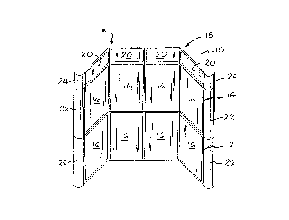
Referring to Fig. 1, there is shown generally at 10 a panel
display system set up for display at a trade show or the like.
The display system 10 comprises a first or lower set 12 of four
panels 16 hingedly connected together for ease of set-up, take-
down, and transport. The system 10 also comprises a second or
upper set 14 of four panels 16 similarly hinged together. The
system 10 further comprises two pairs 18 of header panels 20 each
pair hingedly connected together as hereinafter described
relative to panels 16.
The sets of panels 16 and the pairs of header panels 20 are
foldable, as illustrated in Fig. 2, into a face-to-face and back-
to-back relation for transport and storage, the sets 12 and 14 of
panels being shown folded in Fig. 5. The folded sets 12 and 14
of panels may be packed by laying one on top of the other in a
shipping container. Dividing the header panels 20 into two pairs
allows efficient use of the shipping container space in that the
folded pairs of header panels 20 may be laid side-by-side on top
of the sets 12 and 14 of panels. In order to achieve such
efficient packing, the header panels 20 desirably have less than
half the height of the panels 16. For example, each header panel
20 may perhaps have a width of about 40 inches and a height of
about 12 inches, while each panel 16 may have the same width and
a height of perhaps about 28 inches.
The sides of the display system 10 may be provided with trim
assemblies such as curved panels 22 and 24 connected to edges of
the outer ones of the panels 16 and 20 respectively. Since these
trim assemblies, which are not shown in Fig. 2, do not form any
part of the present invention, they are not described further
herein.
~ . ~
2I4 7697
-
- 7 - 20025.0005
As seen in Fig. 7, the panels 16, which are generally
inflexible and typically rectangular and composed, for example,
of a thin light weight material weighing perhaps about 1 pound
and having a thickness of perhaps about 3/16 inch, are held along
their edges by rectangular (or otherwise complementary in shape)
frames 26 which are composed of extruded segments of lightweight
material, such as all~m;nl]ml which are suitably joined together,
as described hereinafter, to form a strong rigid frame having
miter joints, i.e., the ends of the segments are chamfered at an
angle of 45 degrees, as illustrated at 27 in Fig. 3, to mate with
similarly chamfered ends of other segments.
One of the frames 26 is shown in Fig. 3. Frame 26 includes
upper and lower elongate segments 28 and 30 respectively joined
to longer elongate side segments 32 and 34. Conventionally,
frame segments have been joined by a swaged or crimped joint that
cannot be disssembled. In accordance with the present invention,
the frame segments are joined by L-shaped key members 50 so as to
allow relatively easy field repair and the adding or subtracting
of additional frames. The segments and key members may be
extruded all~m;nl]m or composed of other suitable material. Each
key member 50 has two legs 52 oriented at a right angle to each
other.
A sectional view of lower segment 30 is shown in Fig. 14,
the sectional views of segments 32 and 34 being the same except
that if one of the segments 32 and 34 is hingedly connected to a
segment of an adjoining frame, it will be modified as discussed
hereinafter. However, if desired, one or more of these segments
may be similar to upper segment 28, which will be described
hereinafter. Referring to Fig. 14, segment 30 has an outer
surface 36 defined by a generally planar portion 38. Extending
inwardly from portion 38 is a generally rectangular central
2I4 7697
- 8 - 20025.0005
portion 40 and a pair of flange portions 42, the flanges 42
extending from the elongate edges respectively of portion 38 and
being generally parallel to sides of the central portion 40
whereby the edges of panels 16 are held within the spaces or
grooves, illustrated at 44, between the flange portions 42
respectively and the respective sides of the central portion 40
over the entire perimeter of the frame 26. The segment 30 is
formed to have an elongate generally rectangular channel 46
extending from end to end through the length of the central
portion 40. The channel 46 is formed to be narrowed adjacent
portion 38 over the length of segment 30 to define a pair of
shoulders 48. The legs 52 of a key mem.ber 50 are received within
the channels 46 respectively of a pair of frame segments to be
joined. The legs 52 are sized to fit snugly within the
respective channels 46 and abutting the shoulders 48. A leg 52
is secured to the respective segment by a suitable flat head
screw, illustrated at 54, which is received in an aperture,
illustrated at 56, in segment portion 38 and is threadedly
received in a threaded aperture, illustrated at 58, in the leg
52. Apertures 56 are countersunk for receiving the screw heads.
While representative screws and the like are shown in the
drawings, it should be understood that all such screws and the
like may not be shown but may be ascertained from the description
and the drawings, utilizing principles commo~ly known to those or
ordinary skill in the art to which this invention pertains.
Referring to Fig. 4, a frame for a header 20 is shown
generally at 60. The header frame 60 is constructed of
relatively long upper and lower frame segments 62 and 64
respectively, relatively short side segments 66 and 68, and key
members 70 which may be similar to frame segments 28, 30, 32, and
34 respectively and key mem.bers 50. The key members 70 may be
21~76g7
- 9 - 20025.0005
similarly attached to the segments by screws 72, which may be
similar to screws 54, received in countersunk apertures,
illustrated at 74, in the respective segments and threadedly
received in threaded apertures, illustrated at 76, in the key
members 70. Unless otherwise specified herein, header frames 60
may be similar to, but smaller in size than, frames 26.
Descriptions hereinafter with respect to panel frames 26 are
therefore also applicable to header frames 60, which contain
header panels 20.
Referring to Fig. 5, hinges are shown generally at 80
connecting the middle two of the four panel frames 26 of each of
the lower and upper sets 12 and 14 respectively. There may be
perhaps 4 to 8 hinges 80 spaced along the length of the
respective segments for hingedly connecting a pair of frames.
The first and second frames and the third and fourth frames for
each set are similarly connected by hinges 80 on the left side as
seen in Fig. 5, and these hinges are therefore not shown. The
hinged connections of the frames allow them to be folded so as to
overlie each other compactly in face-to-face and back-to-back
relation as shown in Fig. 5 for storage and transport.
In order that the lower and upper panel sets 12 and 14
respectively may be easily connected interchangeably with each
other and with the headers 20, in accordance with the present
invention, each end portion of each of the upper and lower
segments 28 and 30 respectively of both the lower and upper sets
12 and 14 respectively of frames as well as each end portion of
each of the upper and lower segments 62 and 64 respectively of
header frames 60 is provided with a threaded aperture 82 and an
unthreaded aperture 84. Each of the apertures 82 and 84 extends
entirely through the respective segment including portion 38 and
central portion 40. Threaded apertures 82 are positioned on
21~7~97
- 10 - 20025.0005
lower segments to be in alignment with unthreaded apertures 84 on
upper segments to which a panel frame is to be joinable and are
positioned on upper segments to be in alignment with unthreaded
apertures 84 on lower segments to which a panel frame is to be
joinable. Pins 86 have threaded end portions 88 (Fig. 6) which
are threadedly received in the threaded apertures 82 and shank
end portions 90 which extend outwardly from the outer surfaces 36
of the respective segments. The shank portions 90 are snugly
received in the correspondingly aligned unthreaded apertures 84
in an upper or lower segment of a frame to which a frame
containing the pins 86 is to be mounted. Thus, as shown in Fig.
6, the threaded apertures 82 in each end portion of the upper
segments of both panel frames and header frames are located
outwardly of the unthreaded apertures 84, and the threaded
apertures 82 in each end portion of the lower segments of both
panel frames and header frames are located inwardly of the
unthreaded apertures 84 so as to be in alignment with
corresponding unthreaded apertures 84 in upper segments of both
panel frames and header frames. To mount any combination of
panel and header frames together, the shanks 90 of the pins 86
threadedly secured to a segment of one frame are received in
corresponding aligned unthreaded apertures 84 of the
corresponding segment of the other frame, and the shanks 90 of
the pins 86 threadedly secured to the corresponding segment of
the other frame are received in the corresponding aligned
unthreaded apertures 84 of the one frame. This allows a display
to be easily set up with the headers 20 interchangeably at the
top, as shown in Figs. 1 and 2, or between the lower and upper
sets 12 and 14 respectively of panels, as shown in Fig. 12, to be
an accent stripe, or at the bottom, as shown in Fig. 13. Fig. 13
also shows panel set 12 interchangeably positioned above panel
2147697
- 11 - 20025.0005
set 14. If desired, the panel assembly 10 may be divided into
two table-top displays.
As seen in Fig. 5, the sets 12 and 14 of panels are
preferably stacked with the hinged sides matching, the pins 86
sticking up from the lower set and sticking down from the upper
set.
As seen in Fig. 14, an edge of a panel 16 is held between a
flange portion 42 and the central portion 40 of a segment. Such
a construction has conventionally required a segment to be
detached from the frame for insertion and removal of a panel, but
it is considered difficult to insert a finger into a hole to push
on a spring-loaded bullet to remove a segment. Referring to
Figs. 6 and 15, in order to more easily insert or remove a panel,
in accordance with the present invention, the upper segment 28 or
other suitable segment comprises two elongate pieces. One piece
92, which may be called the tie bar, is generally rectangular in
cross section and contains a central portion 40 including channel
46 and shoulders 48. The outer longitl]~; n~l edges of the tie bar
92 have notches 94, i.e., right-angled longitl]~;n~l cut-outs.
The tie bar 92 is suitably connected to side segments 32 and
34 such as by screws 96 (illustrated in Fig. 3) which are
received in apertures, illustrated at 98, in the inner portion of
the tie bar 92 and threadedly received in threaded apertures 100
in the respective key members 50 so that the tie bar may be left
permanently connected.
The second piece 102 of the upper segment 28, which may be
called a top cap, contains a planar portion 38 including outer
surface 36 and flange portions 42. A pair of longitl]~; n~l ridges
104 on the inner surface of portion 38 are provided to mate with
notches 94 for seating the top cap 102 on the tie bar 92 with
portion 38 flush with the outer surface of the tie bar 92.
2147697
- 12 - 20025.0005
The top cap 102 is removably connected to tie bar 92 by the
screws 54 (one in each end portion) received in countersunk
apertures 53 in the top cap 102 and apertures 55, which extend
through the outer portion of the tie bar 92, and are threadedly
received in threaded apertures 58 in the key members 50
respectively. Apertures 53 and 55 together correspond to
apertures 56 in the single-piece frame segments.
Referring to Fig. 7, the top cap 102 may be easily and
quickly removed and re-connected by respectively removing and re-
applying the two screws 54. With the top cap 102 removed,
whereby the flanges 42 are removed, the panel 16 may be easily
and quickly inserted or removed, as illustrated by arrow 106.
Referring to Figs. 16 and 17, in order that the hinges 80
may allow rotation of one panel relative to another through
substantially 360 degrees without being subject to breakage and
while being inconspicuous to effect a seamless appearance, in
accordance with the present invention, the hinge 80 is comprised
of first and second longitudinally-spaced flexible straps 110 and
112 respectively. The frame segment 32 in Figs. 16 and 17 as
well as Figs. 8 and 9 is understood to be of a first panel frame,
and the frame segment 34 is understood to be of a second panel
frame to which the first panel frame is attached. The straps 110
and 112 provide a first hinge axis, illustrated at 114, for
relative rotation through a first arc of substantially 180
degrees. The straps 110 and 112 also provide a second hinge
axis, illustrated at 116, for relative rotation through a second
arc of substantially 180 degrees.
Referring to Figs. 8 and 9, there is shown the half of the
hinge 80 containing the first strap 110, the second strap 112
being connected to the hinge segments similarly. Straps 110 and
112 are composed of vinyl material or other suitable cloth or
2I4 7697
- 13 - 20025.0005
material which is flexible to allow relative rotation between the
panels.
In order to attach the strap 110, an outer section of each
segment 32 and 34 including the portion 38 and outer portions of
flanges 42 and the outer part of the central portion 40 just
short of the shoulders 48 is removed over a distance
longitudinally of the segment equal to the width of the strap, as
illustrated by the cut-out 118. The width of the strap 110 may,
for example, be equal to the width of portion 38 in which case
the cut-out 118 may be substantially square. A member 120 is
extruded or otherwise suitably formed to have a plate portion 126
which is complementary to, i.e., conforms to the shape of the
cut-out 118. Thus, the surface 127 of plate 126 conforms or is
complementary to and replaces the portion of surface 36 removed
as a result of the cut-out 118. The member 120 also has a pair
of spaced leg portions 122. The member 120 is adapted to be
press fit into the cut-out space with the leg portions 122
extending inwardly between the walls 124 of the central portion
40, i.e., within the channel 46.
With the frames 32 and 34 side-by-side or face-to-face as
shown in Figs. 8, 9, and 16, one end of the strap 110 is tucked
and pinched between one side 128 (the left side) of plate 126 and
the corresponding flange 42 and wall 124 of segment 32. Since
the strap 110 is not inserted between the other side 130 and the
other flange 42, a rib 132 is provided along the edge of the
other side 130 to extend inwardly a distance equal approximately
to the thickness of the strap 110 to provide uniform closure of
the cut-out 118. One end of the strap 110 is thus inserted at
the left or outboard side (outboard relative to the other segment
34) of portion 38 of segment 32, as seen in Fig. 8. The strap
110 curves around and over portion 38, i.e., over member 120, and
2147697
- 14 - 20025.0005
its other end is tucked and pinched between one side 128 (the
left side) of plate 126 and the corresponding flange 42 and wall
124 of segment 34. Thus, the strap 110 is resultingly seen in
Fig. 9 extending across the segment 32 but not across segment 34.
Referring to Figs. 10 and 11, a round-head screw 134 is
threadedly received in a threaded aperture, illustrated at 136,
in the inner wall 138 of central portion 40 and is received in
the channel 46 between the leg portions 122 forcing them apart
and against walls 124 to secure the member 120 in pinching
engagement with the strap 110.
Fig. 16 shows both straps 110 and 112 of the hinge 80 with
the frames in the side-by-side relation shown in Figs. 8 and 9.
As seen in Fig. 16, while the first strap 110 is pinchingly
attached to the left sides of the segments 32 and 34, the second
strap 112 is pinchingly attached to the opposite or right sides
of the segments 32 and 34. The straps 110 and 112 are provided
to extend tautly (without any excess slack) between their points
of attachment. Two or more hinges 80 along the length of the
segments being attached, as seen in Fig. 6, will serve to
stabilize the hinge function.
Referring again to Figs. 10 and 11, the panel cont~;n;ng
frame segment 34 is shown to rotate, as illustrated by arrow 140,
relative to the other panel frame about first hinge axis 114
through an arc of substantially 180 degrees to-the position shown
in Fig. 11, which position is also shown in Fig. 17. Continued
relative rotation of the frame containing segment 34, as
illustrated by arrow 142, is about the second hinge axis 116
through another arc of substantially 180 degrees to the position
shown in phantom lines in Fig. 11. Thus, relative frame rotation
is through a total arc of substantially 360 degrees.
2147697
- 15 - 20025.0005
The hinged panel frames 26 are shown in an unfolded
condition for display in Fig. 17 with the respective flanges 42
facing the viewer. The hinge 80 is generally flush with the
frames, and the hinge 80 allows the flanges 42 of the adjacent
frames 26 to be flush with each other for a generally seamless
appearance. The straps 110 and 112 may be provided to have the
same color and/or texture as that of the segments so as to
camouflage their otherwise inconspicuous appearance.
Alternatively, the hinges 80 may be covered with a quarter-round
cover strip extending the length of the segments.
The view seen in Fig. 17 may be said to be a front view.
The attachment of the straps 110 and 112 may accordingly be
described as follows. One strap 110 is attached to a front edge
(flange 42) of one elongate segment 32 and to a rear edge of the
other elongate segment 34. The other strap 112 is attached to a
rear edge of the one elongate segment 32 and to a front edge of
the other elongate segment 34. The attachment of the straps to
the front edges provides the first hinge axis 114, and the
attachment of the straps to the rear edges provides the second
hinge axis 116.
Each of the straps complements the other strap in
maintaining the front or rear edges in an adjacent relationship
for relative rotation of the segments about the edges, and this
relationship is further stabilized by additional hinges along the
length of the segments. The front edges (flanges 42) are pulled
apart by relative rotation of the segments of substantially 180
degrees about axis 116 to the position shown in Fig. 16, the
fronts (seen in Fig. 17) of the segments being indicated at 144.
Thus, there is provided a display system which may be
lightweight and portable with the capabilities of being converted
and used as three separate types of display system. Panels may
2147697
- 16 - 20025.0005
be quickly and easily inserted and removed. A m;n;ml~m of tooling
is required for set-up and take-down. The hinges are provided to
be rugged, reliable, inconspicuous and providing a seamless
appearance, and allow relative panel rotation through
substantially 360 degrees without being subject to breakage.
Such a system is provided to be reliable, user friendly, and cost
effective for the end user.
Although the invention has been described in detail herein,
it should be understood that the invention can be embodied
otherwise without departing from the principles thereof, and such
other embodiments are meant to come within the scope of the
present invention as defined in the appended claims.