Note: Descriptions are shown in the official language in which they were submitted.
- 21~77~2
PHOTOGRAPHIC PRINTING APPARATUS
BACKGROUND OF THE INVENTION
1. Field of the Invention:
The present invention relates to a photographic
printing apparatus, and more particularly to a photographic
printing apparatus which has a mech~n;sm for selecting a
print size from a variety of print sizes, which can prevent
an increase in the number of lens units used for printing
due to an increase in the number of print sizes, and which
can decrease the cost of lens units used for printing.
2. Description of the Related Art:
With an increase in the number of print sizes and
kinds of films, the frequency of changing the printing
magnification during printing increases. Presently, a zoom
lens is used to cope with frequent changes of magnification.
However, since the printing magnification in actual printing
varies over a considerable range from a very small
magnification to a very large magnification, use of a single
zoom lens is not suitable from the viewpoint of the quality
of resulting pictures and the cost of the lens unit. Hence,
a zoom lens which covers frequently used printing
magnifications is used in combination with a variable focus
lens covering other printing magnifications. Alternatively,
two zoom lens which cover a lower-side magnification range
and a higher-side magnification range, respectively, are
selectively used.
2147732
In the above-described method in which a plurality of
lens units are selectively used to cope with variation in
the printing magnification, a large space is necessary to
house the lens units. Therefore, lens units for printing
must be made as compact as possible. However, such lens
units actually become more complicated and larger due to a
mechanism for automatic exposure.
SUMMARY OF THE INVENTION
An ob;ect of the present invention is to provide an
improved photographic printing apparatus which can
automatically effect exposure using a plurality of lens
units which have a simple structure.
According to a first aspect of the present invention,
there is provided a photographic printing apparatus in which
a plurality of lens units are selectively used for printing.
The photographic printing apparatus includes a variable
focus lens unit having external connection members for
operating a focal distance adjusting mechanism and an
aperture adjusting mechanism provided in the variable focus
lens unit, and a lens mount equipped with a drive unit which
is engaged with the external connection members, when the
lens unit is attached thereto, to move the external
connection members.
According to a second aspect of the present invention,
there is further provided a mech~n~sm for automatically
selecting a lens unit and for attaching the selected lens
`- 2147732
unit to the lens mount.
According to a third aspect of the present invention,
the mechanism for automatically selecting a lens unit
operates based on information such as the kind of film and
the width of printing paper.
In the photographic printing apparatus according to the
present invention, a lens mount equipped with a drive
mech~nism is used for a plurality of lens units.
Accordingly, the overall costs of the apparatus can be
decreased even when the printing magnification must be
varied over a wide range. Also, no space is necessary to
keep a plurality of lens units for printing, unlike
conventional printing apparatuses.
BRIEF DESCRIPTION OF THE DRAWINGS
Various other objects, features and many of the
att~n~nt advantages of the present invention will be
readily appreciated as the same becomes better understood by
referring to the following detailed description of the
preferred embodiments when considered in connection with the
accompanying drawings, in which:
Fig. 1 is a perspective view showing a photographic
printing apparatus according to an embodiment of the present
invention;
Fig. 2 is a sectional view showing a mechanism for
fixing a lens unit to the lens mount of the photographic
printing apparatus shown in Fig. l;
2147732
Fig. 3 is a perspective view showing a photographic
printing apparatus according to another embodiment of the
present invention in which a plurality of lens units are
selectively used;
Fig. 4 is an enlarged perspective view showing the
mechanism for identifying lens units which is used in the
photographic printing apparatus shown in Fig. 3; and
Fig. 5 is a table showing the manner of identifying
lens units.
DETAILED DESCRIPTION OF THE PREFERRED EMBODIMENTS
Embodiments of the present invention will now be
described in more detail with reference to the drawings.
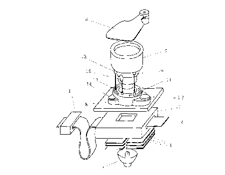
Fig. 1 shows a photographic printing apparatus
according to an embodiment of the present invention. This
printing apparatus is composed of a lens unit and a lens
mount. The lens unit has a variable aperture and a variable
focal distance. The lens mount includes drive motors and a
drive force transmitting mechanism to change the aperture
and focal distance of the lens unit.
Numeral 1 denotes a scanner which serves as a means for
computing exposure conditions based on information of the
image to be printed. The scanner 1 captures an image on a
negative film 2 and obtains image information necessary for
printing, such as the kind of film, size and density of the
image, and balance of colors. Also, a printing
magnification is determined taking account of the width of
21~7732
printing paper which is detected by an unillustrated width
sensor.
Light from an exposure light source 3 is regulated by
an automatic light regulator 4 such that the light with a
quality corresponding to exposure conditions is obtained.
This makes it possible to optimally reproduce colors on the
printing paper. While the film passes through a film mask
5, light having a regulated quality is irradiated to each
frame of the film. The light passing through each frame of
the film reaches the printing paper via a shutter 6 and a
lens unit 7. The length of time for exposure is controlled
by the shutter 6. The printing paper is subsequently fed to
a developing section.
The lens unit 7 used in this embodiment is a zoom lens
which includes a set of lenses, a focal distance ad;usting
mechanism and an aperture adjusting mechanism. The focal
distance and aperture of the lens unit 7 are controlled by
motors via a drive force transmitting mech~nism which are
built in a lens mount 8. The drive force transmitting
mechanism of the lens mount 8 has a structure such that it
is separably engaged with the lens unit 7.
In detail, the lens unit 7 is provided with a focal
distance adjusting jack 9 connected to the focal distance
adjusting mechanism and an aperture adjusting jack 10
connected to the aperture adjusting mechanism. The jack 9
serves as a first external connection member for adjusting
the focal distance of the lens unit 7 to vary the printing
2147732
magnification. The jack 10 serves as a second external
connection member for adjusting the aperture of the lens
unit 7 to vary the amount of light for printing.
The focal distance adjusting jack 9 is connected to a
focal distance adjusting pin 11 when the lens unit 7 is
attached to the lens mount 8. When the pin 11 is moved by a
focus adjusting motor 12, its movement is transmitted to the
jack 9, so that the focal distance of the lens unit 7 is
adjusted.
The aperture adjusting jack 10 is connected to an
aperture adjusting pin 13 when the lens unit 7 is attached
to the lens mount 8. When the pin 13 is moved by an
aperture adjusting motor 14, its movement is transmitted to
the jack 10, so that the aperture of the lens unit 7 is
adjusted. A positioning key 15 is provided on the lens unit
7 to position the lens unit 7 with respect to the lens mount
8, thereby providing accurate alignment between the pins and
jacks.
Fig. 2 shows a mechanism for holding the lens unit 7 in
the lens mount 8. When the lens unit 7 is inserted into the
lens mount 8, a cam surface formed on the positioning key 15
of the lens unit 7 engages with a holding roller 17 which is
forced by a holding spring 16 to swing inward. The
positioning key 15 moves the holding roller 17 outward while
rotating it, and reaches a predetermined mount position at
which the lens unit 7 is held by the holding roller 17.
Next, a photographic printing apparatus according to
214773~
another embodiment of the present invention will be
described with reference to Figs. 3 and 4. This printing
apparatus is composed of a plurality of lens units having
different focal distances and a lens mount. The aperture
and focal distance of a lens unit selectively attAc~e~ to
the lens mount is controlled by drive motors which are
provided in the lens mount.
Lenses 18, 19 and 20 are attached to a turntable 21
along a circle centered at the rotational axis of the
turntable 21. The rotational axis (screw shaft 22) of the
turntable 21 is parallel to the optical axis of the printing
apparatus, and the turntabIe 21 is moved upward and downward
in the direction parallel to the rotational axis.
The joint portions of each lens unit and the lens mount are
provided with pins and jacks similar to those shown in Fig.
1. These pins and jacks serve as a driving force
transmitting means for varying the aperture and focal
distance of a selected lens unit. Instead of the pins and
jacks, gears may be used as the driving force transmitting
means.
The turntable 21 is arranged above a lens mount 25. A
drive motor 23 is provided for rotating an unillustrated
drive roller which is contacted with the peripheral surface
of the turntable 21 with pressure. Another drive motor 24
is provided to rotate the screw shaft 22; To remove a lens
unit from the lens mount 25, the screw shaft 22 is rotated
by the drive motor 24 so that the turntable 21 is elevated.
21~7732
The drive roller is vertically moved synchronously with the
vertical movement of the turntable 21 so that the drive
roller always contacts the turntable 21. Also, when the
turntable 21 is vertically moved, the drive motor 23 is
controlled to act as a brake for preventing the rotation of
the turntable 21. Subsequently, the turntable 21 is rotated
such that a lens unit 18 re~chec a predetermined position
above the lens mount 25.
The turntable 21 is then lowered to insert the selected
lens unit 18 into the lens mount 25 for connection
therewith. Thereafter, the next printing operation is
started.
After the attachment of the lens unit 18, a focal
distance adjusting pin 26 and an aperture adjusting pin 27
of the lens mount 25 are moved by motors. As a result, the
focal distance adjusting jack and aperture adjusting jack of
the lens unit 18 are moved to adjust the focal distance and
the aperture in accordance with a printing magnification.
When the lens unit 18 is exchanged, the turntable 21 is
again elevated and rotated to select the next designated
lens unit. This operation is repeated.
Next, a method for identifying the kind of lens units
will be described. As shown in Fig. 4, the identification
is made by detecting an identification mark provided on each
lens unit. In the present embodiment, holes are used as a
mark. When a lens unit 28 is attached to the lens mount 25,
a lens unit identification member 30 of the lens unit 28 is
2147732
inserted into a groove of a lens identifying device 31
provided in the vicinity of the lens mount 25.
Holes 32, 33 are formed in the lens identification
member 30. Sensors 34, 35 and 36 are provided in the lens
identifying device 31 at positions where the sensors face
the holes. In the present embodiment, five kinds of lens
units are identified using three sensors. In detail,
sensors 34, 35 and 36 of the lens identifying device 31 are
stacked in the vertical direction to detect the presence of
holes in the lens identification member 30 so as to judge
the focal distance of a lens unit attached to the lens mount
25. Fig. 5 shows the relationship between output signals of
the sensors and the kinds of lens units.
Obviously, numerous modifications and variations of the
present invention are possible in light of the above
teachings. It is therefore to be understood that within the
scope of the appended claims, the present invention may be
practiced other than as specifically described herein.