Language selection

Search

Patent 2147899 Summary

Third-party information liability

Some of the information on this Web page has been provided by external sources. The Government of Canada is not responsible for the accuracy, reliability or currency of the information supplied by external sources. Users wishing to rely upon this information should consult directly with the source of the information. Content provided by external sources is not subject to official languages, privacy and accessibility requirements.

Claims and Abstract availability

Any discrepancies in the text and image of the Claims and Abstract are due to differing posting times. Text of the Claims and Abstract are posted:

  • At the time the application is open to public inspection;
  • At the time of issue of the patent (grant).
(12) Patent: (11) CA 2147899
(54) English Title: SAW BLADE DRIVE SYSTEM
(54) French Title: SYSTEME D'ENTRAINEMENT DE LAME DE SCIE
Status: Expired and beyond the Period of Reversal
Bibliographic Data
(51) International Patent Classification (IPC):
  • B27B 9/00 (2006.01)
  • B23D 61/02 (2006.01)
  • B27B 5/32 (2006.01)
  • B27B 11/00 (2006.01)
(72) Inventors :
  • TAYLOR, GARY R. (Canada)
  • WIERZBA, PAUL (Canada)
(73) Owners :
  • BALANCE INVESTMENTS LTD.
(71) Applicants :
  • BALANCE INVESTMENTS LTD. (United Kingdom)
(74) Agent: BLAKE, CASSELS & GRAYDON LLP
(74) Associate agent:
(45) Issued: 1998-01-27
(22) Filed Date: 1995-04-26
(41) Open to Public Inspection: 1996-10-27
Examination requested: 1996-02-13
Availability of licence: N/A
Dedicated to the Public: N/A
(25) Language of filing: English

Patent Cooperation Treaty (PCT): No

(30) Application Priority Data: None

Abstracts

English Abstract


A sawblade and a drive spline having a drive
configuration therebetween. The drive configuration
comprises inner driven surfaces on the sawblade which are
driven by the drive spline which has outer drive recesses
complementary to the inner driven surfaces of the
sawblade. First and second radials extend outwardly from
the axis of rotation of the drive spline and sawblade.
They extend so as to contact the ends of a respective
recess or drive surface most closely located to the axis
of rotation. Second and third radials extend to contact
the ends of the most remotely located recess or drive
surface. The angular distance between the first and
second radials is greater than the angular distance
between the third and fourth radials.


French Abstract

Lame et cannelure d'entraînement ayant une configuration spécifique. La lame comprend des surfaces entraînées internes, lesquelles sont actionnées par une cannelure d'entraînement dotée de creux d'entraînement externes complémentaires aux surfaces entraînées internes de la lame. Une première et une deuxième lignes radiales rayonnent vers l'extérieur par rapport à l'axe de rotation de la cannelure d'entraînement et de la lame. Les lignes radiales se prolongent jusqu'à ce qu'elles atteignent les extrémités d'un creux ou d'une surface d'entraînement située plus près de l'axe de rotation. Une troisième et une quatrième lignes radiales se prolongent de manière à entrer en contact avec le creux ou la surface d'entraînement la plus éloignée. La distance angulaire entre les première et deuxième lignes radiales est supérieure à la distance angulaire entre les troisième et quatrième lignes radiales.

Claims

Note: Claims are shown in the official language in which they were submitted.

- 8 -
THE EMBODIMENTS OF THE INVENTION IN WHICH AN EXCLUSIVE
PROPERTY OR PRIVILEGE IS CLAIMED ARE DEFINED AS FOLLOWS:
1. A sawblade of circular configuration having an axis
of rotation, an outer cutting edge and a plurality
of inner driven surfaces defined by a first angular
distance between a first and second radial, said
first and second radials contacting each end of a
respective one of said driven surfaces located most
closely to said axis of rotation, and a second
angular distance between a third and fourth radial,
said third and fourth radials contacting each end of
said respective one of said driven surfaces located
most remotely from said axis of rotation, the
angular distance between said first and second
radials being greater than the angular distance
between said third and fourth radials.
2. A drive spline of circular configuration having an
axis of rotation, a plurality of outer drive
recesses defined by a first angular distance between
a first and second radial, said first and second
radials contacting each end of a respective one of
said drive recesses located most closely to said
axis of rotation and a second angular distance
between a third and fourth radial, said third and
fourth radials contacting each end of a respective
one of said drive recesses located most remotely
from said axis of rotation, the angular distance
between said first and second radial, being greater
than the angular distance between said third and
fourth radials.
3. A drive spline as in claim 2 wherein said drive
recesses contain removable inserts which form drive
surfaces on said spline.

- 9 -
4. A drive spline as in claim 3 wherein said removable
inserts are made of hardened steel material.

Description

Note: Descriptions are shown in the official language in which they were submitted.


- 21~7899
SAW BLADE DRIVIS SYST13M
INTROL~ LlON
This invention relates to a saw blade and a
drive system therefore and, more particularly, to a
sawblade and its associated drive spline having a
specific driving configuration.
RACK~ROUND OF THE lNv~NllON
Circular type sawblades to cut cants or lumber
are, of course, known together with their associated
drive splines. Typically, the drive spline has a series
of rounded or convex male drive pieces spaced
intermittently and circumferentially around the drive
spline. They mate with correspo~; ng concave female
recesses in the saw blade. Typically, the sawblade is
mounted onto the drive ~pline endwise. It slides over
the spline until the desired operating position on the
drive spline is reached. Under operating conditions, the
sawblade is maintained in its desired position with
sawguides which prevent undesirable movement in the
sawblade. This keeps the kerf or cutting width created
by the blade narrow which i~ desirable in order not to
avoid wood wastage during the sawing operation.
The drive spline used with the aforementioned
convex male driving pieces has problems. Such problems
relate to safety, tolerances and sawblade driving
efficiency.
In respect of the former, there has arisen the
unfortunate practise of "tree spiking" by those
protective of logs which they feel should not be felled.
This practise involves driving large nails or spikes into

- 21~7~99
the trunks of trees before cutting. Often the spikes are
not readily observed by either the fellers or the sawmill
operators with the result that during sawmill operations,
the sawblade may strike a spike within the cant or log
during the cutting operation. This i8 a most dangerous
occurrence since the sawblade can tear or fragment and
pieces of shrapnel are distributed at high energy levels
throughout the area where the cutting is tAk;ng place.
This disintegration takes place because there is no
retention of the sawblade by the spline when the sawblade
splits or tears after contact with the spike. Sawmill
operators lives have been lost and their injuries have
been severe because of these tree spiking practises. It
would be advantageous if the sawblade did not tear away
from the drive spline under such conditions.
Yet a further disadvantage with present
sawblades and the convex type drive splines relates to
operating tolerances. Because of the convex type drive
spline which mates with correspo~;ng type recesses in
the sawblade, a series of point contacts occurs when the
two curved surfaces meet. This point contact results in
a series of high stress points between the drive spline
and the sawblade which increases wear on both members and
reduces the driving efficiency between the spline and the
sawblade.
Yet a further disadvantage with the present
sawblade-drive spline system is that the position of the
sawblade on the drive spline can change during operation.
This is 80 because there are tolerances between the
convex drive surfaces of the drive spline and the concave
driven surfaces of the sawblade. The saw blade will move
upwardly and downwardly on the spline during operation
while various impact loadings occur and the sawblade
moves upwardly and downwardly on the spline through these

- 2147899
tolerances. Thus, the actual driving efficiency is
adversely affected.
Yet a further disadvantage with the present
drive spline design is the fact that the spline has to be
hardened to a hardness greater than that of the blade.
This practise is time consuming and expensive.
SUMMARY OF THE lNv~NllON
According to one aspect of the invention,
there is provided a sawblade of circular configuration
having an axis of rotation, an outer cutting edge and a
plurality of inner driven surfaces defined by a first
angular distance between a first and second radial, said
first and second radials contacting each end of a
respective one of said driven surfaces located most
closely to said axis of rotation, and a second angular
distance between a third and fourth radial, said third
and fourth radials contacting each end of ~aid respective
one of said driven surfaces located most remotely from
said axis of rotation, the angular distance between said
first and second radials being greater than the angular
distance between said third and fourth radial~.
According to a further aspect of the invention,
there is provided a drive spline of circular
configuration having an axis of rotation, a plurality of
outer drive recesses defined by a first angular distance
between a first and second radial, said first and second
radials contacting each end of a respective one of said
drive recesses located most closely to said axis of
rotation and a second angular distance between a third
and fourth radial, said third and fourth radials
contacting each end of a respective one of said drive
recesses located most remotely from said axis of

'- 2147899
rotation, the angular distance between said first and
second radials being greater than the angular di~tance
between ~aid third and fourth radial~.
According to a further aspect of the invention,
there is provided a drive spline of circular
configuration having an axis of rotation, said drive
spline having a plurality of drive recesses having
replaceable drive surfaces along first angular distance
between a first and second radial, said drive surfaces
ext~n~;ng axially along said drive spline.
BRIEF DESCRIPTION OF THE SEVERAL VIEWS OF THE DRAWINGS
A specific embodiment of the invention will now
be described, by way of example only, with the use of
drawings in which:
Figure 1 is a side diagrammatic view of a
circular sawblade mounted on a drive spline which, in
turn, is mounted on an arbor, the sawblade and drive
~pline having a configuration according to the invention;
Figure 2 is a side diagrammatic enlarged view
of a circular sawblade mounted on a drive spline and
illustrating the drive configuration between the spline
and the sawblade according to a first embodiment of the
invention;
Figure 3 is an enlarged view of the circular
~awblade of Figure 2;
Figure~ 4A, 4B, 4C and 4D are enlarged views of
four different drive spline configurations according to a
further aspect of the invention; and

2147899
Figure 5 is an enlarged view of an insert
according to a further aspect of the invention.
DESCRIPTION OF SPECIFIC EMBODIMENT
Referring now to the drawings and, more
particularly, to Figure 1, a circular ~awblade 10 i8
mounted on a drive spline 11 which, in turn, is mounted
on an arbor 12. Arbor 12 is journalled in bearings 13
and a source of turning power for the arbor 12 is
provided (not shown) which is then transferred to the
sawblade 10 to turn the sawblade 10 and cut the wood
diagrammatically illustrated at 14. A pair of sawguides
20 are mounted on either side of the circular sawblade
10. They guide the sawblade 10 and can move it axially
on the drive spline 11. It will be appreciated, of
course, that a plurality of sawblades could be mounted on
the drive spline 11 depen~; ng on the lumber which is
being cut and the desire~ of the operator.
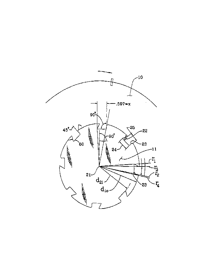
Reference is now made to Figure 2 which
illustrates the sawblade 10 mounted on the drive spline
11. The drive spline 11 and sawblade 10 have a common
axis of rotation 21 and, under operation, the sawblade 10
rotates clockwise as seen by the arrows. A ~eries of
inner driven surfaces 22 of sawblade 10 are complementary
to outer drive rece~ses 23 of drive spline 11. The inner
distance 24 of drive surface 22 is greater that the outer
distance 25 such that if the sawblade contacts a foreign
object such a spike in a tree being cut, the blade 10
will not be hurled from the drive spline 11 but will be
ret~; ne~ by the drive spline 11 such that the operator
may immediately terminate operation of the drive system.
More particularly, the out~ide circumference of
the drive spline is indicated by first diameter dio and

2147899
the inside diameter of the drive spline is indicated by
second diameter d2i. The distance between dio and d2i is
the distance between the outer diameter of the drive
spline 11 and the most inwardly distance of the drive
5 recess 23.
First and second radials r1, r2 are drawn from
the axis of rotation 21 to touch the ends of the drive
recess 23 located most closely to axis 21. Third and
10 fourth radials r3, r4 are drawn from the axis of rotation
21 to touch the ends of the drive recess 23 located most
remotely from axis 21. The angular distance between rl
and r2 will be larger than the distance between r3 and r4
as can clearly be seen from Figures 2 and 3.
For example, in a first embodiment of the
invention as illustrated in Figure 2, the distance
between the ends of the drive recess 23 located closest
to axis 21 is . 597 in. as illustrated. This di~tance is
20 obtained by drawing radials to each of the ends of the
drive recess 23 and measuring the distance of . 597. A 60
degree angle is cut into the drive spline 23 and a
surface is formed 90 degrees to the line defining the
distance of . 597 in. which meets the 60 degree angle cut.
This surface defines the most advanced point of the
radial rl and the most retarded point of radial r2.
It will be readily seen that a number of
different configurations for the drive recesses 23 of
drive spline 11 and the drive surfaces 22 of sawblade 10
could be used in order to achieve the benefits of the
present invention. Reference is made, for example, to
Figures 4A, 4B, 4C and 4D.
In Figure 4A, drive surfaces 30 take a somewhat
partially convex configuration and in Figure 4B, drive

21~7899
surfaces 32 take on an appearance similar to the drive
surfaces 22 of Figures 2 and 3 but extend inwardly a much
greater distance. However, it remains the case that the
angular distance e1 between the radials r1, r2 is less
that the angular distance e2 between the radials r3, r4.
Figures 4C and 4D illustrate two further drive
configurations according to further aspects of the
invention. In each of these configurations, there is a
drive surface 40, 41 which has an angle ~ relative to
radial r3 which is greater than zero degrees. Thus, there
will be a partial ret~;n;ng effect executed on the
sawblade 43 by the forces executed between drive surfaces
41, 42 of the spline by the sawblade.
In Figure 5, replaceable drive surfaces 34 are
located along removable inserts made of hardened steel
material 35 ext~n~;ng axially along the spline 11, and
being secured to the drive spline with bolts 36.
While specific embodiments of the invention
have been described, such descriptions should be taken as
illustrative of the invention only and not as limiting
its scope as defined in accordance with the accompanying
claims.

Representative Drawing
A single figure which represents the drawing illustrating the invention.
Administrative Status

2024-08-01:As part of the Next Generation Patents (NGP) transition, the Canadian Patents Database (CPD) now contains a more detailed Event History, which replicates the Event Log of our new back-office solution.

Please note that "Inactive:" events refers to events no longer in use in our new back-office solution.

For a clearer understanding of the status of the application/patent presented on this page, the site Disclaimer , as well as the definitions for Patent , Event History , Maintenance Fee  and Payment History  should be consulted.

Event History

Description Date
Inactive: IPC from MCD 2006-03-11
Inactive: Inventor deleted 2001-06-06
Time Limit for Reversal Expired 2001-04-26
Letter Sent 2000-04-26
Inactive: Late MF processed 1999-10-19
Letter Sent 1999-04-26
Letter Sent 1998-06-15
Grant by Issuance 1998-01-27
Inactive: Adhoc Request Documented 1997-11-25
Inactive: Adhoc Request Documented 1997-11-24
Inactive: Final fee received 1997-10-16
Pre-grant 1997-10-16
Letter Sent 1997-08-14
Notice of Allowance is Issued 1997-08-14
Inactive: Status info is complete as of Log entry date 1997-08-11
Inactive: Application prosecuted on TS as of Log entry date 1997-08-11
Inactive: Approved for allowance (AFA) 1997-07-31
Deemed Abandoned - Failure to Respond to Maintenance Fee Notice 1997-04-28
Inactive: Adhoc Request Documented 1997-04-28
Application Published (Open to Public Inspection) 1996-10-27
Request for Examination Requirements Determined Compliant 1996-02-13
All Requirements for Examination Determined Compliant 1996-02-13

Abandonment History

Abandonment Date Reason Reinstatement Date
1997-04-28

Fee History

Fee Type Anniversary Year Due Date Paid Date
Final fee - small 1997-10-16
Reversal of deemed expiry 1999-04-26 1998-04-24
MF (patent, 3rd anniv.) - small 1998-04-27 1998-04-24
Reversal of deemed expiry 1999-04-26 1998-04-27
MF (patent, 4th anniv.) - small 1999-04-26 1998-04-27
Owners on Record

Note: Records showing the ownership history in alphabetical order.

Current Owners on Record
BALANCE INVESTMENTS LTD.
Past Owners on Record
GARY R. TAYLOR
PAUL WIERZBA
Past Owners that do not appear in the "Owners on Record" listing will appear in other documentation within the application.
Documents

To view selected files, please enter reCAPTCHA code :


To view images, click a link in the Document Description column. To download the documents, select one or more checkboxes in the first column and then click the "Download Selected in PDF format (Zip Archive)" or the "Download Selected as Single PDF" button.

List of published and non-published patent-specific documents on the CPD .

If you have any difficulty accessing content, you can call the Client Service Centre at 1-866-997-1936 or send them an e-mail at CIPO Client Service Centre.


Document
Description 
Date
(yyyy-mm-dd) 
Number of pages   Size of Image (KB) 
Description 1996-10-26 7 256
Abstract 1996-10-26 1 21
Drawings 1996-10-26 5 72
Claims 1996-10-26 2 44
Drawings 1997-07-15 4 60
Claims 1997-07-15 1 54
Representative drawing 1998-01-20 1 4
Representative drawing 1998-02-24 1 12
Commissioner's Notice - Application Found Allowable 1997-08-13 1 164
Maintenance Fee Notice 1999-05-24 1 179
Late Payment Acknowledgement 1999-10-27 1 171
Maintenance Fee Notice 2000-05-23 1 178
Correspondence 1997-10-15 2 56
Correspondence 1998-06-14 3 80
Fees 1998-04-26 1 38
Fees 1999-10-18 1 44
Fees 2016-11-28 1 39
Prosecution correspondence 1995-04-25 17 528
Prosecution correspondence 1996-02-12 10 276
Correspondence related to formalities 1996-02-12 1 31
Courtesy - Office Letter 1996-02-19 1 16
Courtesy - Office Letter 1996-04-17 1 73
Correspondence related to formalities 1996-04-08 2 37
Correspondence related to formalities 1996-06-03 4 112
Courtesy - Office Letter 1996-07-21 1 20
Courtesy - Office Letter 1996-07-04 1 16
Prosecution correspondence 1997-06-23 4 183
Examiner Requisition 1996-12-23 2 81
Prosecution correspondence 1996-11-13 3 110
Prosecution correspondence 1996-11-13 2 62
Prosecution correspondence 1996-11-06 19 561
Prosecution correspondence 1996-11-06 1 49
Examiner Requisition 1996-05-06 2 81