Language selection

Search

Patent 2147909 Summary

Third-party information liability

Some of the information on this Web page has been provided by external sources. The Government of Canada is not responsible for the accuracy, reliability or currency of the information supplied by external sources. Users wishing to rely upon this information should consult directly with the source of the information. Content provided by external sources is not subject to official languages, privacy and accessibility requirements.

Claims and Abstract availability

Any discrepancies in the text and image of the Claims and Abstract are due to differing posting times. Text of the Claims and Abstract are posted:

  • At the time the application is open to public inspection;
  • At the time of issue of the patent (grant).
(12) Patent: (11) CA 2147909
(54) English Title: TELECOMMUNICATIONS DISTRIBUTION FRAME WITH TRACING
(54) French Title: REPARTITEUR A LOCALISATION POUR LES TELECOMMUNICATIONS
Status: Deemed expired
Bibliographic Data
(51) International Patent Classification (IPC):
  • H04Q 1/14 (2006.01)
  • G02B 6/43 (2006.01)
  • G02B 6/44 (2006.01)
  • H04B 10/00 (2006.01)
  • H04Q 1/18 (2006.01)
(72) Inventors :
  • LEONE, FRANK SALVATORE (United States of America)
  • PIMPINELLA, RICHARD JOSEPH (United States of America)
(73) Owners :
  • AT&T CORP. (United States of America)
(71) Applicants :
(74) Agent: KIRBY EADES GALE BAKER
(74) Associate agent:
(45) Issued: 1999-03-16
(22) Filed Date: 1995-04-26
(41) Open to Public Inspection: 1995-12-10
Examination requested: 1995-04-26
Availability of licence: N/A
(25) Language of filing: English

Patent Cooperation Treaty (PCT): No

(30) Application Priority Data:
Application No. Country/Territory Date
255,621 United States of America 1994-06-09

Abstracts

English Abstract


Disclosed is a distribution unit which provides means for tracing patch
connections. Each module is electrically connected to a shelf controller through a
backplane. The shelf controllers are, in turn, coupled to a host computer. Pressing a
button on one module lights an LED on that module and on the module which shouldbe connected thereto based on the data base in the host computer.


French Abstract

L'invention est une unité de distribution qui permet de suivre les connexions de raccordement. Chaque module est électriquement connecté à un contrôleur par l'intermédiaire d'un fond de panier. Les contrôleurs sont à leur tour connectés à un ordinateur hôte. Quand on appuie sur un bouton sur l'un des modules, une diode luminescente s'allume sur ce module et sur celui qui devrait y être connecté d'après la base de données conservée dans l'ordinateur hôte.

Claims

Note: Claims are shown in the official language in which they were submitted.


-5-

Claims:

1. A telecommunications distribution frame comprising:
a plurality of shelves;
a plurality of modules within each shelf for connecting a cable to jumper cablesmeans comprising a backplane including buses for electrically connecting each
module to a host computer which includes a data base of which modules should be
connected together by a jumper cable;
means associated with a first module for directing a first signal to said host
computer through said backplane to locate a second module to be connected thereto,
means associated with the first and second modules for receiving a second
signal from the host computer through said backplane, and for visually indicating that the
second signal has been received;
whereby the said modules are identified by such visual indications.

2. Apparatus according to claim 1 wherein the modules optically connect optical
fibers from a cable to optical fiber jumper cables.

3. Apparatus according to claim 1 wherein the means for directing a signal
comprises a push-button on a front surface of the module.

4. Apparatus according to claim 1 wherein the means for visually indicating that
the signal has been received from the host computer comprises a light emitting device on
a front surface of the modules.

5. Apparatus according to claim 1 wherein the means for connecting each module
to the host computer comprises busses on a backplane and controllers coupled to
corresponding shelves of panels.

6. Apparatus according to claim 5 wherein the controllers coupled to each shelf are
coupled to the host computer by means of a local area network bus.


-6-

7. A module for connecting a cable to a jumper cable comprising:
means for signalling a host computer coupled to the module through a
backplane, which host computer includes information as to where the module should be
connected; and
visual means for indicating that said signal has been sent to and received from
the host computer through the backplane.

8. Apparatus according to claim 7 wherein the indicating means is a light emitting
device.

9. Apparatus according to claim 7 wherein the means for signalling comprises a
push-button on the front surface of the module.

10. Apparatus according to claim 7 wherein the module is adapted for optically
connecting fibers in the cable to optical fiber jumper cables.

Description

Note: Descriptions are shown in the official language in which they were submitted.


~ 7 9 ~ 9
..~

,

TELECOMMUNICATIONS DISTRIBUTION FRAME WITH TRACING

Back~round of the Invention
This invention relates to telecommunicationsequipment such as optical fiber
distribution frames.
Optical fiber distribution frames, such as AT&T's lightguide cross-connect
(LGX~) distribution frame, serve the function of coupling incoming fiber optic cables to
customer equipment. The frame typically includes a multiplicity of shelves, each shelf
including a single or plurality of modules where the optical connections are made to the
fibers of the incoming cable. Cross-connect jumper cables (also known as patch cords)
are applied in the front of the apparatus between the panels which are opticallyconnected(see, e.g., U.S. Pat. No. 4,630,886).
One of the problems which exists in typical frames is the high density of optical
connections, typically 72-144 connections per shelf. The great number of cross-
connections makes it very difficult to be able to determine if both ends of a jumper cable
are properly connected.
In order to trace the fiber connections, it has been proposed to provide at one
end of each jumper cable a light source which launches a light signal through the fiber
jacket to light both ends of the jumper (see, e.g., U.S. Pat. No. 5,305,405).
It is desirable to have an optical fiber distribution frame which gives an
indication of where the fiber jumper cables should be connected, either for purposes of
making the connection, or once the connection is made, to be able to tell where the
opposite ends of a particular cable are connected. It is desirable to do this without an
active light source involved in the tracing.
Summarv of the Invention
The invention is a telecommunicationsdistribution frame having a plurality of
shelves, each shelf including a plurality of modules for connecting a cable with jumper
cables. The frame includes means for electrically connecting each module to a host
computer which includes a data base indicating which modules are to be connected by a
jumper cable. Means associated with a first module to direct a first signal to the host
computer to locate a second module to be connected thereto. Means associated with said
first and second modules are provided for receiving a second signal from the host
computer and for visually indicating that said second signal has been received from the
host computer so that a visual indication is present on the two modules to be connected
by a jumper cable.

2147909


Brief Description of the Drawin~
These and other features of the invention are delineated in detail in the
description to follow. In the drawing:
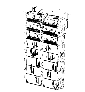
FM. 1 is a perspective view of a fiber distribution frame inr,l~ll1ing the
5 invention in accordance with one embodiment;
FM. 2 is a more detailed view of two modules which are part of the
fiber distribution frame of FIG. l;
FIG. 3 is a schematic block diagram illustrating el~ctrir~l connection
between modules of the frame in accordance with an embodiment of the invention;
10 and
FIG. 4 is a schematic block diagram illustrating further details in the
electriç~l connections in accordance with the same embodiment.
Detailed Description
FIG. 1 illustrates a typical fiber distribution frame 10 which may utilize
15 the invention. The frame inc]lldes a plurality of shelves, e.g., 11 and 14, arranged in
two columns in this example. Each shelf includes a plurality of modules, e.g., 18
and 19, where optical fibers from a trunk cable 12, or tr~n~mi~sion cable 13, are
connected with jumper fiber cables, e.g., 15, for purposes of cross-connection
between the cables. Typically, the trunk cable 12 or tr~n~mi~sion cable 13 is brought
20 into the frame at the back and fibers from the cable are introduced into each module
through an a~l Lulc which can be located at the front or rear of the shelves. In this
example, all fiber connections are made in the front of the module.
For purposes of illustration, the doors of the top three shelves in each
column have been removed. Again, for purposes of illustration, a set of jumper
25 cables, e.g. lS, are shown connected from shelf 11 (e.g., module 18) through
a~.~ 16 to shelf 14 (e.g., module 19) through apellule 17. Of course, any fiberfrom the trunk cable 12 can be connected with any fiber from the transmission cable
13 through an applu~liate jumper cable connection. In this example, each of the
shelves in the left-hand column has access to the trunk cable and each of the shelves
30 in the right-hand column has access to the tr~n~mi~sion cable, but other
arrangements are possible.
It will be appreciated that the invention is also applicable for frames
providing connections other than optical connections between cables (e.g.,
electrical).

- 21~7~09


FIG. 2 gives more detail in the two modules, 18 and 19, which are to be
optically connected by the jumper cable 15. Each panel includes a pair of jacks, 20,
21 and 30, 31, which receive standard optical connectors att~che~l to a pair of fibers
(not shown) from the trunk cable 12 in the case of module 18 or tr~n~mi~sion cable
5 13 in the case of module 19. One of the jacks (20, 30) is adapted for receiving
optical signals from a respective cable, and the other jack (21, 31) is adapted for
tr~n~mitting optical signals to its respective cable. Each panel also includes a pair of
jacks, 22, 23 and 32, 33, for optically connecting the two modules. As illustrated by
the arrows, jack 22 of module 18 will be optically coupled to jack 33 of module 19,
10 while jack 23 of module 18 will be optically coupled to jack 32 of module 19. Thus,
plugging a jumper cable into the ~plupl;ate jacks of modules 18 and 19 will provide
the necessary cross-connection between a pair of fibers from the central of fice (cable
12) and a pair of fibers coupled to a customer's equipment (cable 13).
Due to the high density of modules and jumper cables, it is often
15 difficult to find the a~lu~liate modules to be connected. In order to aid this process,
each module includes a push-button light emitting diode, 24 and 34, which will light
the al)plupliate modules to be connect~ in the manner to be described.
FIGS. 3 and 4 illustrate sch~m~ti~lly how the modules are el~qctric~lly
int~ o~-l-ectecl to provide this function. Depending upon the appli.~tion, some
mo l~ s, e.g., 18 and 19, include a microprocessor, 40 and 41, electrically connected
to the push-button LED, 24 and 34, on the front surface of the module. Some
modules, e.g., 25, may not include a microprocessor. In either case, the push-button
LEDs (e.g., 24 and 26 of FIG. 4) in each module in a shelf are elec~rir~lly coupled to
a backplane which includes a bus, e.g., 42 and 43. The bus couples the modules in a
shelf through a programmable logic chip 27 to a shelf controller, e.g., 44 and 45,
which is usually contained on a separate printed circuit card at the end of the shelf.
Each shelf controller is coupled via a bus, 46 or 47, on the backplane to a bay
controller (BC) router, 48 or 49, which, in turn, is coupled to a local area network
bus 50 such as are found in Echelon networks.
The bus 50 is electrically coupled through an interf~ce 51 to a host
CO~lput~,, 52. The host co",l)ute. 52 has stored therein all the permissible optical
connections between modules which are electrically connected to the host throughbus 50.
Thus, for example, if a cl~L~lson desires to optically connect module
18 to its permissible mate (module 19), he or she would press the push-button 24a
which is part of the push-button LED 24 on the front surface of the module 18. The

2147909
.~ .


depression of the button completes an electrical connection to the backplane bus 42
and thereby signals the shelf controller 44 through chip 27 that a connectiQn is to be
made to the module 18. The shelf controller has stored therein the addresses of each
module on that shelf and, so, can identify which module is seeking a connection.S The shelf controller sends this information to the host 52 which, as previously stated,
has the pçrmi~sikle connections for all the modules. The host, therefore, sends
meSs~s to both shelf controllers 44 and 45 connecte~ to modules 18 and 19,
r~ ely. The messages tell the shelf controllers to light the LEDs (e.g., 24b) onthe front of modules 18 and 19.
The c~ cl~on now has a visual indication on the front of the modules
which are to be connected and can apply the jumper cables to those modules. Thissame procedure can also be followed if the optical connections already exist and the
claf~elson looking at one end of a jumper cable wants to know where the other end
of the jumper cable is connected.
When it is desired to turn the LEDs off, the clafl~l el~on can press the
button, e.g., 24a, on either of the modules 18 or 19, and this will signal the host to
send another signal to the shelf controller to turn off the lights on modules 18and 19.
It should be appreciated that, while the push-button LEDs are preferably
20 located on the front surfaces of the modules, they could also be located somewhere
else in the frame with a proper in~ic~tion of which LED is associated with whichpanel.

Representative Drawing
A single figure which represents the drawing illustrating the invention.
Administrative Status

For a clearer understanding of the status of the application/patent presented on this page, the site Disclaimer , as well as the definitions for Patent , Administrative Status , Maintenance Fee  and Payment History  should be consulted.

Administrative Status

Title Date
Forecasted Issue Date 1999-03-16
(22) Filed 1995-04-26
Examination Requested 1995-04-26
(41) Open to Public Inspection 1995-12-10
(45) Issued 1999-03-16
Deemed Expired 2003-04-28

Abandonment History

There is no abandonment history.

Payment History

Fee Type Anniversary Year Due Date Amount Paid Paid Date
Application Fee $0.00 1995-04-26
Registration of a document - section 124 $0.00 1995-11-16
Maintenance Fee - Application - New Act 2 1997-04-28 $100.00 1997-02-21
Maintenance Fee - Application - New Act 3 1998-04-27 $100.00 1998-02-27
Final Fee $300.00 1998-12-01
Maintenance Fee - Patent - New Act 4 1999-04-26 $100.00 1999-03-30
Maintenance Fee - Patent - New Act 5 2000-04-26 $150.00 2000-03-20
Maintenance Fee - Patent - New Act 6 2001-04-26 $150.00 2001-03-19
Owners on Record

Note: Records showing the ownership history in alphabetical order.

Current Owners on Record
AT&T CORP.
Past Owners on Record
LEONE, FRANK SALVATORE
PIMPINELLA, RICHARD JOSEPH
Past Owners that do not appear in the "Owners on Record" listing will appear in other documentation within the application.
Documents

To view selected files, please enter reCAPTCHA code :


To view images, click a link in the Document Description column. To download the documents, select one or more checkboxes in the first column and then click the "Download Selected in PDF format (Zip Archive)" or the "Download Selected as Single PDF" button.

List of published and non-published patent-specific documents on the CPD .

If you have any difficulty accessing content, you can call the Client Service Centre at 1-866-997-1936 or send them an e-mail at CIPO Client Service Centre.


Document
Description 
Date
(yyyy-mm-dd) 
Number of pages   Size of Image (KB) 
Cover Page 1999-03-09 1 55
Drawings 1995-12-10 4 103
Description 1995-12-10 4 206
Cover Page 1996-01-31 1 15
Abstract 1995-12-10 1 12
Claims 1995-12-10 2 54
Description 1998-04-01 4 208
Claims 1998-04-01 2 56
Drawings 1998-04-01 4 107
Representative Drawing 1999-03-09 1 25
Correspondence 1998-12-01 1 34
Fees 1997-02-21 1 63
Office Letter 1995-06-07 1 16
Correspondence Related to Formalities 1995-06-09 1 32
Prosecution Correspondence 1998-03-02 1 30
Prosecution Correspondence 1998-01-21 2 46
Examiner Requisition 1997-10-21 1 29
Prosecution Correspondence 1995-04-26 7 318