Language selection

Search

Patent 2147920 Summary

Third-party information liability

Some of the information on this Web page has been provided by external sources. The Government of Canada is not responsible for the accuracy, reliability or currency of the information supplied by external sources. Users wishing to rely upon this information should consult directly with the source of the information. Content provided by external sources is not subject to official languages, privacy and accessibility requirements.

Claims and Abstract availability

Any discrepancies in the text and image of the Claims and Abstract are due to differing posting times. Text of the Claims and Abstract are posted:

  • At the time the application is open to public inspection;
  • At the time of issue of the patent (grant).
(12) Patent Application: (11) CA 2147920
(54) English Title: ROLL GRINDING MACHINE
(54) French Title: MACHINE A RECTIFIER LES CYLINDRES DE LAMINOIRS
Status: Deemed Abandoned and Beyond the Period of Reinstatement - Pending Response to Notice of Disregarded Communication
Bibliographic Data
(51) International Patent Classification (IPC):
  • B24B 19/00 (2006.01)
  • B24B 5/04 (2006.01)
  • B24B 5/37 (2006.01)
  • B24B 47/02 (2006.01)
(72) Inventors :
  • ROHDE, WOLFGANG (Germany)
  • ROSENTHAL, DIETER (Germany)
  • BENDER, HANS-JURGEN (Germany)
(73) Owners :
  • SMS SCHLOEMANN-SIEMAG AKTIENGESELLSCHAFT
(71) Applicants :
  • SMS SCHLOEMANN-SIEMAG AKTIENGESELLSCHAFT (Germany)
(74) Agent: RICHES, MCKENZIE & HERBERT LLP
(74) Associate agent:
(45) Issued:
(22) Filed Date: 1995-04-26
(41) Open to Public Inspection: 1995-10-29
Examination requested: 2002-04-09
Availability of licence: N/A
Dedicated to the Public: N/A
(25) Language of filing: English

Patent Cooperation Treaty (PCT): No

(30) Application Priority Data:
Application No. Country/Territory Date
P 44 14 838.0 (Germany) 1994-04-28

Abstracts

English Abstract


A grinding machine for the rolls of a roll stand includes a
guide unit extending parallel to the roll to be ground. Mounted
on the guide unit is a grinding unit which is displaceable in
longitudinal direction of the roll by a displacement drive. The
grinding unit is adjustable relative to the roll by adjusting
drives. The guide unit is provided with a rotary drive which is
capable of rotating the guide unit about its longitudinal axis.
The grinding unit is formed by a grinding element which is
symmetrical with respect to rotation. The grinding element is
connected to the guide unit in such a way that the grinding
element and the guide unit rotate together.


Claims

Note: Claims are shown in the official language in which they were submitted.

We Claim:
1. A grinding machine for grinding a roll of a roll stand,
the grinding machine comprising a guide means having a
longitudinal axis, the guide means extending parallel to the
roll, a grinding means and a displacement drive for displacing
the grinding means in a longitudinal direction of the roll,
adjusting drives for adjusting the grinding means relative to the
roll, a rotary drive for rotating the guide means about the
longitudinal axis thereof, the grinding means comprising a
grinding element which is symmetrical with respect to rotation,
and means for connecting the grinding element to the guide means
so that the grinding element and guide means rotate together.
2. The grinding machine according to Claim 1, wherein the
guide means comprises a tubular shaft, the tubular shaft having a
slot, a drive member projecting through the slot of the tubular
shaft, the grinding element being connected to the drive member,
and wherein the displacement drive is operatively connected to
the drive member.
3. The grinding machine according to Claim 2, further
comprising a nut mounted in the tubular shaft, the nut being
operatively connected to the drive member, a spindle being
11

surrounded by the nut, wherein the spindle is connected to the
displacement drive for rotating the spindle.
4. The grinding machine according to Claim 3, wherein the
nut is a recirculating ball nut and the spindle is a threaded
spindle.
5. The grinding machine according to Claim 3, comprising a
coupling mounted between the displacement drive and the spindle.
6. The grinding machine according to Claim 1, comprising
sensors for monitoring a displacement movement of the grinding
element and for reversing the displacement drive when the sensors
respond.
7. The grinding machine according to Claim 1, comprising
oscillation-compensating elements between the rotary drive and
the guide means and between the displacement drive and the
grinding means.
8. The grinding machine according to Claim 7, wherein the
oscillation-compensating elements are toothed belts.
12

9. The grinding machine according to Claim 1, wherein the
guide means is adjustable into the roll.
10. The grinding machine according to Claim 1, comprising a
link having two arms, the guide means being mounted between the
two arms of the link, wherein the adjustment drive is operatively
connected to the link.
11. The grinding machine according to Claim 10, wherein the
roll stand comprises chocks supporting the roll, the link having
a fulcrum, the link being mounted at the fulcrum thereof in the
chocks.
12. The grinding machine according to Claim 1, wherein the
grinding machine is mounted in an exchangeable cassette and the
grinding machine and the exchangeable cassette are mounted
together in the roll stand.
13. The grinding machine according to Claim 1, wherein the
roll stand comprises chocks, the grinding machine being mounted
in an exchangeable cassette, wherein the grinding machine and the
exchangeable cassette are mounted together between the chocks.
13

Description

Note: Descriptions are shown in the official language in which they were submitted.


214792~
R~C~RO~ND OF THE lNVkNLION
1. ~ield of the Invention
The present invention relates to a grinding machine for the
rolls of a roll stand. The grinding machine includes a guide
means extending parallel to the roll to be ground. Mounted on
the guide means is a grinding means which is displaceable in
longitudinal direction of the roll by means of a displacement
drive. The grinding means is adjustable relative to the roll by
means of adjusting drives.
2. Description of the Related Art
A grinding machine of the above-described type is known, for
example, from German Patent 34 06 160. In this grinding machine,
a grinding belt is used which is placed into contact with the
roll to be ground through a complicated drive and guide unit.
The grinding belt is not an endless belt. This grinding machine
has the disadvantage that the grinding belt is quickly rolled off
from a supply roll and must subsequently be rewound in a
complicated manner or must be replaced.
Also known in the art are grinding elements which are driven
so as to rotate. However, in that case, several of these

- 2147920
grinding elements are mounted on a support, wherein a drive motor
is provided for each grinding element. The grinding elements
are driven in such a way that they oscillate over short areas
along the roll to be ground. For this purpose, it is necessary
to provide flexible electrical supply lines to the drives which
are capable of compensating for the axial movements. These
electrical supply lines are susceptible to trouble.

_ - 21~7920
S~MMARY OF THE lN V~ LIoN
Therefore, it is the primary object of the present invention
to provide a grinding machine of the above-described type which
is simple, safe and inexpensive.
In accordance with the present invention, the guide means is
provided with a rotary drive which is capable of rotating the
guide means about its longitudinal axis. The grinding means is
formed by a grinding element which is symmetrical with respect to
rotation. The grinding element is connected to the guide means
in such a way that the grinding element and the guide means
rotate together.
As a result of the configuration according to the present
invention, it is ensured that the rotary drive for the grinding
element which is longitudinally movable on the guide means is
stationary in axial direction. In addition, several grinding
elements may be driven by one motor.
In accordance with an advantageous feature of the present
invention, the guide means is constructed as a tubular or hollow
shaft, the grinding means interacts with a drive member which
projects into a slot of the tubular shaft, and the displacement

- 21~7920
drive acts on the drive member. This feature provides a simple
engagement of the displacement drive with the grinding element.
In accordance with another feature, a nut which interacts
with the drive member is arranged in the hollow shaft, the nut
surrounds a spindle and the spindle is rotatable by means of the
displacement drive. This feature provides a possibility of
transposing rotations into axial displacement movements which is
particularly easy to maintain.
Another feature provides that a coupling, preferably a slip
coupling, is provided between the displacement drive and the
spindle. As a result, damage to the grinding machine is
prevented in the case that extreme operating conditions should
occur.
In accordance with another feature, sensors are provided for
monitoring the displacement movement of the grinding element,
wherein the displacement drive is reversed when the sensors
respond. These sensors, usually constructed as switches, make it
possible to reverse the axial displacement direction through a
control unit.

21~7920
In order to ensure that no irregularities caused by
malfunctions can occur during the grinding procedure, the drive
forces and displacement forces are transmitted through
oscillation-compensating elements, such as, toothed belts.
The various features of novelty which characterize the
invention are pointed out with particularity in the claims
annexed to and forming a part of the disclosure. For a better
understanding of the invention, its operating advantages,
specific objects attained by its use, reference should be had to
the drawing and descriptive matter in which there are illustrated
and described preferred embodiments of the invention.

Z147920
BRIEF DESCRIPTION OF THE DRAWING
In the drawing:
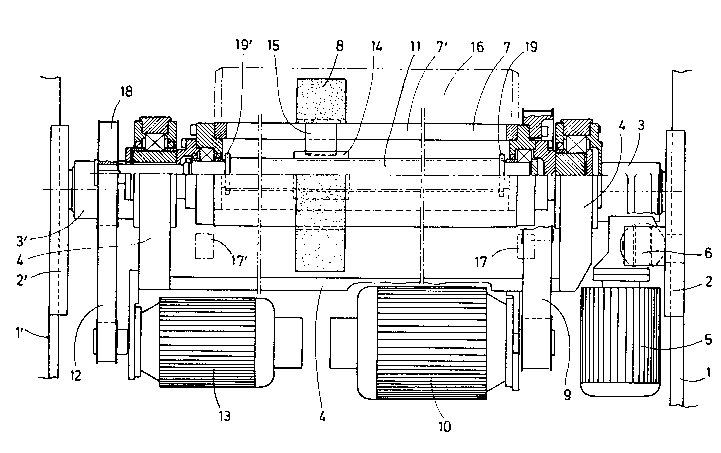
The single figure of the drawing is a schematic view,
partially in section, of a grinding machine according to the
present invention mounted in a roll stand.

2147920
DETATT.Fn DESCRIPTION OF THE PREFERRED EMBODIMENTS
The figure of the drawing shows portions of chocks 1, 1' of
a roll stand in which a changeable cassette 2, 2' is mounted.
The changeable cassette 2, 2' supports the necks 3, 3' of a link
4. An adjusting drive 5 is mounted on the changeable cassette 2
and acts on the neck 3 through a gear unit 6.
A guide member 7 is rotatably mounted in the link 4. A
grinding element 8, for example, a grinding mop, is mounted on
the guide member 7 so as to be non-rotatable, but displaceable in
axial direction. The guide member 7 is a tubular shaft 7' which
is provided with a longitudinal slot and which is drivable
through a toothed belt 9 by a rotary drive 10.
A threaded spindle 11 is mounted in the tubular shaft 7'.
The threaded spindle 11 is driven for rotation through a toothed
belt 12 by means of a displacement drive 13 which is mounted on
the link 4. A recirculating ball nut 14 is mounted on the
threaded spindle 11. The recirculating ball nut 14 is connected
to the grinding element 8 through a drive member 15 which
projects into the tubular shaft 7' in the area of the slots, not
shown, of the hollow shaft 7'.

- 21~7920
The grinding machine operates as follows:
By using the adjusting drive 15, the link 4 can be swivelled
in such a way that the grinding element 8 is adjusted relative to
the roll 16. The rotary drive 10 places in rotary motion the
guide member 7 and, thus, the grinding element 8. Simultaneously,
the displacement drive 13 drives the threaded spindle 11.
When the guide member 7 and the threaded spindle 11 are
operated at the same rate of rotation, the grinding element,
which is in operative connection through the drive member 15 and
the recirculating ball nut 14 with the threaded spindle 11,
remains in an axial position of rest. As soon as the
displacement drive 13 raises or lowers the rate of rotation of
the threaded spindle 11 relative to the rate of rotation of the
guide member 7, the recirculating ball nut 14 is displaced on the
threaded spindle 11 and, in turn, displaces the grinding element
8.
When the grinding element 8 reaches one of the ends of the
guide member 7, the grinding element is in the range of one of
the sensors 17, 17' which are constructed as switching cams.
Through a control, not shown, the sensors 17, 17' influence the

2147920
rate of rotation of the displacement drive 13 in dependence on
the rate of rotation of the rotary drive 10 in such a way that
the grinding element 8 is moved in the opposite direction.
In the event that the sensors 17, 17' switch too late or do
not switch for reasons of a defect, a collar 19 is provided at
each end of the threaded spindle 11, wherein the reciprocating
ball nut 14 rests against the collar 19, so that damage of the
support of the threaded spindle 11 and of the tubular shaft 7' is
avoided. In addition, a slip coupling 18 ensures that the
operative connection from the rotary drive 10 through the toothed
belt 9, the guide member 7, the drive member 15, the
recirculating ball nut 14, the threaded spindle 11, the toothed
belt 12 to the displacement drive 13 is not completely rigid, so
that damage to the grinding machine is avoided.
The invention is not limited by the embodiments described
above which are presented as examples only but can be modified in
various ways within the scope of protection defined by the
appended patent claims.

Representative Drawing
A single figure which represents the drawing illustrating the invention.
Administrative Status

2024-08-01:As part of the Next Generation Patents (NGP) transition, the Canadian Patents Database (CPD) now contains a more detailed Event History, which replicates the Event Log of our new back-office solution.

Please note that "Inactive:" events refers to events no longer in use in our new back-office solution.

For a clearer understanding of the status of the application/patent presented on this page, the site Disclaimer , as well as the definitions for Patent , Event History , Maintenance Fee  and Payment History  should be consulted.

Event History

Description Date
Inactive: IPC from MCD 2006-03-11
Application Not Reinstated by Deadline 2004-04-26
Time Limit for Reversal Expired 2004-04-26
Deemed Abandoned - Failure to Respond to Maintenance Fee Notice 2003-04-28
Inactive: Application prosecuted on TS as of Log entry date 2002-05-02
Letter Sent 2002-05-02
Inactive: Status info is complete as of Log entry date 2002-05-02
Request for Examination Requirements Determined Compliant 2002-04-09
All Requirements for Examination Determined Compliant 2002-04-09
Letter Sent 1998-06-17
Reinstatement Requirements Deemed Compliant for All Abandonment Reasons 1998-06-11
Deemed Abandoned - Failure to Respond to Maintenance Fee Notice 1998-04-27
Letter Sent 1997-07-02
Reinstatement Requirements Deemed Compliant for All Abandonment Reasons 1997-06-19
Deemed Abandoned - Failure to Respond to Maintenance Fee Notice 1997-04-28
Inactive: Adhoc Request Documented 1997-04-28
Application Published (Open to Public Inspection) 1995-10-29

Abandonment History

Abandonment Date Reason Reinstatement Date
2003-04-28
1998-04-27
1997-04-28

Maintenance Fee

The last payment was received on 2002-03-27

Note : If the full payment has not been received on or before the date indicated, a further fee may be required which may be one of the following

  • the reinstatement fee;
  • the late payment fee; or
  • additional fee to reverse deemed expiry.

Please refer to the CIPO Patent Fees web page to see all current fee amounts.

Fee History

Fee Type Anniversary Year Due Date Paid Date
Reinstatement 1997-06-19
MF (application, 2nd anniv.) - standard 02 1997-04-28 1997-06-19
MF (application, 3rd anniv.) - standard 03 1998-04-27 1998-06-11
Reinstatement 1998-06-11
MF (application, 4th anniv.) - standard 04 1999-04-26 1999-03-23
MF (application, 5th anniv.) - standard 05 2000-04-26 2000-03-27
MF (application, 6th anniv.) - standard 06 2001-04-26 2001-03-22
MF (application, 7th anniv.) - standard 07 2002-04-26 2002-03-27
Request for examination - standard 2002-04-09
Owners on Record

Note: Records showing the ownership history in alphabetical order.

Current Owners on Record
SMS SCHLOEMANN-SIEMAG AKTIENGESELLSCHAFT
Past Owners on Record
DIETER ROSENTHAL
HANS-JURGEN BENDER
WOLFGANG ROHDE
Past Owners that do not appear in the "Owners on Record" listing will appear in other documentation within the application.
Documents

To view selected files, please enter reCAPTCHA code :


To view images, click a link in the Document Description column. To download the documents, select one or more checkboxes in the first column and then click the "Download Selected in PDF format (Zip Archive)" or the "Download Selected as Single PDF" button.

List of published and non-published patent-specific documents on the CPD .

If you have any difficulty accessing content, you can call the Client Service Centre at 1-866-997-1936 or send them an e-mail at CIPO Client Service Centre.


Document
Description 
Date
(yyyy-mm-dd) 
Number of pages   Size of Image (KB) 
Representative drawing 1998-06-12 1 37
Cover Page 1995-04-26 1 19
Abstract 1995-04-26 1 18
Claims 1995-04-26 3 82
Drawings 1995-04-26 1 37
Description 1995-04-26 9 213
Notice of Reinstatement 1997-07-02 1 172
Courtesy - Abandonment Letter (Maintenance Fee) 1998-05-25 1 186
Notice of Reinstatement 1998-06-17 1 170
Reminder - Request for Examination 2001-12-31 1 117
Acknowledgement of Request for Examination 2002-05-02 1 179
Courtesy - Abandonment Letter (Maintenance Fee) 2003-05-26 1 176
Fees 1997-05-28 4 190
Fees 1997-06-19 1 52
Fees 1998-06-11 1 45