Language selection

Search

Patent 2148171 Summary

Third-party information liability

Some of the information on this Web page has been provided by external sources. The Government of Canada is not responsible for the accuracy, reliability or currency of the information supplied by external sources. Users wishing to rely upon this information should consult directly with the source of the information. Content provided by external sources is not subject to official languages, privacy and accessibility requirements.

Claims and Abstract availability

Any discrepancies in the text and image of the Claims and Abstract are due to differing posting times. Text of the Claims and Abstract are posted:

  • At the time the application is open to public inspection;
  • At the time of issue of the patent (grant).
(12) Patent: (11) CA 2148171
(54) English Title: HANGER WITH IDENTIFICATION CLIP
(54) French Title: CINTRE A PINCE D'IDENTIFICATION
Status: Expired and beyond the Period of Reversal
Bibliographic Data
(51) International Patent Classification (IPC):
  • A47G 25/14 (2006.01)
  • A47G 25/02 (2006.01)
(72) Inventors :
  • EILEY, STANLEY (Canada)
  • TREMBLAY, MARC (Canada)
(73) Owners :
  • E.R.A. DISPLAY CO. LTD.
(71) Applicants :
  • E.R.A. DISPLAY CO. LTD. (Canada)
(74) Agent: NORTON ROSE FULBRIGHT CANADA LLP/S.E.N.C.R.L., S.R.L.
(74) Associate agent:
(45) Issued: 2000-09-19
(22) Filed Date: 1995-04-28
(41) Open to Public Inspection: 1996-10-28
Examination requested: 1997-10-28
Availability of licence: N/A
Dedicated to the Public: N/A
(25) Language of filing: English

Patent Cooperation Treaty (PCT): No

(30) Application Priority Data:
Application No. Country/Territory Date
08/429,651 (United States of America) 1995-04-27

Abstracts

English Abstract


An identification clip for a garment hanger,
wherein the garment hanger has a clip holder with a
retaining pin and a flange spaced apart and parallel
thereto forming a gap therebetween. The clip has side
walls and a bight portion and the ends of the U forming
a nip adapted to fit in the gap when the identification
clip is on the retaining portion of the hanger so as to
avoid easy removal of the clip from the hanger.


Claims

Note: Claims are shown in the official language in which they were submitted.

-6-
The embodiments of the invention in which an
exclusive property or privilege is claimed are defined
as follows:
1. A garment hanger having a body and a hook
adapted to receive an identification clip, said hanger
comprising:
a clip holder having a retaining pin and a
flange fixedly connected between end members formed
between said hook and. said body, said retaining pin
being disposed parallel and spaced apart of the flange
to form a gap therebetween; and
a clip having means to display garment
information, said clip being adapted to mate with said
clip holder between said end members, said clip having
side walls and a bight portion at one end forming said
display means and a clip opening at the other end, said
clip opening being formed by said side walls converging
inwardly, each to define an apex, and then diverging
therefrom to form a mouth, the apex of each side wall
forming a retaining nip adapted to fit in said gap,
between said retaining pin and said flange, such that
when said clip is inserted on said clip holder, said
clip opening can rest adjacent said flange to prevent
removal of said clip from said clip holder.
2. A garment hanger as defined in claim 1,
wherein said retaining pin further comprises a pair of
sides which diverge from a pointed nose to a ridge
located on each side of said retaining pin to enable
said identification clip to be temporarily retained
thereon.
3. A garment hanger as defined in claim 1,
wherein a space remains between said clip opening and
said flange when said clip is fully inserted on said
clip holder.

-7-
4. A display clip adapted to be mounted to a
hanger, wherein the hanger includes a clip holder
having a retaining pin and a flange extending parallel
thereto and between end members and defining a gap
therebetween, the clip comprising a bight portion and
a pair of resilient legs parallel to each other, with
each leg including converging portions to define a nip
between the legs and diverging end portions defining a
mouth of the clip, the legs being dimensioned such
that when the clip is on the clip holder, the legs
grasp the retaining pin with the nip and the diverging
end portions being confined within the gap.
5. A garment hanger having a body and a hook
adapted to receive an identification clip, said hanger
comprising:
a clip holder having a retaining pin and a
flange fixedly connected between end members formed
between said hook and said body, said retaining pin
being disposed parallel and spaced apart of the flange
to form a gap therebetween, said retaining pin further
comprises a pair of sides which diverge from a pointed
nose to a ridge located on each side of said retaining
pin to define the gap with the flange; and
a clip having means to display garment
information, said clip being adapted to mate with said
clip holder between said end members, said clip having
side walls and a bight portion at one end forming said
display means and a clip opening at the other end,
said clip opening being formed by said side walls
converging inwardly, each to define an apex, and
diverging end walls extending from the apex to form a
mouth, the apex of each side wall forming a retaining
nip adapted to fit in said gap, between the ridges and
said flange, such that when said clip is inserted on
said clip holder, said clip opening and divergent end
walls are adjacent said flange and within the confines

-8-
of the gap to prevent removal of said clip from said
clip holder.
6. The garment hanger and display clip
combination as defined in claim 5, wherein said
retaining pin has a first pair of retaining walls
terminating at a first set of grooves to enable the
clip to be temporarily retained thereon and a second
pair of divergent walls between the first set of
grooves and the ridges forming the gap.
7. A garment hanger having a body and a hook
adapted to receive an identification clip, said hanger
comprising:
a clip holder having a retaining member
extending between a pair of end members,
a flange spaced and parallel from the
retaining member and also extending between the end
members,
said retaining member defining a seat with
the flange, and
a clip having means to display garment
information, said clip being adapted to mate with said
clip holder between said end members, said clip having
side walls and a bight portion at one end forming said
display means and a clip opening at the other end,
said clip opening being formed by said side walls
converging inwardly, each to define an apex, and then
diverging therefrom to form a mouth, the apex of one
side wall forming a retaining nip adapted to fit in
the seat, between the retaining member and the flange,
such that when said clip is inserted on said clip
holder, the clip mouth can rest adjacent said flange
to prevent removal of said clip from said clip holder.

Description

Note: Descriptions are shown in the official language in which they were submitted.


21~171
-- 1 --
This invention relates to garment hangers
having an identification clip, but more particularly to
a garment hanger with an identification clip which
cannot be readily removed manually.
Garment hangers which make use of informa-
tion or identification tabs allow stores or garment
manufacturers to display information about the garment
to prospective customers. A garment hanger having a
display or identification tab can provide size or brand
of clothing on the hanger. It is important that these
identification tabs be interchangeable and, therefore,
easily removable or insertable on the hangers.
For example, stores will often retain the
garment hanger upon the sale of a garment and reuse
them with a new collection of garments. Accordingly,
new garments placed on the garment hangers have to be
selected according to a matching identification tab, or
the identification tab is removed by a salesclerk and
replaced with one indicating the proper size or identi-
fication of the garment.
Although these garment hangers with identi-
fication tabs are not new, once available to the
purchaser, the removable tab can pose a danger to small
children who may swallow it.
Changes have recently been made to these
tabs to prevent the removal of the tab once it has been
inserted on the garment hanger. The problem, associ-
ated with removal of the information tabs from the
garment hanger, is not completely resolved since such
tabs can still be removed with little effort.
For example, U. S. Patents 5,199,608, 1993,
Zuckerman, and 5,238,159, 1993, Zuckerman, teach the
use of identification tabs which, once installed or
inserted on the tab holder, are more difficult to
remove (depending on the thickness of the material).
Although the patents mention that a tool can be used to
remove the tabs, their inherent designs would make the

- 2 21~817 1
removal, even with a tool, very difficult without
breakage. In addition, multiple insertions and
removals of the tabs from the garment hanger are likely
to cause the weakening of the plastic such that the tab
eventually breaks down after multiple usage.
It is, therefore, desirable to provide a
garment hanger having an identification clip which can
be removed manually with difficulty and thus is child-
proof, but which can be removed with a tool repeatedly
without weakening the structure of the tab or the tab
holder itself on the garment hanger.
Accordingly, it is an object of the present
invention to provide a garment hanger adapted to
receive an identification clip which cannot be removed
manually.
Yet another object of the present invention
is to provide a garment hanger adapted to receive an
identification clip which can be removed repeatedly
using a proper tool without structural damage to the
identification clip.
In accordance with an embodiment of the pre-
sent invention, there is provided a garment hanger
having a body and a hook, adapted to receive an identi-
fication clip, the hanger comprising a clip holder hav-
ing a retaining pin and a flange fixedly connected
between end members formed between the hook and the
body, the retaining pin being disposed axially adjacent
and spaced apart of the flange to form a gap
therebetween; and a clip having means to display gar-
ment information, the clip being adapted to mate withthe clip holder between the end members, the clip hav-
ing parallel side walls forming the display means at
one end and a clip opening at the other end, the clip
opening being formed by the parallel side walls taper-
ing first inwardly to meet at an apex and then
outwardly thereof to form the opening, the apex of each
parallel side forming a retaining nip adapted to fit in

21~171
_ - 3 -
the gap between the retaining pin and the flange, such
that when the clip is inserted on the clip holder, the
clip opening can rest adjacent the flange to prevent
removal of the clip from the clip holder.
Having thus generally described the nature
of the invention, reference will now be made to the
accompanying drawings, showing by way of illustration a
preferred embodiment thereof, and in which:
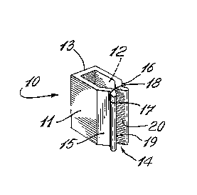
Fig. l is a perspective view of the identi-
fication clip of the present invention;
Fig. 2a is a perspective view of the garment
hanger and clip holder design for use with the clip of
Fig. l;
Fig. 2b is a fragmentary, enlarged, side
view of the garment hanger showing the identification
clip inserted in the clip holder;
Fig. 2c is an enlarged, fragmentary,
exploded, perspective view of the identification clip
and clip holder;
Fig. 3a is a sectional view, taken along
line 3-3 of Fig. 2b, and showing the identification
clip partially inserted on the clip holder; and
Fig. 3b is a sectional view, taken along
line 3-3 of Fig. 2b, showing the identification clip
fully inserted.
Referring now to Fig. 1, we have shown
generally at reference numeral 10, a perspective view
of an identification clip according to an embodiment of
the present invention. The identification clip 10 can
be made of molded plastic which is resilient enough to
prevent breakage when inserted in the clip holder, or
can similarly be made of metal.
Identification clip 10 is provided with
parallel side walls 11 and 12 with a bight 13 to form a
display area to enable the garment manufacturer or
store reseller to indicate the size or colour or other
identification of the garment placed on the hanger.

21~8171
_ - 4 -
Parallel side walls 11 and 12 form the clip
opening 14 at the other end. The clip opening 14 is
formed by the parallel side walls 11 and 12 having con-
verging wall portions 15 and 16 to meet at an apex 17
and 18 and then diverging wall portions 19 and 20. The
apexes 17 and 18 of parallel side walls 11 and 12 form
a retaining nip which, when used with the clip holder,
makes the removal of the identification clip difficult.
Referring now to Figs. 2a, 2b, and 2c, there
is shown a typical garment hanger, having a body 25 and
a hook 26. The garment hanger can be made of a one-
piece unitary molded plastic. The identification clip
holder shown generally at reference numeral 27 is com-
prised of a retaining pin 28 and a flange 29, both
disposed and fixedly connected between end pieces 30
and 31 which are formed between the body 25 and the
hook 26 of the garment hanger. A gap 24 is defined
between the pin 28 and flange 29. The identification
clip 10 is adapted to fit within close tolerances
between end members 30 and 31, as is shown in Fig. 2b.
In Fig. 2b, the identification clip 10 is
shown fully inserted on the clip holder 27. As will be
shown more clearly further below, the clip opening 14
is adapted to be located in the gap 24 adjacent flange
29 when the identification clip is fully inserted onto
clip holder 27. Thus, in this arrangement, the ends of
wall portions 19 and 20 of the identification clip 10
are directly adjacent end members 30 and 31 and abut
against the flange 29, closing the gap 24, whereas the
clip opening 14 is hidden within the gap 24. Thus,
this arrangement prevents the manual removal of the
identification clip from the garment hanger.
In Fig. 3a, the mating of the identification
clip 10 as it is inserted onto clip holder 27 is illus-
trated. Retaining pin 28 is provided with a pointed
nose 33 and sides 34a and 34b which are divergent to
facilitate the insertion of the identification clip 10

~ ~ 5 - 21~8171
on the clip holder 27. In particular, side wall por-
tions 19 and 20 of identification clip 10 are spread
open by divergent sides 34a and 34b as they are pushed
onto retaining pin 28. Retaining pin 28 is provided
with a first set of grooves 35a and 35b to temporarily
retain the identification clip 10 on the clip holder 27
until it is fully inserted onto the holder. If the
identification clip does not correspond to the garment
placed on the garment hanger, it can easily be removed
by simply pulling on the identification clip.
In Fig. 3b, the sectional view of the clip
holder 27 is shown with the identification clip 10
fully inserted in the holder. As can be seen, once
clip 10 is fully inserted, the tapered side walls 19
and 20 return to their rest position grasping the
retaining pin 28. In addition, the opening 14 of
identification clip 10 is confined within the gap 24
thereby making it difficult to manually remove the
identification clip 10. A small gap 36 remains between
flange 29 and the ends of side wall portions 19 and 20
of retaining clip 10 to enable the insertion of a tool
for removal of the identification clip 10. Once
inserted, the nose 33 of retaining pin 28 abuts the
inner side of the bight 13 of identification clip 10.
As can be seen in Fig. 3, the apexes 17 and 18 of side
walls 11 and 12 form a retaining nip adapted to fit in
the gap 24 created between retaining pin 28 and flange
29.

Representative Drawing
A single figure which represents the drawing illustrating the invention.
Administrative Status

2024-08-01:As part of the Next Generation Patents (NGP) transition, the Canadian Patents Database (CPD) now contains a more detailed Event History, which replicates the Event Log of our new back-office solution.

Please note that "Inactive:" events refers to events no longer in use in our new back-office solution.

For a clearer understanding of the status of the application/patent presented on this page, the site Disclaimer , as well as the definitions for Patent , Event History , Maintenance Fee  and Payment History  should be consulted.

Event History

Description Date
Time Limit for Reversal Expired 2008-04-28
Letter Sent 2007-04-30
Inactive: Late MF processed 2006-09-29
Letter Sent 2006-04-28
Grant by Issuance 2000-09-19
Inactive: Cover page published 2000-09-18
Pre-grant 2000-06-23
Inactive: Final fee received 2000-06-23
Notice of Allowance is Issued 2000-06-06
Letter Sent 2000-06-06
Notice of Allowance is Issued 2000-06-06
Inactive: Approved for allowance (AFA) 2000-05-17
Letter sent 2000-03-07
Advanced Examination Determined Compliant - paragraph 84(1)(a) of the Patent Rules 2000-03-07
Inactive: Advanced examination (SO) fee processed 2000-02-24
Amendment Received - Voluntary Amendment 2000-02-24
Inactive: Advanced examination (SO) 2000-02-24
Inactive: Application prosecuted on TS as of Log entry date 1998-01-21
Letter Sent 1998-01-21
Inactive: Status info is complete as of Log entry date 1998-01-21
Request for Examination Requirements Determined Compliant 1997-10-28
All Requirements for Examination Determined Compliant 1997-10-28
Deemed Abandoned - Failure to Respond to Maintenance Fee Notice 1997-04-28
Inactive: Adhoc Request Documented 1997-04-28
Application Published (Open to Public Inspection) 1996-10-28

Abandonment History

Abandonment Date Reason Reinstatement Date
1997-04-28

Maintenance Fee

The last payment was received on 2000-04-11

Note : If the full payment has not been received on or before the date indicated, a further fee may be required which may be one of the following

  • the reinstatement fee;
  • the late payment fee; or
  • additional fee to reverse deemed expiry.

Patent fees are adjusted on the 1st of January every year. The amounts above are the current amounts if received by December 31 of the current year.
Please refer to the CIPO Patent Fees web page to see all current fee amounts.

Fee History

Fee Type Anniversary Year Due Date Paid Date
Request for examination - standard 1997-10-28
MF (application, 3rd anniv.) - standard 03 1998-04-28 1998-04-08
MF (application, 4th anniv.) - standard 04 1999-04-28 1999-04-27
Advanced Examination 2000-02-24
MF (application, 5th anniv.) - standard 05 2000-04-28 2000-04-11
Final fee - standard 2000-06-23
MF (patent, 6th anniv.) - standard 2001-04-30 2001-01-11
MF (patent, 7th anniv.) - standard 2002-04-29 2002-03-25
MF (patent, 8th anniv.) - standard 2003-04-28 2003-03-31
MF (patent, 9th anniv.) - standard 2004-04-28 2004-04-19
MF (patent, 10th anniv.) - standard 2005-04-28 2005-04-22
2005-04-22
MF (patent, 11th anniv.) - standard 2006-04-28 2006-09-29
Reversal of deemed expiry 2006-04-28 2006-09-29
Owners on Record

Note: Records showing the ownership history in alphabetical order.

Current Owners on Record
E.R.A. DISPLAY CO. LTD.
Past Owners on Record
MARC TREMBLAY
STANLEY EILEY
Past Owners that do not appear in the "Owners on Record" listing will appear in other documentation within the application.
Documents

To view selected files, please enter reCAPTCHA code :


To view images, click a link in the Document Description column (Temporarily unavailable). To download the documents, select one or more checkboxes in the first column and then click the "Download Selected in PDF format (Zip Archive)" or the "Download Selected as Single PDF" button.

List of published and non-published patent-specific documents on the CPD .

If you have any difficulty accessing content, you can call the Client Service Centre at 1-866-997-1936 or send them an e-mail at CIPO Client Service Centre.

({010=All Documents, 020=As Filed, 030=As Open to Public Inspection, 040=At Issuance, 050=Examination, 060=Incoming Correspondence, 070=Miscellaneous, 080=Outgoing Correspondence, 090=Payment})


Document
Description 
Date
(yyyy-mm-dd) 
Number of pages   Size of Image (KB) 
Description 1996-10-27 5 228
Claims 1996-10-27 2 59
Abstract 1996-10-27 1 13
Drawings 1996-10-27 3 84
Representative drawing 1997-12-15 1 19
Claims 2000-02-23 3 127
Representative drawing 2000-09-04 1 7
Acknowledgement of Request for Examination 1998-01-20 1 178
Commissioner's Notice - Application Found Allowable 2000-06-05 1 162
Maintenance Fee Notice 2006-06-26 1 172
Late Payment Acknowledgement 2006-10-16 1 166
Maintenance Fee Notice 2007-06-10 1 173
Correspondence 2000-06-22 1 48
Fees 2005-04-21 1 22
Fees 2006-09-28 1 26
Fees 1997-04-09 1 54
Courtesy - Office Letter 1995-11-07 1 10
Prosecution correspondence 2000-02-23 2 76