Note: Descriptions are shown in the official language in which they were submitted.
G'~, .
~ 4~197
74977-2
WIRELINE SET, TUBING RETRIEVABLE WELL PACKER
WITH FLOW CONTROL DEVICE AT THE TOP
Technical Field
The invention generally relates to retrievable well
packers which may be set by wireline and retrieved by tubing
string.
'.'~.','.""'~'" .
Backqround of the Invention
Well packers utilized for isolating a zone in a well ;
below the packer from a zone above the packer for performing a - ~ -
well service operation such as acidizing, perforating, formation
fracturing or pressure cont~;nm~nt are known. Further, it is
known to initially run a packer downhole to a selected position
and to set the packer using wireline apparatus. After setting,
the wireline is removed from the well and a tubing string is run
down the well and attached to such packers for performing the
well servicing operation. The packer can then be removed from ~;
::: ~.: :.
the well by manipulation of the tubing string and pulling of the
tubing string and packer. The packer can then be redressed and
used again in the same well or at another location.
Flow through the packer must be prevented for a time
in order to connect the tubing string and often to perform the
service operation. In such situations, the packer is ~-
essentially used as a temporary bridge plug. Typically, in
prior art devices, in order to seal off flow through the packer, ~
a pump-out plug or flow control device is installed below the ~ -'
~ ,:.' '
.:
2~48197
74977-2
packer. A pump-out plug is subsequently removed by applying
pressure through the tubing string to release the plug from the
packer with the result that the pump-out plug is left behind as
debris below the packer when the packer is removed. Other prior
art devices utilize a flow control device, such as a blanking
plug, installed in an accommodating profile at the bottom of the
packer and later removed by wireline to allow flow through the
packer. However, during service operations or connection of the
tubing string, debris can accumulate in the bore of the packer
above the blanking plug impairing its retrievability.
Accordingly, it is desirable that the flow control device be
located at the top of the packer. In known prior art tools, the
:
flow control device is moved to the top of the packer by
wireline after the packer is set and the tubing string is
attached which requires an additional trip on wireline through
the tubing string.
In one specific currently available retrievable
packer, a tubular mandrel is connected to a wireline setting
~ device through a wireline adaptor. A pair of slip assemblies
;
and a sealing unit are mounted on the mandrel of the packer to
allow the packer to be set in the well casing and to create a
. .
seal in the casing isolating a well zone below the packer from a
well zone above it. A slick joint is mounted on the top of the
mandrel having a plug receiving annular groove. The adaptor
~.~
includes an elongated rod which is telescoped through the slick
joint and a connecting means frangibly secures the bottom the
rod in the joint recess where the slick joint and mandrel are
~, ,,, ~, . ~ ~; : ' '' '
,; ,.,,, "
~,~,. -.. ; . -., ,~.'. : ~ ,- ~ ~ ' '~ i
~'': ~
~ :
2 1 ~ ~ 1 9 7
74977-2
threaded. The top of the rod is connected directly to a i~
wireline setting device. A long sleeve attached to the housing ;
of the wireline setting device rests on the top of the packer.
A simultaneous application of force from the housing of the
wireline setting device, through the sleeve, to the top of the
packer in the downward direction and an upward pulling force on
the connecting means provides relative motion between the slip
assemblies and sealing unit, and the mandrel required to set the
packer. However, since the rod extends through the slick ~oint -
past the plug receiving annular groove, it is not possible to
seat a flow control device at the top of the mandrel.
A similar type of tool is disclosed in Canadian patent - ;~
1,286,602. The adaptor disclosed in that patent utilized for
setting the packer includes a rod which is telescoped through ;
the tool and frangibly secured to the bottom of the mandrel. In
this tool, as in the previous one, the pump-out plug or flow -~ 6
control device must be located beneath the packer because the
rod runs through the plug accommodating profile.
.
Summary of the Invention
The present invention attempts to overcome the above-
.
noted problems by providing an improved adaptor for use in
running and setting a packer on wireline. Specifically, the
present invention provides an adaptor, a wireline well packer
setting assembly and a method for running and setting a well
packer in a well by wireline with a flow control device seated
at the top of the packer. More specifically, the present ~-
.''~ .... ,~
' 214~197
74977-2
invention provides a unique adaptor enabling a flow control :
device to be seated at the top of the packer during installation
on wireline and setting by a wireline setting device.
Thereafter, with the wireline setting device and adaptor removed
from the packer, production tubing or the like may be connected
to the packer downhole, the flow control device may be removed
from the packer by wireline through the tubing, and the packer
may be subsequently released and retrieved from the well by
manipulation and pulling of the tubing from the well.
10Accordingly, the present invention provides an adaptor
for use in setting a well packer by means of a wireline setting
device with a flow control device removably seated at the top of
said well packer and wherein said well packer is of the type
including outer packer housings including slip assemblies and a
sealing unit, and a tubular mandrel extending there through for
relative movement therebetween to anchor said packer to the well
casing and to create a seal in said casing, wherein said adapter
comprises: (a) a first member engaged with said wireline
: setting device and an upper packer housing for applying a force
in a first direction on said upper packer housing when said
wireline setting device is actuated; and (b) a second member
engaged with said wireline setting device and said mandrel for
applying a force in a second direction opposite to said first
direction, when said wireline setting device is actuated; and
wherein (c) after said packer is engaged with said well casing
~: and actuated to create said seal continued application of force
by said wireline setting device causes said adaptor to disengage
: 4
2 ~ 4 8 1 9 7
74977-2
from said packer such that said adapter may be completely
removed from said packer with said flow control device rem~n;ng
seated at the top of said packer to inhibit flow through said
tubular mandrel. :
The present invention further provides a wireline well
packer setting assembly for use in setting a well packer of the
type including outer packer housings including slip assemblies .-
and a sealing unit, and a tubular mandrel extending therethrough
. . .
for relative movement therebetween to anchor said packer to the
well casing and to create a seal in said casing comprising: (a)
a wireline setting device; (b) an adaptor having: (i) a first
member engaged with said wireline setting device and an upper
packer housing for applying a force in a first direction on said
upper packer housing when said wireline setting device is
actuated; (ii) a second member engaged with said wireline
setting device and said mandrel for applying a force in a second
direction opposite to said first direction when said wireline
setting device is actuated; (c) a flow control device seated at - .
the top of said well packer; and (d) wherein upon actuation of :.
said wireline setting device, said well packer is engaged with :
said well casing and actuated to create said seal by relative ~.
movement between said packer housings and said mandrel and : :
wherein continued application of force by said wireline setting
device on said first and second members of said adaptor causes
said adaptor to disengage from said packer such that said
adaptor is completely removed from said packer with said flow
~ :
~148197
74977-2
control device remaining seated at the top of said packer to
inhibit flow through said tubular mandrel.
The present invention further provides a method for
setting a well packer having a tubular mandrel in the casing of
a well by wireline and retrieving said packer by tubing string
comprising: (a) removably seating a flow control device adapted
to inhibit fluid flow inside the top end of said tubular
mandrel; (b) connecting a wireline setting device to the end of
a wireline; (c) releasably connecting said well packer to said
wireline setting device; (d) running said well packer down said ~:
well to a selected position on said wireline; (e) actuating said
wireline setting device to set said packer and to thereafter
release said packer from said wireline setting device with said
flow control device rem~;n;ng seated at the top end of said
packer; (f) connecting a tubing string to said packer;
(g) engaging said flow control device by a wireline tool run
.
through said tubing string, for removal and retrieval of said
~ flow control device to allow l~ninh;hited fluid flow through said
5~ tubular mandrel; and (h) retrieving said packer when it is no
longer required downhole by manipulating said tubing string to
disengage said packer and pulling the tubing string and packer .
to surface.
~ .
Brief Description of the Drawinqs
The invention will be further described, by way of
example, with reference to the following drawings wherein:
' '1481~7
74977-2
Figures l(a) - l(c) are schematic illustrations of the
operating principles of one embodiment of the invention, showing
a packer being lowered into the well, being set and being ~
retrieved from the well respectively; :~:
Figures 2(a) - 2(d) are a cross-sectional and
elevational view of a wireline well packer setting assembly and '
: well packer shown as positioned as they would be when run into
: the well;
,
~ Figures 3(a) - 3(d) are a cross-sectional and ~
-,: ~
elevational view of the wireline well packer setting assembly
and well packer with the packer shown installed in the well; ; '
Figures 4(a) - 4(d) are a cross-sectional and
.,., ,.~ ,
elevational view of the packer attached to a tubing string, the ~ ~
packer being positioned as it would be when it is being ~ ;
retrieved from the well; :~
;~ ~ Figure 5 is a schematic illustration of the slip
elements and related components of the packer.
Detailed Description
:20 Referring to Figure 1 which illustrates one embodiment
of the present invention, a pac-ker generally designated 1 is
; initially attached to an adaptor generally designated 2 which is :; ;~. .:.
in turn attached to a wireline setting device generally -
-~ ~ designated 3. Figure l(a) shows the packer 1, adaptor 2 and
wireline setting device 3 as they would be when they are being :~
run into the well on wireline ~not shown). Figure l(b) shows
the packer 1, adaptor 2, and wireline setting device 3 as they :~
, ~ : ,,
~: 7
~; ,: ,''
. . " . ~ . ~ ,
:
-~ ~14~197
74977-2
would be during setting of the packer. Figure l(c) shows the
packer 1 attached to an on/off tool generally designated 4 which
is in turn connected to a tubing string (not shown) with the
packer shown disengaged from the well casing for retrieval from
the well.
Generally, the packer 1 is run down the well on the
wireline adaptor 2 which is in turn connected to the wireline
setting device 3 such that, upon actuation of the wireline
setting device 3, the packer 1 is anchored and actuated at a
selected downhole position as a means of isolating the zone of
the well below the packer from the zone above it. In Figures
l(a) and l(b),a flow control device 10 is shown removably seated
in a plug accommodating profile in a mandrel 12 of the packer 1.
In Figure l(c), the flow control device 10 has been removed from
~ ~ the mandrel 12 of the packer 1.
;:~ The packer 1 includes the mandrel 12 and a number of
outer packer housings including upper and lower slip assemblies
14, 16 and sealing unit 18.
The upper and lower slip assemblies 14, 16 each
; 20 include slip elements 20 (see Figure 5) adapted to bite into the
, ~
inside surface of the well casing 22 when engaged. The slip
elements 20 on the upper slip assembly 14 are oriented such that
the slip elements 20 bite into the inside surface of the well
casing 22 to anchor the packer 1 against being pulled upwardly
within the well. Similarly, the lower slip assembly 16 is
oriented such that the slip elements 20 anchor the packer 1 .
against being pushed downwardly within the well.
.
i i
1 9 7
74977-2
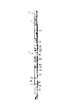
Referring to Figure 2(b), the upper slip assembly 14
is frangibly secured by means of shear screws 26 to the
mandrel 12. A take up spring 28 is likewise frangibly secured
to the mandrel 12 by the shear screws 26. Slip springs 30 are
provided to urge the slip elements 20 of the upper slip assembly ;~
14 into a retracted position in which they are held away from
engagement with the casing 22. The take up spring 28 generally
urges the upper ~lip assembly 14 downward but the slip assembly
14 is initially prevented from moving on the mandrel 12 by the
shear screws 26. ~;~
The lower slip assembly 16 also includes slip elements
20, and those slip elements 20 are urged into retracted position
away from engagement with the well casing 22 by means of slip
springs 32. Connected to the lower slip assembly 16 is a jay ;~
housing 34 within which is formed a set of jay slots 36 each ~-;
having a lower trap 37 and an upper trap 39. The lower slip -~
assembly 16 and jay housing 34 are frangibly secured to the - ~
mandrel by means of shear screws 38. ~;;
The sealing unit 18 is located on the mandrel 12
between the upper and lower slip assemblies 14, 16. The sealing
~; unit 18 includes elastomeric seals 40 which are adapted to be ~
.~ , .
pressed against the inside surface of the casing 22 to seal the
~,~ annular area between the packer 1 and the casing 22 when the
packer 1 is actuated. The sealing unit 18 is connected to an
1'~ ,
upper cone 42 and a lower cone 44 which are free to move
relative to the sealing unit 18. The cones 42, 44 are
configured to engage the slip elements 20 to force the teeth 24
:
214~197
74977-2
outwardly to engage the well casing 22 upon actuation of the
packer 1.
A set of jay pins 46 are connected to the mandrel 12
by way of connecting means 48. The jay pins 46 and hence the
mandrel 12 are free to ride wlthin the jay slots 36 formed in
the jay housing 34.
; At the upper end of the packer, coupling pins 50
extend radially outward and are adapted to nest within a trap 52
of a connecting recess 54 in an on/off tool 4 attached to a
tubing string 56 (see Figure 4(a)).
The mandrel 12 of the packer 1 includes a flow control
device receiving annular groove 58 at the top portion of the
packer mandrel 12. A flow control device such as a blanking
~: plug 60 is seated in the plug receiving annular groove 58. The
blanking plug 60 includes a prong 62 which extends upwardly
:~ ~ above the top of the mandrel 12 when the blanking plug 60 is :
seated in the flow control device annular groove 58.
~: The blanking plug 60 is seated in the flow control
device i~nn~ r groove 58 during running of the packer 1 into the
20 . well and setting of the packer 1 by the wireline setting
device 3.
.
~;: The illustrated wireline setting device 3 is a device
of the type well known in the art which is operated by means of
an explosive charge (not shown). However, any known wireline
;~ setting device may be utilized within the ambit of the invention
so long as it includes means for appiication of force in two
different directions.
~;
,r~ .
2148197
74977-2
In the illustrated wireline setting assembly, the
wireline setting device 3 includes a housing 64 and a
plunger 66. An outer sleeve 68 of the adaptor 2 is connected to ~3
the housing 64 of the wireline setting device 3 and has a lower
end resting on cap 70 of the upper slip assembly 14. A rod 72
of the adaptor 2 is connected to the plunger 64 of the wireline
setting device 3 by means of rod adaptor 74. The rod 72 is in
turn frangibly secured to the packer mandrel 12 by means of a
shear collar 76 and a collet 78 including collet fingers 79.
Specifically, the rod 72 includes a rod cone 80 located at the ;~
lower end of the rod 72 which forces the end of collet fingers ~: -
79 into engagement with recess 82 inside the top of the packer
mandrel 12. The recess 82 is located above flow control device : ~
annular groove 58. :- ~ ,
~.
The shear collar 76 and rod 72 are telescoped through
the collet 78 with the shear collar 76 initially firmly secured
to the rod 72. As may be noted from Figure 2(a), the rod cone
~: 80 initially extends downwardly over the prong 62 and upper ~
~: portion of the blanking plug 60. ::
?~ 20 In transport configuration of the packer (see Figures
: : .
2(a) - 2(d)), the mandrel 12 is disposed in a lower position 1:
~ relative to the jay housing 34, with the jay pins 46 captured '~
.i: within the lower trap 37 of the jay slots 36 (see Figure 2(d)).
The upper slip assembly 14 and lower slip assembly 16 are held :~ -
just touching the upper cone 42 and lower cone 44 respectively . ~.
by the shear screws 26, 38. In this position, the packer 1
,.~
attached to the adaptor 2 which is in turn attached to the
3 ,~
2148197
74977-2
wireline setting device 3 are run down the well to a selected
position. .--
Once located at the selected position, the wireline
setting device 3 is actuated from surface by suitable means such
as an electric charge sent down the wireline (not shown) causing
a simultaneous application of force by the housing 28 through
the sleeve 68 of the adaptor 2 to the cap 70 of the upper slip
assembly 14 in a downward direction, and from the plunger 66
through the rod 32, shear collar 35 and collet fingers 79 to the
mandrel 12 in an upward direction.
The upward force on the mandrel 12 pulls it upwardly
causing the jay pin 46 connected to the mandrel 12 to pull
upwardly on the jay housing 34 and lower slip assembly 16,
breaking the shear screws 38. The slip elements 20 of the lower
slip assembly 16 are then pushed onto the lower cone 44 forcing
them from the retracted positions into their anchoring position
wherein the teeth 24 bite into the well casing 22 and anchor the
packer 1 from moving downwardly within the well. Similarly, the
downward motion of the housing 64 shears the shear screws 26 and
pushes the upper slip assembly 14 onto the upper cone 42 forcing
the slip elements 20 of the upper slip assembly 14 into the
casing 22. The take-up spring 28, being in a generally
compressed condition, also urges the slip elements 20 of the
upper slip assembly 14 onto the cone 42 ensuring that they
engage the well casing 22 to anchor the packer 1 from moving
upwardly within the well (see Figure 3(b)). At the same time
the sealing unit 18 is deformed such that the elastomeric
12
,
214~197
74977-2
elements 40 seal against the inside surface of the well casing
22 (see Figure 3(c)). -
Once the packer 1 is set in the well casing 22 with
the sealing unit 18 deformed, continued setting force from the ~ - ~
wireline setting device 3 shears the shear collar 76. As the :~ .
wireline setting device 3 continues to stroke, the collet
fingers 79 remain engaged in the recess 82 of the packer mandrel ~: -
12 while the rod 72 moves upward. Accordingly, the rod cone 80
is pulled from engagement with the collet fingers 79 and allows ;~
the collet fingers 79 to collapse and disengage from the mandrel
12. As seen in Figure 3(a), the lower portion of the broken
shear collar 76 and the collet 78 rest on the upper portion of :~
the rod cone 80 so that they are retrieved along with the :
wireline setting device 3. Further, the wireline setting device :~
3 and adaptor 2 are completely released and removable from the
packer 1 and may be retrieved from the well on the wireline (not ~ :~
shown) leaving the packer 1 behind with the blanking plug 60 -~
seated in the flow control device annular groove 58 in the
mandrel 12. This exposes the upper end of the packer and its
coupling pins 50 for connection to the on/off tool 4 which i9
connected to the tubing string 56 (see Figure 4(a)). :
When it is desired to attach the packer 1 to the
tubing string 56, the tubing string 56 with the on/off tool 4
connected to the end thereof is lowered onto the packer and the
tubing string 56 is manipulated to latch the on/off tool to the
.
:~ coupling pins 50 of the packer.
After the tubing string 56 is attached to the packer 1 . :
:: :
:~ 13 ~
"
" 21~8197
74977-2
flow through the packer mandrel 12 and tubing string 56 may be
reestablished by removal of the blanking plug 60 through .
standard wireline techniques.
When it is desired to retrieve the packer 1 from the
well the slip assemblies 14, 16 must be released from their set
position. In order to release the slip assemblies 14, 16 from
their set position, the tubing string 56 and mandrel 12 are
lowered slightly while applying torque to the tubing string 56.
This shifts the jay pin 46 out of the lower trap 37 so that an
upward pull on the tubing string 56 while maintaining the torque
thereon causes the mandrel 12 to travel upwardly with the jay
pin 46 riding within the jay slot 36 into the upper trap 39
(Figure 4(d)). As the mandrel 12 is lifted, a shoulder 84 near
the top of the mandrel lifts the upper slip assembly 14 off the
upper cone 42 and slip springs 30 retract the slip elements 20
and release the force applied to the sealing unit 18 which
returns to its undeformed condition (Figure 4(b)). As the
mandrel 12 continues moving upwards, a shoulder 86 on the lower
~: portion of the mandrel 12 engages the bottom of the sealing unit
18, moving it upward which in turn lifts the lower cone 44 out
~ from engagement with the lower slip elements 20 of the lower
: slip assembly 16 and slip springs 32 retract the lower slip
elements 20 disengaging them from the well casing 22 (Figure
4(c)). The tubing string 56 and the packer 1 may then be
.
~: retrieved from the wall.
-
- ~
: . .
:. : -:.
- 14 .~
.:~. . :.- .:
., .~,,.,~ ,,,
~148197 ~
74977-2 ~'
Those skilled in the art will recognize that the ~ :~
aforesaid description is by way of example only. Modifications
may be made within the scope of the invention as set out in the
appended claims.
. :.
~: ',. :.
:
: . . .~:~
~, . ; ,
.
.
- ~ ~
}.,~ j , i ~', ::,
~ ~ .
"'' ~ ' :
. ~ ~
~ 15
:: '
.,.; . . . .