Note: Descriptions are shown in the official language in which they were submitted.
TE,~ TR~S~ S ~. ~r~ 21 ~ 8 2 7 9
Wire-free telecommunications system, preferably a
cordless telecommunications system
The invention relates to a wire-free telecommunications
system, preferably a cordless telecommunications system
according to the preamble of patent claim 1.
In wire-free telecommunications systems - such as mobile
radio or cordless telecommunications systems for example
- having a plurality of base stations and mobile elements
which form telecommunications subsystems and use, for
example, the time division multiple access method TDMA
(Time Division Multiple Access) or the code division
multiple access method CDMA (Code Division Multiple
Access), optimum channel utilization in the telecommuni-
cations subsystems (in the sense of no mutual interfer-
ence between the channels in the telecommunicationssubsystems) can be achieved only if the telecommunica-
tions subsystems, which are based, for example, on the
TDMA principle, are synchronized (no drift between the
time bases of the telecommunications subsystems) (syn-
chronous wire-free telecommunications system).
In asynchronous wire-free telecommunications systems, in
contrast, in which drift occurs between the time bases of
the telecommunications subsystems, mutual interference
between the channels of the telecommunications subsystems
can occur as a result of the drift of the time bases,
which interference severely reduces the overall channel
selection which can be used in the respective telecom-
munications subsystem in unfavorable cases.
The object on which the invention is based is to specify
a wire-free telecomrln;cAtions system, preferably a
cordless telecommunications system of the type mentioned
initially, in the case of which there is no mutual
interference between telecommunications subsystems.
- 2 - ~ ~ ~ 8 279
This object is achieved, based on the wire-free
telecommunications system defined in the preamble of patent
claim 1, by the features specified in the characterizing part
of patent claim 1.
It can be regarded as being essential to the invention
in this case that only a subset of the time slots which are
available overall in the telecommunications subsystems of the
wire-free telecommunications system (for example, every other
time slot) is used. In consequence, the usable channel capacity
of the wire-free telecommunications subsystem or telecommunica-
tions system is admittedly reduced, but the reduced channel
capacity is preferably not less if, to be precise, all the time
slots which are available in the telecommunications subsystems
are used, but only half of these are available, rather than all
of them, because of interference in which a channel a of a
telecommunications subsystem A interferes with two channels bl,
b2 of a telecommunications subsystem B.
In accordance with the present invention, there is
provided a wire-free telecommunications system having a
plurality of base stations and mobile elements which form a
wire-free telecommunications subsystem, the wire-free tele-
communications system comprising: each of the base stations
and each of the mobile elements having a circuit arrangement
to which is assigned a controlling program; the controlling
program forming radio links at predetermined frequencies and
in a plurality of time slots in time-division multiplex
channels, the controlling program selecting for forming the
A 20365-3449
- 2a -
radio links only a subset of time slots which do not follow
one another directly, from a number of time slots of the
plurality of time slots, said number of time slots being
predetermined for the radio links within one time division
multiplex frame.
Advantageous developments of the invention are
specified in the subclaims.
An exemplary embodiment of the invention is described
with reference to the drawings, in which:
Figure 1 shows the outline of the construction of a
base station or of a mobile element of a cordless tele-
communications subsystem,
Figure 2 shows a TDMA time frame of a cordless tele-
communications subsystem using the DECT Standard,
Figure 3 shows a diagram for in each case two
synchronous and asynchronous wire-free telecommunications
subsystems based on the TDMA principle, and the level of
interference resulting from the channels of the wire-free
telecommunications subsystems.
20365-3449
A
21~8279
- 3 -
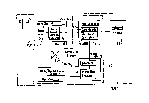
Figure 1 shows the outline of the circuit construction of
a base station FT or of a mobile element PT of a cordless
telecommunications system. Both the base station FT and
the mobile element PT contain a radio element RE - also
referred to as the transceiver device RE-T, RE-R in the
following text -, a controlling element CE and peripheral
circuit elements (peripheral elements) PE, which are
combined in the "peripheral elements" functional block.
The following description assumes that the DECT StAn~rd
(Digital European Cordless Telecommunication) is imple-
mented for the cordless telecommunications subsystem.
Rowever, the invention is not limited to this. The
invention can thus also be used directly on comparable
stAn~Ards, such as the CT2 or GSM StAn~rd, for example.
While the base station FT and the mobile element PT do
not differ with respect to the controlling element CE and
the radio element RE or the transceiver device RE-T, RE-R
- to the extent of the consideration relevant to the
invention -, the peripheral circuit elements PE of the
base station FT and of the mobile element PT are con-
structed differently.
Thus, the peripheral circuit elements PE in the base
station FT - based on base stations of known cordless
telephone systems (Wolf, Klaus: "Auch ohne Schnur "auf
Draht"" [Without any cord ~by wire"], Telcom Report 10,
1987, Issue 2, pages 130 et seq., for example page 134) -
comprise, for example,-internal subscriber circuits and
exchange or private branch exchange circuits having
upstream ADPCM encoding/decoding devices and an internal
peripheral controller, while in [sic] the peripheral
circuit elements PE of the mobile element PT - based on
mobile elements of known cordless telephone systems
(Telcom Report 10, 1987, Issue 2, page 135) - contain,
for example, a microphone, a piezo receiver capsule, a
piezo tone caller, an accumulator, a keyboard, an LED
display and NF and tone caller amplifiers.
- 21482~9
-- 4 --
The peripheral circuit elements PE stated above in the
base station FT and in the mobile element PT can also be
replaced by other circuit elements, without any limita-
tion of the invention.
Those elements of the circuit construction of the base
station FT and of the mobile element PT according to
Figure 1 which are relevant to the invention are the
radio element RE, or the transceiver device RE-T, RE-R,
and the controlling element CE. Two antennas A1, A2,
which operate both as transmitting and receiving anten-
nas, are in this case assigned to the radio element RE
for transmitting and receiving radio signals (for example
TDMA or CDMA radio signals). Alternatively, it is also
possible, however, without any limitation of the inven-
tion, to assign one antenna or more than two ante~nAS tothe radio element RE.
Furthermore - as is illustrated by three functional
blocks in Figure 1 - the radio element RE has a trans-
ceiver element T,R, a field strength measuring device
(Radio Signal Strength Indicator) RSSI and an interface
device RE-I, which are connected to one another in the
radio element RE in the manner illustrated. The field
strength measuring device RSSI measures the field
strength of the radio signals selected via the antennas
A1, A2 and in the transceiver element T, R.
The field strength measuring device RSSI is generally
used for testing whether a channel is busy (cf. DECT
Draft prETS 300 175-3: 1991, page 164). The instruction
on how the field strength can be measured is specified in
the DECT Standard (cf. DECT Draft prETS 300 175-2: 1991,
page 31, 6.2 and page 38, 8.3). The occupancy of the
channel is in this case confirmed by measuring the field
strength (minimum field strength) of received radio sig-
nals, the measurement results RSSI1, ... subsequently
being fed via an analog/digital converter A/D to a thres-
hold value generator THVG (THreshold Value Generator)
2148279
-- 5 --
which is integrated in a main processor M-CT of the
controlling element CE. The threshold value generator
THVG in this case continuously forms updated values
during continuous operation of the base station FT or of
the mobile element PT, which values are linked by the
main processor M-CT to a controlling program CP and are
used for selecting the antennas A1, A2. The controlling
program CP uses the information obtained from the thresh-
old value generator THVG on the channel occupancy (input
variable) to form controlling data CDATA, which are fed
via a main processor interface M-CTI to a subprocessor
(subcontroller) S-CT.
The subprocessor S-CT is designated as the Time Switch
Controller in the base station FT and as the Burst Mode
Controller in the mobile element PT. Assigned to the sub-
processor S-CT, inter alia, is a multiplexer/demulti-
plexer unit MUL/DEM, which respectively produces and
receives 1.152 Mbit/s data using the DECT burst format.
Furthermore, the subprocessor S-CT carries out control-
ling tasks for the radio element RE and the peripheralcircuit elements PE. In the case of the base station FT,
the multiplexer/demultiplexer unit MUL/DEM of the
subprocessor S-CT assigns to the received data packets
and-to the data packets to be transmitted, respectively,
for example up to six internal and three external
telephone connections, respectively, using the time
division multiple access method TDMA (Time Division
Multiple Access) or using the code division multiple
access method CDMA (Code Division _ultiple Access).
Furthermore, the subprocessor S-CT contains a
timer/counter TI/CO which clocks the subprocessor S-CT,
preferably with respect to the occurrence in time of
bits, time slots and TDMA or CDMA frames.
The method of operation of cordless telecommunication in
a cordless telecommunications system having the base sta-
tion FT and the mobile element PT according to Figure 1
is indicated in principle by the documents already
21~$279
- 6 -
mentioned (Telcom Report 10, 1987, Issue 2, pages 130 et
seq., and DECT Draft prETS 175-3: 1991, entire document).
Thus, a plurality of frequencies (FDMA = Frequency
Division _ultiple _ccess) and, subsequently to this, a
plurality of time slots of time-division multiplex chan-
nels (TDMA = Time Division Multiple Access) are assigned
in the cordless telecommunications subsystem to bidirec-
tional (transmitter/receiver and receiver/transmitter)
radio links. In so doing, in the case of the bidirec-
tional radio link in the cordless telecommunications sub-
system between the base station FT and the mobile element
PT speech is, on the one hand, compressed and transmitted
at the tran~mitting end and, on the other hand, it is re-
ceived and e~pAn~e~ at the receiving end.
In order to keep low the mutual interference from chan-
nels of the cordless telecommunications subsystems in a
wire-free telecommunications system, the controlling
program CP which is assigned to the main processor M-CT
of the controlling element CE in the base station FT or
the mobile element TT according to Figure 1 is designed
in such a manner that, using the controlling data CDATA
which is fed to the subprocessor S-CT, only a subset of
time slots which do not follow one another directly (for
example only every other time slot 0, 2, 4, ... 10, 12,
14, .... 22; or 0, 3, 6, 9, 12, 15, 18, 21) is selected,
from a number of predetermined time slots (Figure 2), for
the radio links.
Figure 2 shows a DECT-specific TDMA time frame for cord-
less telephone systems according to the DECT StAn~Ard. A
dynamic channel selection from approximately 120 avail-
able channels is carried out, according to the DECT
StAn~Ard, for cordless communication. The 120 channels
result from the fact that ten frequency bands between 1.8
and 1.9 GHz are used in the DECT StAn~Ard, a time-divi-
sion multiplex frame of 10 ms being used in time-division
multiplex (TDMA = Time Division Multiple Access) in each
frequency band according to the illustration in Figure 3.
21~2~9
24 (from O to 23) time channels are defined in this time-
division multiplex frame, and a frame scheme is thus
specified. This frame scheme iB then used in such a
manner that, for each frequency band, for example
12 mobile elements PT can be operated simultaneously in
duplex mode (PT-FT and FT-PT or FT-PT and PT-FT) with one
base station FT of a DECT communications system. In this
case, one time slot of 417 ~S in each case is assigned to
the 24 time channels. In this case, this time slot
indicates the time in which information (data) is trans-
mitted. This transmission of information in the duplex
mode is also called the ping-pong method because trans-
mission is carried out at a specific time, and reception
is carried out at a different time. In the case of this
ping-pong method, one time frame or pulse (burst) of
365 ~S, which corresponds approximately to a frame length
of 420 bits, is transmitted in each time slot, with a
data rate of 42 kbit/s. Taking into account the fact that
30 bits are in each case available, in order to avoid
adjacent time slots overlapping, at both ends of the time
frame in a guard space (GS) this results in an overall
data rate of 1.152 Mbit/s related to the time-division
multiplex frame.
Figure 3 shows mutual interference STB between two syn-
chronous wire-free telecommunications subsystems S-TKTSl,
S-TKTS2 (Figure 3a, Figure 3b) and asynchronous wire-free
telecommunications subsystems AS-TKTSl, AS-TKTS2
(Figure 3c, Figure 3d) of a wire-free telecommunications
system TKS with respect to time slots ZS and channels K
of the telecommunications subsystems.
The wire-free telecommunications system TKS is synchron-
ous when a firmly specified and constant phase (no drift)
exists between the time bases ZBl, ZB2 of the telecom-
munications subsystems S-TKTSl, S-TKTS2. In contrast to
this, the wire-free telecommunications system TKS is
asynchronous when a variable phase (drift of the time
bases ZB1, ZB2) exists between the time bases ZBl, ZB2 of
214827~
the telecommunications subsystems AS-TRTSl, AS-TRTS2.
The level of interference STB in the synchronous telecom-
munications subsystems S-TKTS1, S-TRTS2 according to
Figure 3a is 0% because of the antiphase synchronicity,
while it is 100% in the case of the synchronous telecom-
munications subsystems S-TRTSl, S-TRTS2 according to
Figure 3b, because of the in-phase synchronicity.
The level of interference STB in the case of the asyn-
chronous telecommunications subsystem AS-TRTSl, AS-TRTS2
according to Figure 3c is between 100% (maximum value)
and slightly above 50% (minimum value) depending on the
magnitude of the drift of the time bases ZBl, ZB2 in the
telecommunications subsystems AS-TRTSl, AS-TRTS2.
The level of interference STB in the case of the asyn-
chronous telecommunications subsystems AS-TRTS1, AS-TRTS2
according to the invention and according to Figure 3d is
a statistical mean of 50% if, in contrast to the asyn-
chronous telecommunications system TRS according to
Figure 3c, only every other time slot ZS, for example, is
selected. This is equivalent to a further time slot being
arranged between the two selected time slots ZS, which
further time slot is not used for radio links.