Note: Descriptions are shown in the official language in which they were submitted.
2198~03
ENCAPSULATED SHELF AND PROCESS FOR MAKING
BACKGROUND OF INVENTION
This invention relates to shelving and is particularly beneficial when used as
refrigerator shelving and the like.
Articles cont~ining liquid are spillable and, as is their nature, do spill. In the
context of a refrigerator for example, such a spill will typically soak into other items
and co"l~"~ le other foods. Extensive cleanup efforts will commonly be required
for spills which often flow dowllw~ld from one shelf to another shelf. Cont~inment
measures for limiting the area of such a spill are, therefore, desirable. One such
measure is a spill resistant shelf to contain a spill to the shelf upon which the spill
occurs to l~ i7.f', if not preclude, dowllward flow of the spill.
Previously known spill resistant shelves include a shelf with a two-piece
"picture frame" rim circumscribing the periphery of a glass panel or the like. Asilicone seal or the like is commonly provided between the frame and the top of the
glass panel for liquid spill resistance. However, such prior known spill resistant
shelves do not resolve and may actually promote yet another problem. Items whichare spilled upon such shelves can seep between the glass panel and the ~ulloullding
frame to a location which is difficult, if not practically impossible, to clean. Thus,
and in spite of the sanitary benefits of using a glass panel, for example, an lln~
condition readily develops when food stuffs become trapped between the panel andframe members of the known shelf structures.
Another consideration in designing shelving for a refrigerated colllpalllllent is
the circulation or convection of air through the colllpalllllent. Air circulation is
desirable to m~int~in a homogenous telllpeldlule distribution and avoid thermal
str~tifi~.~tion in which a range of temperature zones develop in the compartment with
the coldest zone at the bottom and the warmest zone at the top. Thus, the structure of
an effective refrigerator design will typically.include air passage spaces at either side
of and behind each solid shelf panel. However, the air passage spaces directly
decrease the shelf surface area. The width of a framing structure ~ull~ullding the
shelf as discussed above, also reduces the available shelf area. A reduction in shelf
area directly reduces the storage or holding capacity of the shelf and the associated
refrigerator. While the reduction in shelf area attributable to air passage around the
21i8903
shelf perimeter is dictated by thermodynamic performance, the area lost to perimeter
framing results from structural and design limitations imposed by accommodating the
convenience of a spill resistant shelf.
Finally, ease of use and aesthetic considerations are important to today's
5 purchasing market and have become competitive elements for m~mlf~ctllrers. In
response, designers are specifying uncluttered and bright visual appearances with
simple, clean lines which enhance utility and appearance. Modular shelving systems
which enhance versatility are also desired. However, previously known shelf
assemblies directed to these concerns typically include multiple parts which are subject
10 to loss and which require skilled or sophisticated labor to assemble. Further, cracks
and crevices inherently defined between adjacent, assembled parts provide food traps
and lead to sanitation or cle~ning problems for the user, as discussed above. Thus,
there is clearly a need for a spill resistant shelf providing simple lines with ease of
cle~ning and modular adaptability to various storage tasks.
SUMMARY OF THE INVENTION
Accordingly, the present invention provides an encapsulated shelf assembly
having a panel with two opposing panel edges, a shelf support supporting the panel,
and a one piece member encapsulating each of the two opposing panel edges and
encapsulating at least a substantial majority of the shelf support. In one aspect of the
20 invention, the shelf support has at least one aperture through the shelf support. The
aperture has two opposing aperture ends and the one piece member has a recess
aligned with the aperture at one of the two opposing aperture ends. Further, the one
piece member may have a second recess aligned with the aperture at the other of the
two opposing ~ellul~e ends to define a fastening aperture through the first recess, the
25 apellure through the shelf support, and the second recess.
In another aspect of the invention, a support device, including, but not limitedto, a slide guide for a bin or a drawer or the like is conn~cted with the shelf support
by a fastener exten(ling into the fastening aperture. The shelf support may have a
support body and a support mount, with the support mount releasably coupling at a
30 plurality of vertically spaced positions with an interior surface of a refrigerated
21~8~03
compal~ment.
In yet another aspect of the invention, the shelf assembly may include a plug
positioned in the fastening a~elLule. The plug has a head seated in the first recess of
the one piece member and has a shaft extending away from the head and through the
aperture in the shelf support. The plug may also have a cooperating nut seated in the
second recess of the one piece member, the nut having an opening coupled with the
shaft.
In a further aspect of the invention, the panel has a perimeter edge which
incorporates the two opposing panel edges and ~ulloullds the panel. The one piece
member encapsulates the perimeter edge, defining a perimeter rim. The shelf may
further include a seal to resist liquid penetration between the one piece member and
the panel. The one piece member may also be formed around the perimeter edge andthe shelf support as a separate piece from at least one of the panel and the shelf
support.
In another aspect of the invention, the shelf further includes a slide to receive
and support a separate article, including, a drawer or the like, for example, in sliding
engagement under the panel. The perimeter rim defines a front slide receptacle at a
front edge of the panel and a back slide receptacle at a back edge of the panel. The
slide is releasably coupled with each of the front and back slide receptacles.
In yet a further aspect of the invention, the shelf support has at least one hole
through the shelf support and a portion of the one piece member extends at least into
the hole to mech~nically fasten the shelf support and the one piece member together.
The shelf support may also include two elongated brackets. One of the two brackets
may be generally parallel with one of the two opposing panel edges, while the other
of the two brackets is generally parallel with the other of the two opposing panel
edges. A third bracket may be positioned between the first two brackets. The onepiece member couples the third bracket with the perimeter edge of the panel. Thethird bracket has a flange and the one piece member has a coopel~hlg slot, so the
flange is received and captured in the slot.
The invention also includes an apparalus to make an encapsulated shelf
2143~o~
assembly which incorporates the aspects ~ c ~se~l above. The appaldlus has a mold
with a first part and a second part which abut one another to define a mold cavity
therebetween, to support a shelf support in the mold cavity, and to support a shelf
panel with an edge of the shelf panel extending into the mold cavity. The also has at
5 least one post with a post head and a post shaft extending away from the post head.
The post is positioned in the mold cavity with the post head interposed between the
shelf support and the mold to position the shelf support in the mold cavity in spaced
relation to the sides of the mold cavity.
In one aspect of the invention, the shelf support has an aperture and the post
10 shaft extends into that aperture. Further, the aperture may extend through the shelf
support, the post shaft may extend through and beyond the shelf support, and theappaldlus may include a cooperating nut with an opening to couple with the post shaft
on a side of the shelf support opposite the post head. The shelf support may be
interposed between the post head and the nut with the post head and nut interposed
15 between the first part and the second part of the mold, whereby the shelf support is
spaced from the sides of the mold cavity and supported in the mold cavity.
The invention further includes a process of making an encapsulated shelf
assembly which incorporates the aspects rli~c~sse~l above. This process includes the
steps of providing a mold apl)ald~us defining a mold cavity, providing and supporting
20 a shelf panel in the mold appalalus with an edge of the shelf panel extending into the
mold cavity, providing and supporting a shelf support in the mold a~,pal~lus with a
majority of the shelf support positioned in the mold cavity and spaced from the sides
of the mold cavity, filling the mold cavity with a moldable material to encapsulate
each of the majority of the shelf support and the edge of the shelf panel, and
25 removing the ellcapsulated shelf assembly from the mold cavity. In one aspect of the
invention, the step of supporting the shelf support in the mold cavity may include
mounting at least one spacing member on the shelf support, the spacing member
eng~ging the sides of the mold cavity to space the shelf support from the sides of the
mold cavity and support the shelf support. The shelf support may also be provided
30 with a mounting portion which extends out of the mold cavity to support the
21q8~03
rem~ining portion of the shelf support in the mold cavity, the mounting portion of the
shelf support being clamped in the mold appald~us.
The process may also include the steps of providing at least one shelf support
with at least one ~ nment apeltu~ and at least one hole, providing an ,llignment post
with a head and a shaft extending away from the head, inserting the ~lignment post
shaft into the shelf support ~lignment apellule, pushing the ~lignment post headagainst one side of the shelf support, providing a panel with two opposing paneledges, providing a mold to enclose the two opposing edges of the panel and the shelf
support, positioning the shelf support in the mold, positioning the panel in the mold,
closing the mold to enclose the shelf support and the panel and to form a mold cavity
defining a contiguous void space around at least a substantial majority of the shelf
support and around the two panel edges, and filling the mold cavity with a moldable
material to encapsulate each of the two panel edges and the substantial majority of the
shelf support. In one aspect of the method, at least one elongated member with abody portion and a mount portion is provided for the shelf support. Further, themount portion of the elongated member is adapted to releasably couple at a plurality
of vertically spaced positions with an interior surface of a refrigerated co"~ ent.
In another aspect of the method, a cooperating dlignment nut formed with an
opening to couple with the ,llignment post shaft is provided. The ,llignment post shaft
is inserted into the shelf support ~lignment aperture, the ~lignment post head is pushed
against one side of the shelf support, the dlignment nut is mounted on the dlignment
post shaft with the shaft received in the nut opening, and the ,llignment nut ispositioned against a side of the shelf support which is opposite the ~lignment post
head.
In a further aspect of the method, the mold is formed with two mold portions.
A void is formed in the first mold portion and the second mold portion slidinglyengages the void to define a portion of the mold cavity. The step of positioning the
shelf support in the mold further includes clasping the ~lignment post between the first
and second portions of the mold to firmly hold the shelf support in the mold with the
at least a substantial majority of the shelf support positioned in the mold cavity,
2198~03
-
spaced from each of the first mold portion and the second mold portion.
These and other features, objects, and benefits of the invention will be
recognized by those who practice the invention and by those skilled in the art, from
the specification, the claims, and the drawing figures.
BRIEF DESCRIPTION OF THE DRAWINGS
Figure 1 is a perspective view of a shelf according to the present invention;
Figure 2 is a cross-sectional view along line II-II of Figure l;
Figure 3 is a cross-sectional view along line III-III of Figure l;
Figure 4 is a fragmentary cross-sectional view along line IV-IV of Figure 3;
Figure 5 is the view of Figure 4 with the plug removed;
Figure 6 is the view of Figure 5 with an optional member mounted;
Figure 7 is a cross-sectional view along line VII-VII of Figure l;
Figure 8 is a fragmentary sectional view of a mold for producing the shelf of
Figure l;
Figure 9 is a fragmentary cross-sectional view of along line IX-IX of Figure 8;
Figure 10 is an enlarged view of detail X of Figure 8;
Figure 11 is a cross-sectional view of a support bracket according to the
present invention;
Figure 12 is the view of Figure 11 showing assembly of a plug with the
bracket;
Figure 13 is a fragmentary cross-sectional view along line XIII-XIII of Figure
8;
Figure 14 is a cross-sectional view along line XIV-XIV of Figure 9;
Figure 15 is an enlarged view of detail XV of Figure 14;
Figure 16 is a perspective view of an alternative, wide embodiment of a shelf
according to the present invention;
Figure 17 is a cross-sectional view along line XVII-XVII of Figure 16;
Figure 18 is an enlarged view of detail XVIII of Figure 17;
Figure 19 is a fragmentary rear elevational view of the center portion of the
shelf of Figure 16 with the center bracket removed;
2198~ 03
Figure 20 is a fragmentary bottom plan view of the shelf portion shown in
Figure 19;
Figure 21 is a lower perspective view of the center bracket of the shelf of
Figure 16;
Figure 22 is a top plan view of the bracket of Figure 21;
Figure 23 is the view of Figure 2 showing an all~ ive embodiment of a shelf
according to the present invention;
Figure 24 is a cross-sectional view along line XXIV-XXIV of Figure 23;
Figure 25 is the view of Figure 24 showing an alternative molding
configuration;
Figure 26 is the view of Figure 10 showing an allelnative indexing
arrangement to mold the shelf of Figure 23;
Figure 27 is the view of Figure 24 showing another alternative embodiment of
a shelf according to the present invention;
Figure 28 is the view of Figure 26 showing an alternative indexing
all~ngelllent to mold the shelf of Figure 27.
DETAILED DESCRIPTION OF THE PREFERRED EMBODIMENTS
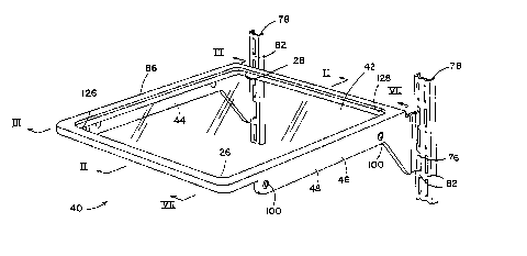
Referring to the drawing figures in greater detail, and Figures 1-4 in
particular, a shelf assembly 40 according to the present invention comprises a
generally planar shelf panel 42, support brackets 44 and 46, and a one piece member
or ellcaps~ ting cover 48 preferably formed from a moldable material as explained
below. Member 48 encap~ulates a perimeter edge 56 of panel 42 and a substantial
majority of the brackets 44, 46. Shelf assembly 40 is preferably cantilevered forward
by brackets 44 and 46 from a generally vertical surface, such as the rear wall of a
refrigerator, for example. Shelf assembly 40 may also be adapted for other support
structures, such as a sidewall for example. Shelf assembly 40 is preferably sized to
provide air circulation space between the shelf assembly and adjacent vertical surfaces
of the refrigerator for proper circulation.
Shelf panel 42 may be any suitable shelving material, including a light
tr~n~mitting material, for example, and is preferably about 0.130 inch (3.3 mm) thick,
21~s~o~
-
optically clear tempered glass to enhance light distribution through a refrigerated
co~ alLIllent. Perimeter edge 56 of shelf panel 42 is preferably located above
brackets 44 and 46 at two opposing sides of shelf assembly 40. Brackets 44 and 46
are mirror image replicas of one another and are uniformly incorporated in shelf5 assembly 40. Thus, bracket 44 will be discussed in greater detail with the
underst~n(ling that the discussion applies equally to bracket 46.
As shown in Figure 4, a flange portion 60 projects inwardly at a top edge of a
generally vertical web portion 64 of bracket 44. Flange 60 is provided with two
indexing apertures 66 and a series of fastening holes 68 (Figs. 3 and 23) to
10 mechanically connect bracket 44 with one piece member or ellcapsulating cover 48
(Figs. 3-6), as will be discussed in greater detail below. Web 64 is also provided
with two indexing apertures 70 and several molding holes 72 (Figs. 3 and 23).
Support bracket 44 may be fabricated of conventional materials by conventional
methods as is well known for adjustable shelving brackets. For a refrigerator
ellvirolllllent, bracket 44 is most preferably about fourteen gage (0.0781 inch, 1.98
mm) steel with a powder coat finish. One such fini~hing product which performs well
and is readily available, is commonly known as Herberts Epoxy Polyester 071-30-06
White, available from Herberts Powder Coatings, Inc. of Hilliard, Ohio.
While shelf assembly 40 may be used as a fixed shelf, shelf assembly 40 is
preferably used as a vertically adjustable shelf. Therefore, bracket 44 is provided
with a support body portion 74 and a support mount portion 76 (Fig. 3). Support
mount 76 is adapted for releasable engagement at a plurality of vertically spaced
positions with a support surface as may be provided by adjustable shelf tracks 78 (Fig.
1), as is commonly practiced. Thus, support mount 76 is preferably formed with
hooks 80 to engage rungs 82 in tracks 78 (Figs. 1 and 3). Shelf assembly 40 may,thereby, be positioned at a plurality of vertically spaced locations along tracks 78.
Encapsulating cover 48 is most preferably formed in one piece around
perimeter edge 56 of panel 42 and around at least a significant majority of the
brackets 44, 46, namely, support body portion 74 for tight connection of panel 42
with the brackets. One piece member 48 is formed from any suitable moldable
21~s~o~
``~`~-
material, including, but rlot limited to, structural, resinous plastics such as ABS,
polyvinyl chloride, or copolymers, such as a combination of ethylene and
poly~ro~ylene, for example. One readily available material which performs well and
meets FDA regulations for food pack~ging applications is Tenite~ Polypropylene
PSM4K-007, available from Eastman Chemical Products, Inc., a marketing ~ffili~te of
Eastman Kodak Compally. A coloration pigment may be added to the moldable
material from which one piece member 48 is formed in order to provide desired
colors. Tit~nillm dioxide may be added for a white coloration for example. In a
refrigerator shelf application of the invention, the materials used must, of course, be
FDA approved for food contact.
In the embodiment shown, one piece member 48 encapsulates perimeter edge
56, forming a rim 86, and el~ap~ulates support body portion 74, except for smallareas around the flange and web indexing apertures 66 and 70, respectively, with an
about 0.0787 inch (2 mm) thick ~h~thing (Figs. 1-6). Support mount 76 is not
ellcap~ulated by member 48, but remains uncovered to engage and releasably couple
with the adjustable shelf tracks 78, which are commonly used for adjustable shelving.
Thus, member 48 ellcapsulates a significant majority of the brackets 44, 46, but does
not entirely encapsulate the brackets. Portions not encapsulated include support mount
76; a first recess 90, and a second recess 92, each provided in member 48 at each
web in-l~xing aperture 70; and an index recess 94, provided at each flange indexing
aperture 66 (Fig. 5). The first and second recesses 90, 92 align with web indexing
ape,Lule 70 to define a fastening aperture 96 through shelf support bracket 44.
Shelf assembly 40 further includes a plug 100 which comprises a post 102 with
a head 104 and shaft 106 and a cooperating nut 108 (Figs. 4, 10, and 11). As will be
explained below, post 102 and nut 108 are useful in forming member 48 around thebrackets 44, 46. Post shaft 106 extends through a web indexing aperture 70 with post
head 104 positioned to abut one side of bracket web 64. Cooperating nut 108 is
formed with an aperture 110 to receive post shaft 106. Nut 108 is mounted on post
shaft 106 with the nut abutting bracket web 64 on a side opposite post head 104. Nut
108 may be an annular member and may optionally be formed with a skirt portion 112
21g8~o3
-
as shown in the embodiment of the drawing figures, with skirt portion 112 exten~ling
into web indexing apelLu~ 70, between bracket web 64 and post shaft 106. Post head
104 is seated in first recess 90, defined in member 48, while nut 108 is seated in
second recess 92, defined in member 48. While plug 100 is shown in the drawing
figures with post head 104 on the same side of bracket web 64 as bracket flange 60
and nut 108 is shown on a side of bracket web 64 opposite to bracket flange 60, the
respective positions of post head 104 and nut 108 may, of course, be interchanged, as
will occur to those who are skilled in the art and to those who pMctice the invention.
Similar to member 48, plug 100 may be formed from any suitable moldable
material, including, but not limited to, structural, resinous plastics such as ABS
polyvinyl chloride, or copolymers, for example, as (li~cucse-l more particularly above.
Depending upon the characteristics desired, plug 100 may be formed of the same
material as member 48 or may be formed of a material having contrasting properties
to those of the material for member 48, such as having a higher or lower temperature
melting point for example. The inventors have specifically found an acetal resinthermoplastic .,.:..k~t~cl under the trademark Delrin~ by EI Du Pont de Nemours &
Co~ ally to perform satisfactorily for plugs 100.
By the choice of material of plug 100 relative to the material for member 48,
plug 100 may be fused or effectively welded with member 48 or plug 100 may be
removable from member 48 and either of support brackets 44 and 46 to reveal
fastening apertures 96 so a storage device, for example, may be att~h~d to the
support bracket, such as a slide rail or guide 120 (Fig. 6) as disclosed in commonly
assigned United States Patent No. 5,273,354, entitled MOLDED REFRIGERATED
SHELF AND SUPPORT BRACKET and issued on December 28, 1993, to Herrmann
et al. Slide guide 120 may be att~rhpd by use of screws or bolts 122 at two spaced
positions along the length of web 64 as specifically shown in Figure 6, by riveting, or
by engagement of a fastening prong which extends into fastening aperture 96 fromslide guide 120 or the like as are commonly known for mounting or assembling
shelving components.
As discussed above, one piece member 48 encapsulates perimeter edge 56 of
-10-
2148403
-
panel 42 with a rim 86 (Figs. 1-6). Rim 86 is most preferably a perimeter rim which
surrounds perimeter edge 56 and extends above a top surface of shelf panel 42 todefine a spill dam and contain spills disposed upon shelf panel 42 as disclosed in
commonly ~si~n~d United States Patent 5,362,145, entitled MOLDED
REFRIGERATOR SHELF and issued on November 8, 1994, to Bird et al. By
molding rim 86 about perimeter edge 56, a liquid resistant seal is created between
shelf panel 42 and rim 86 to ~ e, if not entirely preclude, seepage of spills
between shelf panel 42 and rim 86. Depending upon the specific material used to
form one piece member 48 and rim 86, the seal may be enh:~nred by coating
perimeter edge 56, including the edge surface and adjoining portions of the top and
bottom surfaces of shelf panel 42, with a primer layer of a cooperating, heat activable
material or the like which promotes and facilitates adhesion of rim 56 to shelf panel
42, prior to forming rim 86 about perimeter edge 56.
Additional storage device attachment may be provided by forming at least one
front receptacle 126 in rim 86 at a front edge 234 of shelf panel 42 and at least one
cooperating back receptacle 128 in rim 86 at a back edge 236 of shelf panel 42 (Figs.
1 and 7).
In production, shelf assembly 40 may conveniently be molded in a mold 140
incorporating the features disclosed in Figures 8-15 and di~cussed below. Referring
more particularly to Figures 8 and 9, mold 140 generally includes a first or lower
mold half 142 and a second or upper mold half 144. In a closed position, with first
or lower mold half 142 abutting second or upper mold half 144, mold 140 forms a
mold cavity 180 which defines the configuration of the encapsulating cover or
sheathing of shelf assembly 40, generally discussed here as one piece member 48,including rim 86 (Figs. 8, 10, 13, and 14). Shelf panel 42 is positioned in mold 140
to extend at least partially into mold cavity 180. Those who are skilled in the art,
those who practice the invention, and those who otherwise have some f~mili~rity with
molding production technology will realize that, while some materials (includingmetals and some plastics, for example) suitable for shelf panel 42 may absorb
significant compressive loads when clamped in mold 140, other materials (such as
2l4s~o~
glass, for example) will accommodate only limited clamping loads in mold 140.
Thus, mold 140 should be adapted to the particular material of shelf panel 42 as is
well known in the molding industry.
As mentioned above, shelf assembly 40 may optionally be provided with front
and back slide guide receptacles 126 and 128 (Fig. 7), respectively, for in~t~ tion of
a slide guide 120 as is tli~c~lssed further in United States patent application Serial No.
07/912,778, referenced above. Thus, mold half 142 may be provided with recesses or
core beds 182 (Figs. 9 and 14) to receive sliding cores 184 to form the front slide
guide receptacle 126 and back slide guide receptacle 128, in front and back portions
of perimeter rim 86, respectively. Further, actl1~ting cylinders 186 may be mounted
on mold first half 142 with piston rods 188 e~elldillg through mold first half 142 into
core beds 182 to couple in sliding engagement with sliding cores 184 to positionsliding cores 184. Each sliding core 184 is positioned on and conn~ctecl with mold
half 142 by a cap bolt 190 (Figs. 9, 14, and 15) or the like, and is provided with an
elongated fastening slot 192 having a shoulder 194 so the core 184 is slidable in core
bed 182 and held in the core bed by bolt 190.
Each of shelf support brackets 44 and 46 is provided with a pair of plugs 100,
mounted in the two web indexing apertures 70 (Figs. 9-13). Mold 140 is opened bysepalalillg first half 142 and second half 144 so support brackets 44 and 46 may be
positioned on mold first half 142 by manual or automated means, with flange indexing
apertures 66 coupling with cooperating indexing pins 204. Each of shelf support
brackets 44 and 46 is most preferably fabricated of a magnetic material and may,therefore, be held in place on mold first half 142 by a rare earth magnet 205 (Fig. 9)
embedded in first half 142 as is commonly practiced and known in the molding
industry.
After the shelf support brackets 44 and 46 are positioned in the mold, or
~imlllt~n~ous to their positioning, shelf panel 42 is also positioned in mold first half
142 by manual or automated means, and may be held in mold 140 by conventional
methods. With the shelf support brackets 44, 46 and shelf panel 42 positioned onmold first half 142, mold 140 is closed by firmly abutting first half 142 and second
2 1 q 8 ~ O ~
half 144 together. Sliding cores 184 are preferably pulled ~ulw~ld into a molding
position by cylinders 186 prior to placing shelf panel 42, but are so positioned at least
prior to actual molding.
Second half 144 is also provided with ~ct~l~ting cylinders 206 (Figs. 8 and 9)
5 to manipulate a slide 208 and firmly clamp support mount portion 76 of each of shelf
support brackets 44 and 46 between slide 208 and mold first half 142 after mold 140
is closed or siml-lf~nP.ous with closing. With mold 140 closed and shelf supportbrackets 44 and 46 secured, the moldable material to form the encapsulating cover or
~h~thing and perimeter rim 86 of one piece member 48 is injected into mold cavity
180 by m~rhin~ry and passageways through mold 140 which are commonly known
and understood in the plastic molding industry. As the moldable material forming one
piece member 48 enters mold cavity 180 and flows through the mold cavity, the
material flows around perimeter edge 56 of shelf panel 42, flows around portions of
sliding cores 184 which extend into mold cavity 180, and flows around shelf support
brackets 44 and 46 until mold cavity 180 is filled with the moldable material. The
moldable material also flows through flange fastening holes 68 (Fig. 13) and webmolding holes 72 to make a secure mechanical connection between one piece member48 and shelf support brackets 44 and 46.
Without the presence of plugs 100 (Fig. 10), the flow of the moldable material
around the support brackets 44 and 46 may deflect the brackets causing them to twist
out of position. However, with plugs 100 in place, shelf support brackets 44 and 46
are tightly clamped and securely positioned between plug post head 104 and nut 108,
which in turn are clamped between mold first half 142 and second half 144.
After the moldable material forming one piece member 48 is allowed to set-up,
harden, and cool, mold 140 is opened. Cylinders 186 are activated concurrent with
opening mold 140 cylinders 186 are activated to slide sliding cores 184 inward and
clear of mold cavity 180 and newly formed perimeter rim 86. Once mold 140 opens,shelf assembly 40 is removed from the mold.
In production and as is also well known in the molding industry, mold 140 will
be provided with means for cooling and heating such as a water circulation system, to
~_ 21~8~3
initially heat the mold to a desired steady state operating temperature prior to starting
a production run and to m~int~in the mold at that desired production temperaturethroughout the duration of the production run of shelf assembly 40. Thus, depending
on a number of production factors, including ambient temperature and the cycling5 time of mold 140, for example, the mold may require supplemental heating or cooling
throughout the production run to m~int~in the desired production temperature.
Shelf assembly 40 may be a relatively narrower shelf assembly for use in the
relatively narrower colllpalllllents of a side-by-side refrigerator or as a partial width
shelf in a colllpalllllent of a top or a bottom mount refrigerator.
10Shelf assembly 40 may also be a relatively wider shelf assembly as is more
specifically shown in Figure 16 as an elongated shelf assembly 230, provided
according to this invention for a full width shelf in a top or a bottom mount
refrigerator or the like. Because of the extended width of shelf assembly 230, anti-
sagging reinforcement may be included. Thus, shelf assembly 230 may further be
15provided with a ~lirÇe~ g channel 232 (Figs. 17 and 18) wrapped around at least a
front edge 234 of shelf panel 42. Stiffening channel 232 may be extruded from 1018
cold-rolled steel or otherwise formed to create an elongated, open-sided channelmember, sized to snugly slip-fit over the front edge 234 of shelf panel 42. While
~irrenillg channel 234 is depicted in the drawing figures with a stylized "G" section or
20 profile, those who are skilled in the art and those who practice the invention will
appreciate the fact that numerous allelll~liv~ profiles, including, but not limited to,
"E", "F", and "S" or "Z" shapes, for example, may be used to develop the required
greater section modulous along the front edge 234 of shelf panel 42 to resist vertical
loading deflection and, llltim~tely, fracture or failure. They will also appreciate that
25 ~lirrel~illg channel 232 may be formed of various, readily available structural
materials, including, plastics as well as metals, for example, and may be formed by
various, readily available methods. To ~ e potential corrosion of ~lirÇel~illg
channel 232, the channel is most preferably E-coated according to common
automotive industry fini~hing standards, including the process of an ionized washed
30 steel step, a zinc phosphate dip, electrostatic painting, and curing or baking at about
-14-
21~8~03
`:~
three hundred eighty to four hundred ten degrees Fahrenheit.
A ~,~irrenillg channel 232 may also be provided along a back edge 236 of shelf
panel 42. However, a center support bracket 240 (Figs. 17 and 19-22) is preferably
provided instead. Bracket 240 may be conveniently formed from two symmetrical ormirror image pieces stamped from sixteen gage steel and spot welded together, for
example. For refrigerator shelving use, bracket 240 may typically be provided with a
white powder-coat finish as (li~cll~se~l in greater detail above regarding shelf support
brackets 44 and 46. Bracket 240 has a body portion 242 which extends lealw~rd to a
double hook arrangement 244 to mate with a two row adjustable shelf track 78 or the
like, commonly found as a center of three shelf tracks provided in contemporary top
or bottom mount refrigerators. Of course, the configuration of bracket 240 in
consideration of releasable engagement with an adjustable shelf track will be dictated
by the particular shelving arrangement and, specifically, the shelf track with which
bMcket 240 will releasably couple. In front elevation, bracket 240 presents a general
T-shape with a pair of opposing flanges 246 extending from a top edge of the body
portion 242 or web portion. Each flange 246 is provided with a locking device, such
as a barb 248, for example, to resist withdrawal of bracket 240 from the molded rim
86 of shelf assembly 230 after assembly of bracket 240 with shelf assembly 230.
A coopcl~ g dowl~w~rd and le~l~,vdrd opening bracket slot 250 (Figs. 19 and
20) is provided in rim 86 and generally centered along back edge 236 of shelf
assembly 230. Bracket slot 250 has a cooperating main slot or horizontal portion 252
oriented generally parallel to shelf panel 42 and spaced vertically below the shelf
panel to receive flanges 246. Horizontal slot 252 opens to the back of shelf assembly
230 and is sized for force-fit engagement with flanges 246 to assure that the locking
device of bracket 240, namely, barbs 248 in the embodiment shown, is effective in
securing bracket 240 and resisting disassembly. Bracket slot 250 also has a stemportion 254 extending and opening generally dowllwal.l from horizontal slot 252 to
accept the web or body 242 of bracket 240 when flanges 246 engage and seat in
horizontal slot 252.
In allclllalive molding of shelf assembly 40, mold stand-offs 260 which project
2148~03
,
into mold cavity 180 may be provided to abut web 64 of shelf support bracket 44
(Fig. 26) in combination with the use of plug post 102, without plug nut 108, to index
and secure shelf support bracket 44. The shaft 106 of post 102 may extend full length
as ~ cllcce~l above and shown in Figure 26 to provide a fastening aperture through
S one piece member 48 and shelf support bracket 44. Allellldlively, post shaft 106 may
be shortened to only extend into web indexing aperture 70, reslll~ing in a shelfassembly as depicted in Figures 23 and 24. Of course, those skilled in the art and
those who practice the invention will realize that the relative positions of plug post
102 and mold stop 260 may be interchanged as shown in Figure 25, depending upon
the specific configuration desired and application of the shelf assembly intended. The
post 102 of Figure 26 may also be replaced with a draw pin as is known in the
molding field, to index and space bracket 44. It will further be appreciated that
flange index pins 204 may be modified to accept another post 102 to mold a shelfassembly according to the invention in a configuration similar to that shown in Figures
27 and 28. In such case, cylin-lric~l tubes or sleeves 270 are substituted for index
pins 204, while posts 102 are fitted in indexing apertures 66 of support flange 60 with
enlarged heads 104 forming spacers eng~ging and sepaldlillg edge 56 of panel 42 and
the top surface of flange 60. The shafts 106 of posts 102 project into sleeves 270 to
firmly position the bracket in the mold cavity. Of course, posts 102, when used in
such lllal~lel, will remain p~llllallelllly embedded within the shelf between panel 42
and the support bracket.
It will otherwise be generally understood by those who practice the invention
and by those skilled in the art, that various other modifications and improvements may
be made to the invention without departing from the spirit of the disclosed concept.
The scope of protection afforded is to be d~l~llllhled by the claims and by the breadth
of h~ lelalion allowed by law.
-16-