Some of the information on this Web page has been provided by external sources. The Government of Canada is not responsible for the accuracy, reliability or currency of the information supplied by external sources. Users wishing to rely upon this information should consult directly with the source of the information. Content provided by external sources is not subject to official languages, privacy and accessibility requirements.
Any discrepancies in the text and image of the Claims and Abstract are due to differing posting times. Text of the Claims and Abstract are posted:
| (12) Patent: | (11) CA 2148521 |
|---|---|
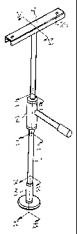
| (54) English Title: | A SUPPORT POLE WITH PIVOTING AND LOCKING HANDRAIL FOR ELDERLY AND DISABLED PERSONS |
| (54) French Title: | TIGE DE SOUTIEN AVEC MAIN COURANTE PIVOTANTE ET VERROUILLABLE POUR PERSONNES AGEES ET PERSONNES HANDICAPEES |
| Status: | Term Expired - Post Grant Beyond Limit |
| (51) International Patent Classification (IPC): |
|
|---|---|
| (72) Inventors : |
|
| (73) Owners : |
|
| (71) Applicants : |
|
| (74) Agent: | |
| (74) Associate agent: | |
| (45) Issued: | 2002-05-21 |
| (22) Filed Date: | 1995-05-03 |
| (41) Open to Public Inspection: | 1996-11-04 |
| Examination requested: | 1999-04-23 |
| Availability of licence: | N/A |
| Dedicated to the Public: | N/A |
| (25) Language of filing: | English |
| Patent Cooperation Treaty (PCT): | No |
|---|
| (30) Application Priority Data: | None |
|---|
A support pole for elderly and disabled persons having a pivoting and locking horizontal handrail. It comprises a telescopic pole adapted to be vertically fixed between the floor and ceiling of a room and a horizontal handrail pivotally mounted thereon. A castellated collar and an engaging pin which is actuated by the handrail to move about the pole in small safe increments. The device is to be used by elderly or disabled persons to move from one position to another independent of any assistance.
Un poteau de soutien pour personnes âgées et handicapées, muni d'une main courante horizontale pivotante et bloquante. Il se compose d'un poteau télescopique adapté pour être fixé verticalement entre le plancher et le plafond de la pièce, d'une main courante horizontale montée par pivotement sur celui-ci, d'un collier crénelé et d'une goupille d'engagement actionnée par la main courante pour se déplacer autour du poteau par mouvements incrémentiels limités et surs. Ce dispositif est conçu pour permettre à des personnes âgées et handicapées de se déplacer d'une position à une autre sans nécessiter aucune assistance.
Note: Claims are shown in the official language in which they were submitted.
Note: Descriptions are shown in the official language in which they were submitted.
2024-08-01:As part of the Next Generation Patents (NGP) transition, the Canadian Patents Database (CPD) now contains a more detailed Event History, which replicates the Event Log of our new back-office solution.
Please note that "Inactive:" events refers to events no longer in use in our new back-office solution.
For a clearer understanding of the status of the application/patent presented on this page, the site Disclaimer , as well as the definitions for Patent , Event History , Maintenance Fee and Payment History should be consulted.
| Description | Date |
|---|---|
| Inactive: Expired (new Act pat) | 2015-05-03 |
| Maintenance Request Received | 2014-03-05 |
| Maintenance Request Received | 2013-02-27 |
| Inactive: Office letter | 2011-07-20 |
| Inactive: Reversal of will be deemed expired status | 2011-07-20 |
| Letter Sent | 2011-05-03 |
| Inactive: Office letter | 2010-06-04 |
| Change of Address Requirements Determined Compliant | 2010-06-04 |
| Inactive: Late MF processed | 2009-11-19 |
| Letter Sent | 2009-05-04 |
| Inactive: Late MF processed | 2008-04-14 |
| Inactive: Adhoc Request Documented | 2008-02-06 |
| Letter Sent | 2007-05-03 |
| Inactive: IPC from MCD | 2006-03-11 |
| Inactive: Cover page published | 2005-06-14 |
| Inactive: Cover page published | 2005-05-11 |
| Inactive: Office letter | 2004-10-04 |
| Inactive: Office letter | 2004-10-04 |
| Letter Sent | 2004-10-04 |
| Inactive: Protest/prior art received | 2004-02-23 |
| Inactive: Adhoc Request Documented | 2004-02-23 |
| Inactive: Adhoc Request Documented | 2004-01-05 |
| Amendment Received - Voluntary Amendment | 2003-12-18 |
| Re-examination Started | 2003-07-02 |
| Re-examination Request | 2003-06-03 |
| Re-examination Started | 2003-06-03 |
| Grant by Issuance | 2002-05-21 |
| Inactive: Cover page published | 2002-05-20 |
| Inactive: Final fee received | 2002-02-25 |
| Small Entity Declaration Determined Compliant | 2002-02-25 |
| Pre-grant | 2002-02-25 |
| Notice of Allowance is Issued | 2002-02-12 |
| Letter Sent | 2002-02-12 |
| Notice of Allowance is Issued | 2002-02-12 |
| Inactive: Approved for allowance (AFA) | 2002-01-23 |
| Inactive: Status info is complete as of Log entry date | 1999-05-20 |
| Letter Sent | 1999-05-20 |
| Inactive: Application prosecuted on TS as of Log entry date | 1999-05-20 |
| Request for Examination Requirements Determined Compliant | 1999-04-23 |
| All Requirements for Examination Determined Compliant | 1999-04-23 |
| Inactive: Inventor deleted | 1998-06-23 |
| Inactive: Inventor deleted | 1998-06-23 |
| Inactive: Inventor deleted | 1998-06-23 |
| Inactive: Applicant deleted | 1998-06-23 |
| Inactive: Applicant deleted | 1998-06-23 |
| Inactive: Inventor deleted | 1998-06-23 |
| Inactive: Inventor deleted | 1998-06-23 |
| Inactive: Applicant deleted | 1998-06-23 |
| Inactive: Inventor deleted | 1998-06-23 |
| Inactive: Reversal of dead status | 1998-06-19 |
| Inactive: Delete abandonment | 1998-06-18 |
| Time Limit for Reversal Expired | 1998-05-04 |
| Deemed Abandoned - Failure to Respond to Maintenance Fee Notice | 1997-05-05 |
| Application Published (Open to Public Inspection) | 1996-11-04 |
| Abandonment Date | Reason | Reinstatement Date |
|---|---|---|
| 1997-05-05 |
The last payment was received on 2002-02-21
Note : If the full payment has not been received on or before the date indicated, a further fee may be required which may be one of the following
Please refer to the CIPO Patent Fees web page to see all current fee amounts.
Note: Records showing the ownership history in alphabetical order.
| Current Owners on Record |
|---|
| JOHN L. O'BRIEN |
| DONALD A. N. ED |
| EDWARD M. THOMAS |
| Past Owners on Record |
|---|
| None |

