Language selection

Search

Patent 2148567 Summary

Third-party information liability

Some of the information on this Web page has been provided by external sources. The Government of Canada is not responsible for the accuracy, reliability or currency of the information supplied by external sources. Users wishing to rely upon this information should consult directly with the source of the information. Content provided by external sources is not subject to official languages, privacy and accessibility requirements.

Claims and Abstract availability

Any discrepancies in the text and image of the Claims and Abstract are due to differing posting times. Text of the Claims and Abstract are posted:

  • At the time the application is open to public inspection;
  • At the time of issue of the patent (grant).
(12) Patent: (11) CA 2148567
(54) English Title: ARRANGEMENT IN AN OPENING IN THE WALL OF AN ELEVATOR SHAFT AND INSTRUMENT PANEL
(54) French Title: LOGEMENT DU TABLEAU DE BORD DANS UNE OUVERTURE DE LA PAROI D'UN PUITS D'ASCENSEUR
Status: Expired and beyond the Period of Reversal
Bibliographic Data
(51) International Patent Classification (IPC):
  • B66B 7/00 (2006.01)
  • B66B 11/00 (2006.01)
  • B66B 13/30 (2006.01)
(72) Inventors :
  • HAKALA, HARRI (Finland)
  • MUSTALAHTI, JORMA (Finland)
  • AULANKO, ESKO (Finland)
(73) Owners :
  • KONE OY
(71) Applicants :
  • KONE OY (Finland)
(74) Agent: G. RONALD BELL & ASSOCIATES
(74) Associate agent:
(45) Issued: 2002-07-16
(22) Filed Date: 1995-05-03
(41) Open to Public Inspection: 1995-11-05
Examination requested: 1998-08-12
Availability of licence: N/A
Dedicated to the Public: N/A
(25) Language of filing: English

Patent Cooperation Treaty (PCT): No

(30) Application Priority Data:
Application No. Country/Territory Date
FI 942063 (Finland) 1994-05-04

Abstracts

English Abstract

The instrument panel of an elevator is placed in the same opening in the wall of the elevator shaft as the landing door of the elevator. The instrument panel contains elevator control equipment and the electric drive controlling the hoisting motor of the elevator. The instrument panel of the elevator is connected to the jamb structure of the landing door.


French Abstract

Le tableau de bord d'un ascenseur est placé dans la même ouverture de la paroi du puits d'ascenseur que la porte palière de l'ascenseur. Le tableau de bord contient un équipement de commande d'ascenseur et l'entraînement électrique commandant le moteur de levage de l'ascenseur. Le tableau de bord de l'ascenseur est relié à la structure de montant de la porte palière.

Claims

Note: Claims are shown in the official language in which they were submitted.

THE EMBODIMENTS OF THE INVENTION IN WHICH AN EXCLUSIVE
PROPERTY OR PRIVILEGE IS CLAIMED ARE DEFINED AS FOLLOWS:
1. An integrating arrangement for an automated elevator having
a landing door extending in an opening in one wall of an elevator shaft,
wherein
an instrument panel of the elevator, containing elevator control equipment and
an
electric drive controlling a hoisting motor of the elevator, is positioned in
the same
opening as the door.
2. An arrangement as in claim 1, wherein the instrument panel
is covered with a cover which can be opened from the landing and consists of
one
or more parts.
3. An arrangement as in claim 1 or 2, wherein the instrument
panel has a connected window or latch through which the elevator shaft is
visible
from the landing.
4. An instrument panel for an automated elevator having a door
on a landing, the instrument panel containing an electric drive controlling a
hoisting motor of the elevator and also containing elevator control equipment,
wherein the instrument panel is rigidly mounted in an integrating arrangement
for
the automatic elevator so as to be fixed in position relative to a wall of the
elevator
shaft and a jamb structure of the elevator door.
5. An instrument panel as in claim 4, wherein the instrument
panel is integrally connected with the jamb structure of the elevator door.
6. An instrument panel as in claim 4, wherein the panel has a
cover and a lock for locking the cover in position.
7. An instrument panel as in claim 5, wherein the panel has a
cover and a lock for locking the cover in position.

8. An instrument panel as in any one of claims 4, 5, 6 or 7,
wherein the panel comprises in part a window which, at least when the cover
is open, provides visibility through the panel.
9. An instrument panel as in any one of claims 4, 5, 6 or 7,
wherein the panel has fire insulation.
10. An instrument panel as in any one of claims 4, 5, 6 or 7,
wherein the panel comprises in part a window which, at least when the cover
is open, provides visibility through the panel, and wherein the panel has fire
insulation.
11. An instrument panel as in any one of claims 4, 5, 6 or 7,
wherein the panel has noise insulation for isolating the landing from shaft
space
noise.
12. An instrument panel as in any one of claims 4, 5, 6 or 7,
wherein the panel comprises in part a window which, at least when the cover
is open, provides visibility through the panel, and wherein the panel has
noise
insulation for isolating the landing from shaft space noise.
13. An instrument panel as in any one of claims 4, 5, 6 or 7,
wherein the panel comprises in part a window which, at least when the cover
is open, provides visibility through the panel, wherein the panel has fire
insulation, and wherein the panel has noise insulation for isolating the
landing
from shaft space noise.
14. An instrument panel as in any one of claims 4, 5, 6 or 7,
wherein the panel has fire insulation that consists of a mineral wool sheet
lining
placed on a jamb structure wall facing towards the landing.

15. An instrument panel as in any one of claims 4, 5, 6 or 7,
wherein the panel comprises in part a window which, at least when the cover
is open, provides visibility through the panel, and wherein the panel has fire
insulation that consists of a mineral wool sheet lining placed on a jamb
structure
wall facing towards the landing.
16. An instrument panel as in any one of claims 4, 5, 6 or 7,
wherein the panel has noise insulation for isolating the landing from shaft
space
noise, the noise insulation consisting of a mineral wool sheet lining placed
on
a jamb structure wall facing towards the landing.
17. An instrument panel as in any one of claims 4, 5, 6 or 7,
wherein the panel comprises in part a window which, at least when the cover
is open, provides visibility through the panel, and wherein the panel has
noise
insulation for isolating the landing from shaft space noise, the noise
insulation
consisting of a mineral wool sheet lining placed on a jamb structure wall
facing
towards the landing.
18. An instrument panel as in any one of claims 4, 5, 6 or 7,
wherein the panel comprises in part a window which, at least when the cover
is open, provides visibility through the panel, wherein the panel has fire
insulation, and wherein the panel has noise insulation for isolating the
landing
from shaft space noise, the fire insulation or the noise insulation consisting
of
a mineral wool sheet lining placed on a jamb structure wall facing towards the
landing.
19. An instrument panel as in any one of claims 4, 5, 6 or 7,
wherein the panel comprises in part a window which, at least when the cover
is open, provides visibility through the panel, wherein the panel has fire
insulation, and wherein the panel has noise insulation for isolating the
landing
from shaft space noise, the fire insulation and the noise insulation each
consisting of a mineral wool sheet lining placed on a jamb structure wall
facing
towards the landing.

20. An arrangement in an opening for an automatic elevator
landing door in a wall of an elevator shaft, the landing door being in an
opening
for the elevator and being positioned in a plane when in a closed position,
the
arrangement comprising an instrument panel for the elevator, the instrument
panel containing elevator control equipment, an access opening with a window
and a drive for controlling a hoisting motor of the elevator, the instrument
panel
being placed in the opening with the landing door of the elevator and being
spaced from the plane in which the landing door is positioned when the landing
door is in the closed position such that the elevator is on one side of the
plane
and the instrument panel is on an opposite side of the plane, the instrument
panel being rigidly mounted in the arrangement so as to be fixed in position
relative to the wall of the elevator shaft and the instrument panel and window
preventing ready access to the elevator shaft.
21. The arrangement for an elevator according to claim 20,
wherein the landing door is movable in the plane from the closed position to
an
open position and wherein the landing door is between the elevator and the
instrument panel when the landing door is in the open position.
22. The arrangement for an elevator according to claim 20,
wherein the elevator shaft is visible through the window, the access opening
being spaced from the elevator control equipment in the instrument panel.
23. The arrangement for an elevator according to claim 22,
wherein the window is positioned in an upper part of the instrument panel.
24. The arrangement for an elevator according to claim 20, further
comprising an openable cover for the instrument panel.
25. The arrangement for an elevator according to claim 24, further
comprising a lock provided on the cover, the cover being movable between an
open position providing access to at least the instrument panel and a closed

position covering the at least the instrument panel, the lock latching the
door in
the closed position.
26. The arrangement for an elevator according to claim 24,
wherein the cover is movable between an open position providing access to at
least the instrument panel and a closed position covering the at least the
instrument panel and the window.
27. The arrangement for an elevator according to claim 20,
wherein the landing door has a door jamb structure and wherein at least the
instrument panel is integrated as a part of the door jamb structure.
28. The arrangement for an elevator according to claim 20, further
comprising fireproofing in the instrument panel.
29. The arrangement for an elevator according to claim 28,
wherein the fireproofing comprises a mineral wool sheet lining placed on a
jamb
structure wall facing towards a landing for the elevator.
30. The arrangement for an elevator according to claim 20, further
comprising noise insulating means provided in the instrument panel for
isolating
a landing of the elevator from the shaft.
31. The arrangement for an elevator according to claim 30,
wherein the noise insulating means comprises a mineral wool sheet lining
placed on a jamb structure wall facing towards the landing for the elevator.
32. The arrangement for an elevator according to claim 20,
wherein the instrument panel is in front of the elevator when the elevator is
adjacent the landing door.

Description

Note: Descriptions are shown in the official language in which they were submitted.


21~567
ARRANGEMENT IN AN OPENING IN THE WALL OF
AN ELEVATOR SHAFT AND INSTRUMENT PANEL
The present invention relates to the positioning of an instrument
5 panel for an elevator, more particularly, to an arrangement in which an
instrument panel is placed into an opening in the wall of an elevator shaft.
One objective in the development of elevators has been efficient
and economic utilization of building space. In the case of conventional traction-
sheave-driven elevators, the elevator machine room or other space designed for
10 the i"st~ lion of the drive machinery takes up a significant portion of the
building space needed for the elevator. To save space in the building, elevator
machinery solutions employing a flat construction in the direction of the shaft of
the lldctiGn sheave of the elevator have been proposed lately. Because of the
flat construction of the elevator machinery, the hoisting machinery can easily be
insta"~d in the elevator shaft. Finnish Patent Publicalioi~ Fl B 93939 (Kone
Corporation, published March 15, 1995) describes elevator machinery of this
type. Placing the instrument panel containing the elevator control system and
the power electronics driving the hoisting machinery in the elevator shaft is
technically possil,le, but in respect of maintenance and installation it would be
advantageous if the instrument panel were more readily accessP-le than it is
when placed in the elevator shaft. Similarly, the possibility to carry out minoroperations on the machinery without entering the elevator shaft would be an
advantage.
Swedish Publication SE B 332698 (ASEA AB, published February
15, 1971) discloses an arrangement in which certain hydraulic elevator control
circuits are placed at the landing beside a turn-door-type landing door. The
construction is such that the turn door can't be replaced with an automatic door,
because in that construction the automatic landing door has no room for its
opening movement.
To provide a solution to the need described above, the inventive
arrangement has an opening in the wall of an elevator shaft and a new type of

2lq8567
instrument panel for an elevator. In one form the invention is an integrating
arrangement for an aulo",dled elevator having a landing door extending in an
opening in one wall of an elevator shaft, wherein an instrument panel of the
elevator, containing elevator control equipment and an electric drive controlling
a hoisting motor of the elevator, is positioned in the same opening as the door.The instrument panel may be covered with a cover which can be opened from
the landing and consists of one or more parts. The panel may have a
connected window or latch through which the elevator shaft is visible from the
landing. In another form the invention is an instrument panel for an automated
elevator having a door on a landing, the instrument panel containing an electricdrive controlling a hoisting motor of the elevator and also containing elevator
control equipment, wherein the instrument panel is connected with a jamb
structure of the elevator door. The instrument panel may be integrally
connected with the jamb structure of the elevator door, and may have a cover
and a lock for locking the cover in position. The panel may comprise in part a
window which, at least when the cover is open, provides visibility through the
panel. The panel may also have fire insulation. The panel may further have
noise insulation for isolating the landing from shaft space noise. Either the fire
insul~tion or the noise insulation, or both, may consist of a mineral wool sheetlining placed on a jamb structure wall facing towards the landing.
The advantages achieved by the invention include the following:
- The working space to be provided in front of the instrument panel as
required e.g. by elevator regulalions or equivalent can be easily achieved.
- The use of the relatively slim control panel does not cause bigger
2 5 changes to the structural or functional features of the standard automatic
landing door.
- An a"angelllent for visual observation of the hoisting machinery through
the instrument panel is simple to realize.
- The instrument panel of the invention is especially applicable in rope-
driven elevators using a hoisting machinery placed in the elevator shaft.

21~856~
- The instrument panel can be provided with a hatch or equivalent through
which it is possible, if permitted by the rest of the elevator lay-out, to carryout ordinary checks and operations on the machinery, such as
checking/adjusl",ent of the brake, manual release of the brake, checking
the ropes and the traction sheave, possible manual operation of the
elevator etc.
- The lan.Jing on which the instrument panel is installed does not
significantly differ from other landings in respect of appearance.
- The invention makes in unnecessary to provide a space for a machine
room in the building.
- The solution of the invention does not require any extra apertures in the
shaft wall as the instrument panel can be placed in the same opening
with the landing door.
- The placement of the instrument panel in the door jamb structure is
particularly advantageous in respect of electrification of the elevator.
- Being provided with a lock, the instrument panel is safe.
- The instrument panel can be provided with a space for documents
pertaining to the elevator, e.g. drawings and a maintenance record.
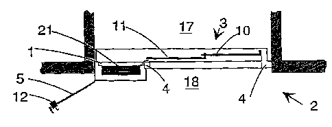
In the following, the invention is described by the aid of some
embodiments, referring to the attached drawings, in which:
Figure 1 is a front view of the inventive arrangement, as seen from the landing;Figure 2 is a cross-sectional top view of the door and instrument panel in an
opening between a landing and the elevator shaft; and
Figure 3 is a more detailed view of the left portion of Figure 2.
Figure 1 presents an arrangement according to the invention as
seen from the landing and with the cover 5 of the instrument panel 1 removed.
Figure 2 presents a cross-sectional top view of the door 3 and instrument panel
1 in an opening 2 between a landing 18 and the elevator shaft 17. The
instrument panel 1 is an assembly containing at least the electric drive
controlling the hoisting motor, as well as elevator control equipment. The
instrument panel 1 is placed in the same opening 2 between the landing and the

2lq~67
elevator shaft as the door and is incorporated in the jamb structure 4
surrounding the door, being connected to it with a contact achieved e.g. by
attaching the instrument panel 1 to the door jamb structure 4 or via common
parts shared by the instrument panel 1 and the door jamb structure 4. In this
5 context, the door jamb structure 4 is understood to be an assembly which, in
addition to the visible parts surrounding the door 3 and the structures needed
to retain these parts in place, may comprise the door frame and other
conventional door supporting structures in the opening 2 or in its immediate
vicinity. In front of the instrument panel 1 there is a sufficient working space on
10 the landing to allow, for example, a serviceman to service the elevator. Fromthe instrument panel 1, the service",dn can also see the hoisting machinery
through a window 6. The window may be an open aperture or a non-openable
window provided with a glass pane or a net, or it may also be implemented as
an openable hatch, in which case it may be either transparent or non-
15 transparent. Through an open aperture or openable hatch it is possible to~ccess, for example, the machinery 7 in the elevator shaft, the brake, manual
brake release lever 8, ropes 9 and the traction sheave of the machinery. The
window 6 may be part of the instrument panel 1, in which case looking through
the window means looking through the instrument panel, or the window may be
20 placed in some other suitable location, e.g. in the door jamb structure 4 above
the door. As to its appearance, the landing on which the instrument panel is
installed is like the other landings. The cover 5 may protrude from the opening
2 somewhat more than the door jamb sheets in the corresponding area on the
other floors. This is because the instrument panel 1 cannot be sunk very deep
25 into the jamb structure as there must be enough space behind the instrument
panel 1 to permit movement of the door leaves 10, 11. In fact, the placement
of the instrument panel could well be described by saying that the instrument
panel is placed inside the jamb structure, under a cover 5 comprised in the jambstructure. Thus, no separate machine room is needed in the building, as the
3 0 hoisting machinery 7 is placed in the elevator shaft and the instrument panel 1
in the door jamb structure. The cover 5 may be removable, or it may be so

21485~7
hinged that it can be turned aside off the instrument panel 1, as shown in Figure
2. The cover may have a construction consisting of one or more parts, and it
is prererably provided with a lock 12 to allow it to be locked in place. The
cables to be connected to the instrument panel 1 can easily be laid in the
5 elevator shaft 17. These cables include the conductors supplying electricity to
the instrument panel and also extending from the instrument panel to the
ele~;t,u,,,otor driving the machinery, as well as the wiring between the elevator
control system and the signal devices 13 and call buttons 14. The elevator
controller 21, electric drive 22, main switch 23, emergency operating buttons 2410 and other devices in the instrument panel 1 are accessP~le when the cover 5 is
open.
Figure 3 presents a more detailed view of a door jamb structure
containing an instrument panel. The jamb structure is lined with a fireproof
material 27, preferably, for example, mineral wool sheets, which, in addition to15 being fireproof, has a noise insulating capability. The lining of the jamb
structure is so designed with respect to fire lesislance and noise insulation that
it corresponds at least to the fire resistance and noise insulating capability of
landing doors. The cover is suspended on the jamb structure by means of a
hinge 28. On the side facing towards the landing 18, the space between the
2 o jamb structure and the cover 5 is protected with a body 29 attached to the jamb
structure and covering the gap between the jamb structure and the cover. Since
the fire cell division achieved through the placement of the fireproof material
follows the landing-side wall of the jamb structure and of the cover of the
instrument panel placed in it, the instrument panel need not be ins~ ted from
25 the shaft space 17 and ventilation of the instrument panel via the shaft space
is simple to achieve. The fire cell division can also be implemented in another
way, for instance by placing the fireproof lining on the shaft-side wall of the jamb
structure containing the instrument panel.
It should be obvious to a person skilled in the art that different
30 embodiments of the invention are not resl,i~;ted to the examples described

2198567
above, but that they may instead be varied within the scope of the following
claims.
It should also be obvious to the person skilled in the art that the
applicability of the invention is not re~l, icted to elevators of the type presented
5 in the above-mentioned Finnish Patent Publicdlion Fl B 93939, but that the
invention can be applied to other basic elevator solutions, e.g. elevators in
which the drive machinery is placed in the counterweight.
It should be further obvious to the skilled person that "instrument
panel" may refer to an instrument cabinet mounted on the door jamb structure
10 and containing the electric drive controlling the hoisting motor of the elevator
and the elevator control equipment, or for example, an assembly comprising two
instrument cabinets mounted in the door jamb structure and containing the
electric drive in one cabinet and the elevator control equipment in the other.

Representative Drawing
A single figure which represents the drawing illustrating the invention.
Administrative Status

2024-08-01:As part of the Next Generation Patents (NGP) transition, the Canadian Patents Database (CPD) now contains a more detailed Event History, which replicates the Event Log of our new back-office solution.

Please note that "Inactive:" events refers to events no longer in use in our new back-office solution.

For a clearer understanding of the status of the application/patent presented on this page, the site Disclaimer , as well as the definitions for Patent , Event History , Maintenance Fee  and Payment History  should be consulted.

Event History

Description Date
Time Limit for Reversal Expired 2014-05-05
Letter Sent 2013-05-03
Inactive: IPC from MCD 2006-03-11
Grant by Issuance 2002-07-16
Inactive: Cover page published 2002-07-15
Pre-grant 2002-04-05
Inactive: Final fee received 2002-04-05
Amendment After Allowance Requirements Determined Compliant 2001-11-21
Letter Sent 2001-11-21
Amendment After Allowance (AAA) Received 2001-11-07
Notice of Allowance is Issued 2001-10-16
Letter Sent 2001-10-16
Inactive: Approved for allowance (AFA) 2001-09-28
Amendment Received - Voluntary Amendment 2000-11-07
Inactive: S.30(2) Rules - Examiner requisition 2000-08-21
Amendment Received - Voluntary Amendment 1999-08-12
Inactive: Application prosecuted on TS as of Log entry date 1998-09-11
Inactive: RFE acknowledged - Prior art enquiry 1998-09-11
Inactive: Status info is complete as of Log entry date 1998-09-11
Request for Examination Requirements Determined Compliant 1998-08-12
All Requirements for Examination Determined Compliant 1998-08-12
Deemed Abandoned - Failure to Respond to Maintenance Fee Notice 1997-05-05
Inactive: Adhoc Request Documented 1997-05-05
Application Published (Open to Public Inspection) 1995-11-05

Abandonment History

Abandonment Date Reason Reinstatement Date
1997-05-05

Maintenance Fee

The last payment was received on 2002-04-25

Note : If the full payment has not been received on or before the date indicated, a further fee may be required which may be one of the following

  • the reinstatement fee;
  • the late payment fee; or
  • additional fee to reverse deemed expiry.

Please refer to the CIPO Patent Fees web page to see all current fee amounts.

Owners on Record

Note: Records showing the ownership history in alphabetical order.

Current Owners on Record
KONE OY
Past Owners on Record
ESKO AULANKO
HARRI HAKALA
JORMA MUSTALAHTI
Past Owners that do not appear in the "Owners on Record" listing will appear in other documentation within the application.
Documents

To view selected files, please enter reCAPTCHA code :


To view images, click a link in the Document Description column. To download the documents, select one or more checkboxes in the first column and then click the "Download Selected in PDF format (Zip Archive)" or the "Download Selected as Single PDF" button.

List of published and non-published patent-specific documents on the CPD .

If you have any difficulty accessing content, you can call the Client Service Centre at 1-866-997-1936 or send them an e-mail at CIPO Client Service Centre.


Document
Description 
Date
(yyyy-mm-dd) 
Number of pages   Size of Image (KB) 
Abstract 1995-11-05 1 10
Cover Page 1996-07-02 1 16
Description 1995-11-05 6 279
Claims 1995-11-05 3 113
Drawings 1995-11-05 2 33
Cover Page 2002-06-11 1 35
Claims 2000-11-07 5 205
Claims 1999-08-12 5 197
Representative drawing 2001-10-01 1 10
Representative drawing 1998-08-05 1 16
Acknowledgement of Request for Examination 1998-09-11 1 177
Commissioner's Notice - Application Found Allowable 2001-10-16 1 166
Maintenance Fee Notice 2013-06-14 1 170
Correspondence 2002-04-05 1 23
Fees 1998-04-21 1 44
Fees 2000-04-25 1 45
Fees 2002-04-25 1 38
Fees 2001-04-25 1 44
Fees 1999-04-23 1 42
Fees 1997-04-28 1 45