Note: Descriptions are shown in the official language in which they were submitted.
2148~~9
-1-
PATENT
60617
1 SNOWSHOE
2 ~ Backctround of the Invention
3 The present invention relates generally to snowshoes,
4 and more particularly to a novel snowshoe having improved
performance over prior snowshoes.
6 Snowshoes have traditionally been used as a convenient
7 means to traverse relatively deep snow. With the increased
8 interest in outdoor activities, such as hiking and the like, the
9 use of snowshoes in the backcountry has grown significantly.
More recently, there has been increased interest in running or
11 jogging on snowshoes, including the holding of races with the
12 runners wearing snowshoes. Racing events have special
13 requirements. For example, each runner's snowshoes must meet
14 certain minimum size standards in width and length, generally 8"
wide and 25" in length. Further, in running on snowshoes it is
16 highly desirable that any articulated movement between the
17 snowshoe and the runner's foot or boot be controlled so as to
18 prevent rotation of the snowshoe to a position wherein the toe
19 end of the snowshoe engages the user's shin or ankle, and also
prevent rotation in an opposite direction to a point where the
21 tail end of the snowshoe effects a shock-like slapping of the
22 snowshoe against the user's foot when the snowshoe is lifted from
23 the surface of the snow.
24 Conventional snowshoes have a frame which forms the
perimeter of the snowshoe and is generally made of wood or a
26 tubular lightweight metal such as aluminum. The perimeter frame
27 may be reinforced by transverse cross bars and has floatation
28 means secured thereto, such as a traditional webbing laced tight
29 to the frame. Early snowshoe designs provided for relatively
loose attachment of the snowshoe to the user's foot so that
2~ 4~ 7~9
-2-
1 sideways slop was allowed between the snowshoe and the user' s
2 boot. More recent snowshoe designs employ a hinge rod which is
3 fixed transversely to the frame to underlie the ball of the
4 user' s foot . The hinge rod pivotally supports a relatively rigid
foot or claw plate through a retainer plate secured to the foot
6 plate. A binding to receive the user's shoe or boot is secured
7 to the top of the foot plate and one or more cleats or calks are
8 preferably fixed to the bottom of the foot plate to provide
9 better gripping when traversing packed snow or ice. A tubular
bearing, such as a plastic sleeve or bushing, is preferably
11 coaxial on the hinge rod to minimize friction between the hinge
12 rod and its pivotal connection to the foot plate. A snowshoe of
13 this general construction is disclosed in U.S. patent No.
14 3,802,100.
While snowshoes of the aforedescribed type have
16 performed satisfactorily in backcountry snowshoeing, they lack
17 optimum performance characteristics desired in snowshoes used in
18 jogging or running on packed snow. In backcountry snowshoeing
19 in relatively deep powder, it is important that vertical lift of
the tail of the snowshoe be minimized since snow generally
21 accumulates on top of the snowshoe tail and thereby requires
22 greater expenditure of energy to lift the snowshoe with each step
23 taken. Thus, snowshoes intended for backcountry snowshoeing
24 generally enable the user's foot to freely pivot about the hinge
rod so that the toe of the snowshoe comes up off the snow while
26 the tail drags along the snow surface. This provides minimal
27 lifting of the snowshoe upon pivotal movement of the user's foot
28 during a forward step.
29 Running or jogging on snowshoes of the aforedescribed
type, particularly on packed snow, is generally made more
31 difficult by the free pivot and the relative ease with which the
32 foot plate pivots about the hinge rod on a snowshoe intended for
33 backcountry use. As the jogger or runner takes each step, the
34 foot initially pivots forwardly followed by lifting of the
snowshoe so that the forward and tail ends lift off the surface
36 of the snow. With prior snowshoes, as the snowshoe is lifted
37 from the snow surface, the toe end may slap against the user's
~~~~~~9
-3-
1 shin with a resultant bruise and soreness. To prevent such
2 action, prior snowshoes have employed a strap having one end
3 fixed to the frame of the snowshoe generally adjacent its tail
4 end and having an opposite end secured to either the trailing end
of the foot plate or adapted for connection to the binding
6 holding the user's boot or shoe. The strap limits angular
7 rotation of the snowshoe frame relative to the foot plate to an
8 included angle of approximately 45°. This technique, however,
9 has a ,significant disadvantage in that the strap causes the frame
and floatation webbing to lift off the snow and continue forward
11 with considerable momentum that results in a snap or slap against
12 the user's heel. The resulting slapping noise is annoying in
13 addition to imparting an undesirable upward force on the user's
14 foot. This force takes energy away from the runner as the runner
moves his foot back to its natural position.
16 Summary of the Invention
17 One of the primary objects of the present invention is
18 to provide a novel snowshoe which overcomes the shortcomings of
19 prior snowshoes.
A more particular object of the present invention is
21 to provide a novel snowshoe which lends itself to use in
22 backcountry deep powder snowshoeing as well as use in running or
23 jogging on relatively packed snow.
24 Another object of the present invention is to provide
a novel snowshoe having shock absorbing means which provides a
26 controlled pivotal relation between the snowshoe frame and the
27 foot plate so as to prevent the toe end of the frame from hitting
28 the user's ankle or shin, and also prevent the tail end of the
29 snowshoe from slapping against the user's heel.
Still another object of the invention is to provide a
31 novel snowshoe as described wherein the shock absorbing means is
32 established by forming a cooperative relation between the foot
33 plate and the hinge rod so that there is relatively little
34 frictional resistance to initial upward pivotal movement of the
foot plate about the hinge rod relative to the snowshoe frame,
36 but significantly increased resistance to such pivotal movement
2.~4~~~~
-4-
1 when the foot plate approaches a pivot angle of approximately 45°
2 with the frame. The increasing resistance to relative pivotal
3 movement between the foot plate and snowshoe frame acts as a
4 shock absorber to dampen the tendency of the frame carried
floatation means to slap against the user's foot as experienced
6 with prior snowshoes during jogging or running. This action also
7 inhibits the toe or forward end of the snowshoe frame from free
8 rotation with resulting striking of the user's shin or ankle.
9 ' Yet another object of a preferred embodiment of the
present invention is to provide a novel snowshoe as
11 aforedescribed wherein the shock absorbing means may be adjusted
12 to accommodate varying characteristics of users, such as
13 experience, size and overall snowshoeing ability, and the
14 particular use intended for the snowshoe, such as backcountry
powder or jogging and running on packed snow.
16 Another object of the present invention is to provide
1.7 a novel snowshoe of the type having sheet-like floatation means
18 secured to a perimeter frame having a runner cutout, and wherein
19 the floatation means extends substantially the full length of the
2 0 frame .
21 Another object of the present invention is to provide
22 a novel snowshoe of the type having sheet-like floatation means
23 secured to a perimeter frame and wherein the floatation means is
24 operative to allow snow which accumulates on the floatation means
to pass downwardly interiorly of the frame as it is lifted during
26 each successive step.
27 Still another object of the snowshoe in accordance with
28 the present invention lies in the provision of a binding adapted
29 to receive the forward portion of the user's shoe or boot, and
having a toe piece adapted'to be drawn snugly against the toe of
31 the boot by a strap which is then secured about the heel portion
32 of the boot to securely retain the boot longitudinally in the
33 binding.
34 In carrying out the present invention, a snowshoe is
provided which, in its preferred embodiment, includes a
36 lightweight tubular metallic frame that defines the perimeter of
37 the snowshoe and has a runner cutout at the tail end of the
~~~~e~
_5_
1 frame. A closed sheet-like floatation means is secured
2 interiorly of the frame and enables the frame to resist downward
3 movement into powder snow. A hinge rod has its opposite ends
4 secured to the frame so that the hinge rod extends transversely
of the frame and underlies the position assumed by the ball of
6 the user's foot. A low friction tubular bearing sleeve or
7 bushing is preferably coaxial about the hinge rod and is
8 interposed between the hinge rod and a generally U-shaped
9 retainer plate that is secured to the lower surface of a foot
plate and establishes a pivotal connection between a forward end
11 of the foot plate and the hinge rod. A binding is secured to a
12 top surface of the foot plate to facilitate attachment of the
13 snowshoe to a user's shoe or boot.
14 The portion of the hinge rod about which the bearing
sleeve is disposed has a non-circular transverse cross-sectional
16 configuration so as to define at least one outwardly facing cam
17 surface, and preferably a pair of cam surfaces. The
18 configuration of the hinge rod and its orientation relative to
19 the snowshoe frame, coupled with the configuration of the
retainer plate and foot plate, are such that the foot plate
21 encounters relatively minimal resistance to rotation or pivotal
22 movement about the hinge rod during initial upward pivot movement
23 of the heel portion of the user's foot to initiate each
24 successive step of the snowshoe. As upward pivotal movement of
the foot plate begins to approach an angular position of
26 approximately 45° relative to the perimeter frame, the cam
27 surfaces on the hinge rod cooperate with the bearing sleeve and
28 retainer plate to significantly increase frictional resistance
29 to continued upward pivotal movement of the foot plate. At this
time, continued movement of the user's foot and leg in a forward
31 stepping action lifts the snowshoe from the snow surface. The
32 increased resistance to upward pivotal movement of the foot plate
33 also serves to bias the snowshoe to remain in its angular
34 relation to the foot plate and user's foot during lifting so as
to prevent or dampen any tendency of the snowshoe frame to freely
36 rotate about the hinge rod and slap against the user's heel. In
37 this manner, a shock absorbing action is achieved which
2~4~~~9
-6-
1 substantially prevents the tail of the snowshoe from imparting
2 impact forces against the user's heel, and prevents the toe of
3 the snowshoe from engaging the user's shin or ankle. Cleats or
4 calks are preferably formed on the lower surface of the foot
plate to facilitate gripping of the snowshoe with the snow as the
6 other snowshoe is moved forwardly.
7 The shock absorbing characteristics of the snowshoe in
8 accordance with the present invention are further enhanced by
9 connecting the ends of the hinge rod to the perimeter frame
through hinge rod straps which couple with looped ends of the
11 hinge rod. The hinge rod straps undergo a twisting action about
12 their longitudinal axes in response to rotation of the hinge rod
13 when the foot plate reaches an upward pivotal position of
14 approximately 45° relative to the frame. The twisting action of
the hinge rod straps further enhances the shock absorbing
16 characteristic by increasing resistance to rotation of the hinge
17 rod as the foot plate pivots upwardly, thereby significantly
18 absorbing pivotal or twisting moment forces which would otherwise
19 be imparted to the frame by the hinge rod and cause the tail of
the snowshoe to slap upwardly against the user's foot.
21 The hinge rod, bearing sleeve and retainer plate, in
22 cooperation with the foot plate, define shock absorber elements
23 which can be independently varied to vary the shock absorbing
24 characteristics of the snowshoe to accommodate different uses of
the snowshoe and different characteristics of the user. One
26 example is to vary the wall thickness of the bearing sleeve so
27 as to vary the frictional resistance to pivotal movement of the
28 foot plate relative to the snowshoe frame. A relatively thin
29 walled bearing sleeve will enable relatively free pivotal
movement of the foot plate about the hinge rod as may be~desired
31 in backcountry snowshoeing. In jogging or running, it may be
32 desirable to inhibit pivotal movement of the foot plate about the
33 hinge rod so that the snowshoe does not flop around and slap
34 against the user's foot or engage the user's shin or ankle. In
this case, a thicker wall bearing sleeve would be used.
36 A feature of the snowshoe in accordance with the
37 present invention lies in providing floatation means in the form
~~~~~~9
1 of an impervious high strength sheet material which extends
2 substantially the full length of the perimeter frame and is
3 connected to the frame in a manner to enable discharge of snow
4 accumulated on the tail end of the snowshoe during each
successive step. This is advantageous for backcountry
6 snowshoeing in powder snow because it reduces the load of snow
7 carried on the snowshoe. It is also advantageous to runners who
8 tend to throw snow over onto themselves as their snowshoe rotates
9 upward and strikes their heels.
Another feature of the snowshoe in accordance with the
11 present invention lies in the use of a pair of connector loops
12 which are looped in overlapping relation to each other at the
13 center of the tail and prevent lateral movement of the floatation
14 surface to which they are attached.
Further objects, features and advantages of the
16 snowshoe in accordance with the present invention will become
17 apparent from the following detailed description taken in
18 conjunction with the accompanying drawings wherein like reference
19 numerals designate like elements throughout the several views.
Brief Description of the Drawings
21 FIG. 1 is a perspective view of a snowshoe constructed
22 in accordance with the present invention;
23 FIG. 2 is a bottom view of the snowshoe of FIG. 1;
24 FIG. 3 is a fragmentary bottom view of a snowshoe to
be worn on the right foot but with the foot plate and binding
26 removed and the bearing sleeve broken away for clarity;
2~ FIG. 4 is a fragmentary bottom perspective view
28 illustrating the bridle strap in cooperation with the foot plate
29 and hinge rod, portions being broken away for clarity;
FIG. 5 is a fragmentary longitudinal sectional view,
31 on an enlarged scale, illustrating the pivotal mounting
32 arrangement of the foot plate on the hinge rod;
33 FIG. 6 is a fragmentary perspective view illustrating
34 the tail end of the floatation sheet in a snow discharge
position;
2 .~ 4 S '~ 5 ~
_8_
1 FIG. 7 is a fragmentary perspective view illustrating
2 the binding carried by the foot plate; and
3 FIG. 8 is a fragmentary side elevational view showing
4 the foot plate and binding in an upwardly pivoted position
relative to the snowshoe frame.
Detailed Description
7 Referring now to the drawings, and in particular to
8 FIGS.~1-3, a snowshoe constructed in accordance with a preferred
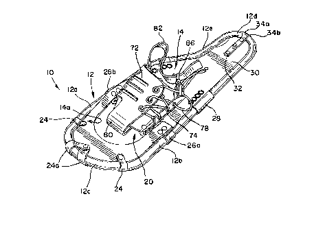
9 embodiment of the present invention as indicated generally at 10.
Briefly, the snowshoe 10 includes perimeter frame means 12 to
11 which is affixed floatation means 14 that extends substantially
12 the full longitudinal length of the frame means. The floatation
13 means 14 facilitates support of the snowshoe on powder snow, as
14 is known. Hinge rod means in the form of a hinge rod 16 (FIG.
3) has its opposite ends secured to the frame means 12 so as to
16 extend transversely of the frame means across an opening 14a in
17 the floatation means. The hinge rod 16 is positioned to underlie
18 the ball of a user's foot when the snowshoe is attached to the
19 user's shoe or the like. As will be described, the hinge rod 16
pivotally supports a foot plate means which includes a foot plate
21 18, alternatively termed a claw plate or binding support plate,
22 in a manner to enable pivotable movement of the foot plate
23 between a position generally coplanar with the frame means 12 and
24 an upward pivotable position forming an included angle of
approximately 45° with the plane of the adjacent frame means.
26~ The foot plate or binding support plate 18 supports
27 binding means, indicated generally at 20, which is affixed to an
28 upper generally planar surface of the foot plate and facilitates
29 attachment of the snowshoe to a user's shoe or the like, as
illustrated in FIG. 8. The snowshoe 10 illustrated in FIGS. 1
31 and 2 comprises one of a pair of snowshoes which are virtual
32 mirror images of each other, the snowshoe 10 being intended to
33 be worn on the user's left foot.
34 Turning now to a more detailed description of the
snowshoe 10, the frame means 12 is preferably made of a suitable
36 strength, non-corrosive, lightweight tubular metallic material,
~~.4~'~~9
_g_
1 such as aluminum. If desired, the frame means 12 may also be
2 made from other materials such as wood or suitable strength
3 plastic. The frame means 12 forms a closed loop having inner and
4 outer coplanar side rail portions 12a and 12b, respectively,
which establish a lateral width of approximately 8 inches for the
6 snowshoe 10. The side rail portions 12a and 12b terminate at
7 their forward ends in a forward rounded end frame portion 12c.
8 The end portion 12c is inclined upwardly relative to the plane
9 of the side rails at an angle of inclination of approximately 45°
so as to increase upward floatation in powder snow. The side
11 rail frame portions 12a and 12b terminate at their rearward ends
12 in a rounded tail end frame portion 12d so as to establish a
13 longitudinal length of approximately 25 inches for the snowshoe,
14 although other length snowshoes may also be desired. The inner
rail 12a is curved inwardly at 12e to provide a reduced width
16 tail end, termed a short step or runner cutout, which is
17 particularly desirable to reduce contact between snowshoes when
18 jogging or running.
19 In the illustrated embodiment, the floatation means 14
comprises a suitable snow and water impermeable sheet material
21 which preferably is relatively lightweight but has sufficient
22 tear and shear resistance for its intended purpose. The
23 floatation means 14 is particularly adapted for backcountry
24 snowshoeing in powder snow but also finds application on running
snowshoes because of its light weight. The floatation means 14
26 may be formed from 1000 denier nylon coated on its bottom surface
27 with an abrasion resistant polyurethane. The top surface of the
28 floatation means is generally not exposed to abrasive snow or
29 other ground materials and may be coated with a suitable plastic
material, such PVC. Other suitable strength materials could also
31 be used to form the floatation means 14, including traditional
32 webbing laced tightly to the frame 12.
33 The floatation sheet material includes a forward
34 portion 14b which partially defines the opening 14a and is
secured to the forward curved end 12c of the frame means 12 by
36 lacing, or alternatively with a plurality of loops 24 as
37 illustrated in FIGS. 1 and 2. The loops 24 are preferably formed
~~4~'~~9
-10-
1 integral with the floatation sheeting material and secured around
2 the frame with suitable fasteners, such as rivets or the like.
3 A pair of forwardmost loops 24a are looped about the frame and
4 angled back upon the floatation sheet material in overlapping
relation to each other where they are secured with a common rivet
6 or fastener to the floatation material so as to prevent lateral
7 movement of the floatation sheet material. The trailing ends of
8 the forward floatation sheet portion 14b are secured to hinge rod
9 straps 26a and 26b, respectively, which loop about the lateral
side rails of the frame means 12.
11 A rearward portion 14c of the floatation sheet material
12 extends from the hinge rod straps 26a,b to the trailing end 12d
13 of the frame means. The floatation sheet portion 14c defines the
14 rearward edge of opening 14a and has a peripheral outer contour
substantially equal to the planar contour of the rearward portion
16 of the frame means. The floatation sheet material 14c overlies
17 and is secured to a broad transverse support strap 28 through a
18 plurality of suitable fasteners, such as rivets. The transverse
19 support strap 28 is made of a similar high strength coated nylon
material and provides lateral strength or reinforcement for the
21 frame as well as supporting the weight of the user beneath the
22 heel portion of the user's boot.
23 The trailing end of the floatation sheet 14c is secured
24 to the curved end portion 12d of the frame means through an
elongated strap 30 having a forward end fixed to the floatation
26 sheet material through a fastener 32. A rearward end of strap
27 30 is connected to a pair of connector straps 34a and 34b by a
28 fastener 36. The connector straps 34a and 34b are looped about
29 the curved frame end 12d in generally side-by-side relation and
have the ends secured in overlapping or superimposed relation to
31 each other and to the tail end of the strap 30 by the fastener
32 34. The looped connector straps 34a,b prevent lateral movement
33 of the strap 30.
34 As illustrated in FIGS. 2 and 6, the trailing end of
the floatation sheet material 14c is of sufficient length to
36 underlie the curved end 12d of the frame means so as to be
37 pressed against the frame and assist in supporting the snowshoe
~I 4 ~'~~g
-11-
1 on a snow surface. When the snowshoe is lifted from the snow
2 surface, the end of the floatation sheet 14c rearwardly from the
3 fastener 30 can drop downwardly by gravity to discharge any snow
4 which has accumulated on the snowshoe interiorly of the frame.
Snow on the tail end of the snowshoe will also drop between the
6 lateral edges of the floatation sheet and the side rail portions
7 of the frame 12.
8 The foot plate or binding support plate 18 is generally
9 trapeaoidal shaped in plane configuration and may be made of a
suitable strength corrosion resistant material such as aluminum
11 or stainless steel. The foot plate 18 has a generally planar
12 plate portion 18a the upper surface of which supports the binding
13 means 20 as will be described. A forward transverse edge of the
14 planar plate portion 18a preferably has a downwardly directed
right-angle wall 18b having a toothed or serrated lower edge
16 which defines a plurality of cleats or talks that extend below
17 the lower plane of the frame means 12 when the foot plate is
18 generally coplanar with the side rails of the snowshoe frame
19 means. Laterally opposite rearwardly converging marginal edges
of the planar plate portion 18a of the foot plate are also
21 preferably similarly formed with downwardly directed right-angle
22 walls 18c and 18d which also have serrated lower edges forming
23 cleats or talks that extend below the frame means when the foot
24 plate is generally coplanar with the side rails. The cleats or
talks are preferably provided on the foot plate to provide
26 improved traction when traversing hard packed snow. If desired,
27 a rear claw, indicated at 40 in FIG. 3, may be secured to the
28 lower surface of the transverse support web 28 and has similar
29 downwardly projecting cleats or talks to prevent the trailing end
of the snowshoe from sliding laterally on hard packed snow or
31 when traversing inclined slopes. The lower exposed surface of
32 the foot plate 18 is preferably covered with a sheet 42 of
33 flexible coated nylon to inhibit adherence of snow to the foot
34 plate.
The foot plate means also includes retainer plate means
36 in the form of a retainer plate 44 which, as illustrated in FIG.
37 5, is secured to the lower surface of the planar portion 18a of
2~4~'~~9
-12-
1 the foot plate 18. The retainer plate 44 includes a planar plate
2 portion 44a and a U-shaped portion 44b. The planar portion 44a
3 is releasably secured to its lower surface by fastener means in
4 the form of a plurality of screws and locknuts 46 which enable
selective loosening of the retainer plate 44 relative to the foot
6 plate. The retainer plate 44 is secured to the foot plate 18 so
7 that the U-shaped portion 44b extends transversely of the foot
8 plate. Both the foot plate 18 and retainer plate 44 have
9 transverse widths substantially equal to the length of the hinge
rod 16 between oblong looped ends 16a and 16b formed on opposite
11 ends of the hinge rod, as illustrated in FIG. 3.
12 As aforedescribed, the hinge rod 16 is secured to the
13 laterally opposite side rails 12a and 12b of the frame means 12
14 so as to extend transversely of the longitudinal axis of the
frame means at a position to substantially underlie the ball of
16 the user' s foot to which the snowshoe is attached. The hinge rod
17 16 is preferably attached to the side rails 12a and 12b by means
18 of the hinge rod straps 26a and 26b which are looped through the
19 corresponding looped ends of the hinge rod. The hinge rod straps
have substantially greater transverse width than thickness and
21 are preferably formed of a high strength woven nylon base fabric
22 having a coating of polyurethane on the opposite side surfaces,
23 and with a thicker bead of polyurethane along their perimeter
24 edges to resist wear. The straps are looped about their
respective frame side rails and the looped ends of the hinge rod
26 16 so that the hinge rod straps firmly secure the hinge rod to
27 the frame.
28 Prior to assembling the foot plate 18 and retainer
29 plate 44 onto the hinge rod 16, bearing sleeve means in the form
of a low friction bearing sleeve 50, which may be made of
31 polyethylene and alternatively termed a hinge rod bushing, is
32 assembled in coaxial relation about the longitudinal length of
33 the hinge rod. To facilitate assembly of the bearing sleeve or
34 rod bushing 50 over the hinge rod 16, the bearing bushing is
preferably slit along its longitudinal length, as indicated at
36 50a in FIG. 5. As will be described, one feature of the snowshoe
37 10 is the ability to readily change the bearing sleeve 50 so that
~~48'~~9
-13-
1 bearing sleeves of different wall thicknesses may be utilized to
2 vary the resistance to rotational or pivotal movement of the foot
3 plate about the longitudinal axis of the hinge rod.
4 Referring again to FIG. 5, in assembling the foot plate
18 onto the hinge rod 16, the retainer plate 44 is placed about
6 the hinge rod and bearing sleeve so that they are received within
7 the U-shaped portion 44b of the retainer plate. The retainer
8 plate 44 is then secured to the foot plate through the screws 46
9 and associated locknuts. The U-shaped portion 44b has a fixed
nominal radius of curvature and has a free marginal edge 44b
11 which extends parallel to the axis of curvature of the U-shaped
12 portion 44b and is spaced from the lower surface of the planar
13 portion 18a of the foot plate in parallel relation thereto.
14 In accordance with one feature of the snowshoe 10, the
hinge rod 16, bearing sleeve or rod bushing 50, and retainer
16 plate 44 define shock absorber element means which can be
17 independently varied to vary the frictional resistance to pivotal
18 movement of the foot plate about the axis of the hinge rod.
19 These independent shock absorber elements cooperate with the foot
plate 18 to enable relatively free initial upward pivotal
21 movement of the foot plate about the hinge rod but substantially
22 dampens any tendency of the snowshoe to rapidly pivot about the
23 hinge rod 16 when the snowshoe is lifted off the snow surface as
24 in jogging or running on snowshoes. The cooperative shock
absorber means prevents or inhibits the forward end of the
26 snowshoe from engaging the user' s ankle or shin and also prevents
27 the tail end of the snowshoe from slapping against the heel of
28 the user's boot. As will be described, the cooperative shock
29 absorber means also stabilizes the snowshoe relative to the
user's foot so as to~enable backstepping when an obstacle is
31 encountered, as in backcountry snowshoeing.
32 In the illustrated embodiment, the length of the hinge
33 rod l6 between its oblong looped ends 16a and 16b is formed with
34 a non-circular cross section so as to define at least one, and
preferably a pair of cam surfaces 52a and 52b which effect
36 progressively increasing frictional resistance to pivotal
37 movement of the foot plate 18 relative to the frame means 12 as
~1~~'~J~
-14-
1 the tail end of the foot plate pivots upwardly about the hinge
2 rod. In the illustrated embodiment, the cam surfaces 52a and 52b
3 are formed as diametrically opposed outwardly facing arcuate
4 segments of a cylinder the axis of which coincides with the
longitudinal axis of the hinge rod. The arcuate cam surfaces 52a
6 and 52b are interconnected by laterally opposite generally planar
7 surfaces 54a and 54b which are equally spaced from the
8 longitudinal axis of the hinge rod and may be defined as chord
9 surfaces on the hinge rod.
The cam surfaces 52a,b and planar surfaces 54a,b are
11 formed on the hinge rod so that the planar surfaces 54a,b
12 normally lie in parallel planes forming included angles of
13 approximately 45° with the plane of the side frame rails 12a and
14 12b, as illustrated in FIG. 5. The diametrical distance between
the cam surfaces 52a and 52b, coupled with the wall thickness of
16 the bearing sleeve or rod bushing 50, the radius of curvature of
17 the U-shaped portion 44b of the retaining plate 44, and the
18 distance between the center axis of U-shaped portion 44b and the
19 foot plate planar portion 18a establish a geometrical relation
enabling relatively free upward pivotal movement of the trailing
21 end of the foot plate about the hinge rod during initial upward
22 pivotal movement from its lowered position generally coplanar
23 with the side rails 12a and 12b of the frame means. As the foot
24 plate approaches an upward pivotal position defining an included
angle of approximately 45° with the plane of the frame side rails
26 12a and 12b, relative rotation between the retaining plate 44 and
27 the hinge rod 16 causes the cam surfaces 52a and 52b to effect
28 increased frictional resistance to upward rotation or pivotal
29 movement of the foot plate about the hinge rod. By controlling
the wall thickness of the bearing sleeve or rod bushing 50, the
31 frictional resistance to relative pivotal movement between the
32 foot plate and the hinge rod 16 can be varied. When employing
33 a hinge rod having cam surface means, such as the cam surfaces
34 52a and 52b, the frictional resistance to relative rotation
between the foot plate and hinge rod can be varied to provide
36 progressively increased frictional resistance as the foot plate
37 approaches a pivotal angle of approximately 45° relative to the
~,~",
-15-
1 frame of the snowshoe. In this condition, as the user raises the
2 snowshoe frame and floatation means from the surface of the snow,
3 which generally occurs when jogging or running on snowshoes, the
4 increased frictional resistance to rotation of the foot plate
relative to the frame means prevents the frame means from freely
6 rotating or flopping about the axis of the hinge rod with
7 possible engagement of the toe portion of the snowshoe against
8 the shin or ankle of the user. Similarly, this action prevents
9 snapping of the tail end of the snowshoe against the user's heel
and thus acts as a shock absorber to prevent annoying noise and
11 imparting of an impact force against the user's heel.
12 Conversely, as the snowshoe is moved forwardly with the
13 foot plate 18 in its upward pivotal position relative to the
14 frame means 12, and with the frame means and floatation means 14
raised from the surface of the snow, as in jogging or running,
16 resistance to downward pivotal movement of the foot plate and
17 user's foot relative to the frame decreases as the snowshoe is
18 lowered to again engage the surface of the snow. This is due to
19 the interaction of the hinge rod cam surfaces with the retainer
plate 44, bearing sleeve 50 and planar portion 18a of the foot
21 plate which tends to bias the hinge rod to its original position
22 wherein the foot plate is again generally parallel to the plane
23 of the frame side rails 12a and 12b. In this manner, resistance
24 to downward pivotal movement of the foot plate and user's foot
relative to the frame is reduced sufficiently that as the user's
26 foot approaches the snow surface, substantially full surface
27 engagement of the snowshoe with the snow surface is effected.
28 It will be appreciated that with the hinge rod 16
29 having a cross-sectional configuration as described, and with the
U-shaped portion 44b of the retaining plate 44 being fixed
31 relative to the foot plate 18, varying the wall thickness of the
32 bearing sleeve or rod bushing 50 will vary the frictional
33 relation between the hinge rod and the foot plate throughout the
34 full range of pivotal movement of the foot plate. Thus, use of
a relatively thin wall bearing sleeve or bushing will result in
36 relatively little resistance to pivotal movement of the foot
37 plate about the hinge rod. This condition is particularly
~~4$~59
-16-
1 desirable in backcountry powder snowshoeing wherein it is desired
2 that the tail end of the snowshoe remain on the snow surface so
3 that the user does not waste energy lifting snow which has
4 accumulated on top of the snowshoe. In jogging or running on
snowshoes, the user may wish to inhibit the freedom of pivotal
6 movement of the foot plate about the hinge rod so that the
7 snowshoe does not flop around or slap against the user's foot or
8 engage the user's shin or ankle. In this case, a thicker wall
9 bearing sleeve or bushing would be selected to increase the
frictional resistance to pivotal movement of the frame means
11 relative to the foot plate and user's boot when the snowshoe is
12 raised from the snow surface.
13 It will also be appreciated that the frictional
14 relation between the foot plate 18 and the hinge rod 16 may be
varied by loosening the screws and locknuts 36. This will vary
16 the gap or spacing between the center of curvature of the U-
17 shaped portion 44b of the retainer plate 44 relative to the lower
18 surface of the foot plate 18, thereby lessening the resistance
19 to rotation of the foot plate about the hinge rod. The specific
size of dimensions of the retainer plate can also be varied to
21 change the frictional resistance to relative rotation between the
22 foot plate and hinge rod. Increasing the radius of curvature of
23 the U-shaped portion 44b of the retainer plate will reduce or
24 increase frictional resistance to rotation of the foot plate
about the hinge rod.
26 The frictional resistance to pivotal movement of the
27 foot plate about the hinge rod 16 may also be varied by changing
28 the contour of one or both of the cam surfaces 52a and 52b. For
29 example, the cam surfaces may be contoured to provide
progressively increasing resistance to upward pivotal movement
31 of the foot plate about the hinge rod as the foot plate pivots
32 from its lower position to an upward pivotal angle of
33 approximately 45° relative to the frame of the snowshoe.
34 The frictional resistance to relative rotation between
the foot plate 18 and hinge rod 16 can also be varied when
36 employing a cylindrical hinge rod which does not have cam surface
37 means formed on it. In this case, a bearing sleeve 50 is
-17-
1 selected with a wall thickness that will provide the desired
2 frictional resistance to rotation of the foot plate about the
3 hinge rod. A thin wall bearing sleeve will provide less
4 frictional resistance than a thicker wall bearing sleeve, for a
given hinge rod diameter and given radius of curvature of the U-
6 shaped portion 44b of the retainer plate 44.
7 Bridle means in the form an elongated generally non-
8 extensible flexible member 60 is cooperative with the foot plate
9 18 and hinge rod 16 so as to limit upward pivotal movement of the
foot plate about the hinge rod. The flexible member 60
11 preferably comprises a relatively high strength corrosive
12 resistant metallic substance having eyelets 62a and 62b fixed to
13 its opposite ends. As illustrated in FIG. 4, the opposite ends
14 of the bridle cable 60 are fixed to the lower side of the foot
plate on opposite sides of the hinge rod 16 through a pair of the
16 screws and locknuts 46 with the bridle cable passing through the
17 corresponding oblong looped end 16a of the hinge rod as
18 illustrated. The bridle cable 60 has a length which enables the
19 foot plate 18 to pivot or rotate upwardly about the hinge rod
through a rotational angle of approximately 45° at which time the
21 bridle cable is placed in axial tension and cooperates with the
22 looped end 16a of the hinge rod to prevent further upward pivotal
23 rotation of the foot plate about the hinge rod. The bridle cable
24 60 is particularly desirable when the snowshoe is used in running
to insure that the tail of the snowshoe lifts off the snow
26 surface when the foot plate 18 and user's foot reach an upward
27 angle of approximately 45° relative to the snow surface.
28 As aforedescribed, the hinge rod straps 26a and 26b
29 cooperate with the looped ends 16a and 16b of the hinge rod 16
to generally maintain the hinge rod in fixed rotational relation
31 to the snowshoe frame means . However, when the foot plate 18 has
32 reached an upward angular position of approximately 45° relative
33 to the snowshoe frame, at which time the bridle cable 60 prevents
34 further upward pivotal movement of the foot plate about the hinge
rod, the hinge rod straps 26a and 26b undergo a twisting action.
36 The hinge rod straps resist such twisting action and thereby
37 serve as a further shock absorber element in resisting upward
2~.4~°~~~
-18-
1 movement of the foot plate relative to the frame means. This
2 action further enhances the shock absorber characteristics of the
3 snowshoe.
4 By creating increased resistance to pivotal movement
of the foot plate about the hinge rod when the foot plate has
6 reached an upward pivotal angle of approximately 45° relative to
7 the snowshoe frame, a snowshoer can readily raise the snowshoe
8 from the snow surface with the frame and floatation means
9 remaining in relatively fixed relation to the user's foot. This
permits backward movement or stepping without the tail end of the
11 snowshoe frame dropping into the snow and inhibiting
12 backstepping. This is particularly desirable when the snowshoer
13 is confronted with an obstacle such as a fallen tree or the like,
14 termed a deadfall, which is covered by loosely packed snow so
that the snowshoer could drop downwardly into a pocket or void
16 in the powder snow. Upon approaching such an obstacle, the
17 snowshoer should immediately change direction as by backstepping.
18 ~ Referring to FIG. 7, the binding means 20 is preferably
19 made of a sheet material similar to the sheet material from which
the floatation means 14 is made so as to be impervious to snow
21 and water while providing sufficient strength and resistance to
22 abrasion. The binding means 20 may be formed from a single
23 pattern of sheet material so as to define a central panel portion
24 70 which is secured to the upper surface of the planar portion
18a of the foot plate 18, as through rivets or the like, and the
26 screws 46. A pair of laterally opposite generally longitudinally
27 extending wing panels 72 and 74 are preferably formed integral
28 with the central panel portion 70 of the binding and are of
29 sufficient length to cooperatively wrap around the forward
portion of a boot or the like such as indicated at 76 in FIG. 8.
31 A plurality of eyelets are formed in the outer marginal regions
32 of the wing panels 72 and 74 to receive a draw string 78 for
33 securing of the wing panels tightly about the boot.
34 A forwardly extending elongated tongue or toe piece 80
is preferably formed integral with the upper region of the wing
36 panel 72 and has a forward end portion 80a which is slidable
37 through a transverse slot 70a in the forward end of the central
-19-
1 panel 70 so as to overlie the central panel. The end 80a of the
2 toe piece 80 is curved laterally at 80b to extend to the lateral
3 margin of the central panel portion 70 and is connected to one
4 end of a heel strap 82 which passes through a loop 84 formed
through the lower region of the wing panel 72. In operation,
6 with the toe portion of the boot 76 positioned with its sole
7 above the central panel 70 of the binding means 20, the heel
8 strap 82 is pulled rearwardly to snugly engage the toe piece 80
9 with the toe of the boot and the heel strap is secured about the
heel portion of the boot by a suitable buckle 86. The wing
11 panels 72 and 74 are then secured about the boot by the
12 drawstring 78. In this manner, the boot is firmly retained
13 longitudinally and laterally within the binding means 20. The
14 longitudinal attachment means combines two components, the heel
strap and the toe piece into one adjustment strap thereby
16 simplifying attachment.
17 Having thus described a preferred embodiment of a
18 snowshoe in accordance with the present invention, it will be
19 appreciated that the snowshoe may be readily adapted for use in
backcountry powder snow through the provision of a relatively
21 thin wall bearing sleeve or hinge rod bushing 50 so as to enable
22 relatively free pivotal relation between the foot plate 18 and
23 the snowshoe frame, thereby enabling articulation of the user's
24 foot and leg without appreciable lifting of the snowshoe. Should
lifting of the snowshoe occur while traversing powder snow, the
26 powder which accumulates on the tail end~of the snowshoe may be
27 readily discharged between the marginal edges of the floatation
28 sheet material and the rearward portion of the perimeter frame,
29 with the rearward portion of the floatation sheet material
rearwardly from the strap fastener 32 opening downwardly to
31 provide ready discharge of snow.
32 By arranging the interconnection of the foot plate 18
33 to the hinge rod 16 to provide controlled frictional resistance
34 to relative rotation between the foot plate and hinge rod as
described, rapid movement or slapping of the tail end of the
36 snowshoe against the user's heel can be significantly inhibited
37 or substantially prevented, and the toe portion of the snowshoe
I G1 V
-20-
1 prevented from engaging the ankle or shin of the user. This is
2 particularly desirable when jogging or running on the snowshoe.
3 Each of the elements of the shock absorber may be used
4 independently to provide resistance to rotation, or cooperatively
to accomplish the same purpose. The shock absorber
6 characteristics of the snowshoe can also be controlled to
7 stabilize the snowshoe frame relative to the foot plate and
8 user's leg so as to provide improved re-engagement of the
9 snowshoe with the snow surface at the conclusion of each forward
step or stride of the jogger or runner. Additionally, the bridle
11 strap 60 prevents the foot plate from pivoting upwardly beyond
12 an angle of approximately 45° relative to the snowshoe frame,
13 thereby facilitating lifting of the snowshoe and preventing the
14 toe portion of the snowshoe from engaging the ankle or shin of
the user while running flat out. Slapping of the tail end of the
16 snowshoe against the user's heel can be significantly inhibited
17 or substantially prevented. The binding toe piece 80 facilitates
18 firm longitudinal retention of the user's boot within the
19 binding, thus eliminating any looseness which could cause fatigue
during snowshoeing, and simplifies the attachment by adjusting
21 two binding components, the toe piece heel strap, through
22 adjustment of only the strap.
23 While a preferred embodiment of the snowshoe in
24 accordance with the present invention has been illustrated and
described, it will be obvious to those skilled in the art that
26 changes and modifications may be made therein without departing
27 from the invention in its broader aspects. Various features of
28 the invention are defined in the following claims.