Note: Descriptions are shown in the official language in which they were submitted.
21 98892
STEAM IRON WITH A VERTICAL STEAMING FEATURE
BACRGROUND OF THE lNV~;N-l'lON
This invention relates to electric steam
irons and in particular to an electric steam iron
including a feature which enables the iron to
steam when the iron is held upright or in the
vertical plane.
Standard steam irons are designed to cease
steaming when the iron is placed in a vertical
position on its heel rest to avoid continuous
steaming in the resting position. The iron is
frequently placed on its heel rest during pauses
in ironing so that garments can be repositioned or
that spray or starch may be applied thereto.
Continuous steaming when the iron is on its heel
rest wastes water in the reservoir. Some irons
heretofore known employ a mechanism to insure that
the valve communicating the water reservoir with
the steam chamber is closed when the iron is
placed on its heel rest.
Some irons employ a pressure feed system to
obtain vertical steaming. Typically a gravity
feed system cannot be used since the valve
.. 21 48892
communicating the water reservoir with the steam
chamber is positioned too far towards the front of
the iron for a vertical feed system to function.
Pressure feed systems are relatively costly and
difficult to assemble in the rather confined space
formed within the iron's water reservoir.
It is therefore an object of this invention
to include a vertical steaming feature in an
electric iron operable when the user desires to
steam a garment or other similar product
positioned in a vertical plane. The vertical
steaming feature is overridden when the iron is
placed on its heel rest to discontinue the
introduction of water into the steam chamber.
SUMMARY OF THE lNV~'l'lON
The foregoing object and other objects of the
invention are attained in an electric steam
iron including a soleplate, an electric heater
attached in heat transfer relation with the
soleplate and a source of electric power connected
to the heater for delivering electric power
thereto. The iron includes a housing forming a
reservoir. Means forms a dam in the reservoir. A
steam generating chamber is in heat transfer
relation with the electric heater. Valve means
~ - 2l~8892
communicates the water reservoir with the steam
generating chamber for controlling the flow of
water from the water reservoir into the chamber.
The valve means is positioned within the water
reservoir relatively rearwardly of the dam means
so that a head of water is formed above the valve
means when the iron is placed upright with the
heel rest in a relatively horizontal plane and the
soleplate in a relatively vertical plane.
BRIEF DESCRIPTION OF THE DRAWING
Figure 1 is an exploded perspective view
illustrating the iron, the water cassette, and the
base for the iron and cassette;
Figure lA is an exploded perspective view of
the cassette and portion of the base illustrating
further details thereof;
Figure 2 is a side elevational view,
partially in section, of the iron being placed on
the base;
Figure 3 is a view similar to Figure 2 with
the iron on the base;
21~8892
-
Figure 4 is a side elevational view of the
iron, with parts broken away for clarity,
illustrating the iron on the soleplate thereof;
Figure 5 is a view similar to Figure 4 with
the iron on its heel rest;
Figure 6 is a view similar to Figures 4 and
5 with the iron in the base;
Figure 7 is a side elevational view of the
iron, partially in section, with the iron on the
soleplate;
Figure 8 is an enlarged sectional view of
the steam control assembly employed in the iron;
Figure 9 is an exploded perspective view of
the steam control assembly;
Figure 10 is a side elevational view with
parts broken away to illustrate a thermostat
control used in the iron;
Figure 11 is a top plan view of the iron
2I ~ 8892
-
further illustrating the thermostat control;
Figure 12 is an enlarged sectional view of a
portion of the iron illustrating the thermostat
control;
Figure 13 is a side perspective view of the
iron with parts broken away to illustrate a spray
nozzle assembly employed on the iron;
Figure 14 is an enlarged perspective view of
the spray nozzle assembly;
Figure 15 is an enlarged perspective view of
the nozzle assembly;
Figure 16 is a side perspective view of the
iron with parts broken away to illustrate a
reservoir fill control for the iron;
Figure 17 is a partial sectional view of the
iron illustrated in Figure 16;
Figure 18 is an exploded perspective view of
the iron and base illustrating details of the
2198892
-
water reservoir of the iron; and
Figure 19 is a plan view partially in
section and partially broken away of the water
reservoir.
DESCRIPTION OF THE PREFERRED EMBODIMENT
Referring now to the various figures of the
drawing, a preferred embodiment of the present
invention shall now be described in detail. In
referring to the various figures of the drawing,
like numerals shall refer to like parts.
Referrin~ specifically to Figures 1, lA, 2
and 3, there is shown an iron assembly 10
embodying the present invention. Iron assembly 10
includes an iron 11, a water cassette 16, and a
base 14. Base 14 includes a generally planar
platform member 15 terminating in a downwardly
inclined portion 41 at its rear end. Base 14
includes an upwardly extending rim 17. Platform
15 includes three standoffs 18 formed from
nonabrasive material such as rubber or the like.
Standoffs 18 contact the bottom surface of
soleplate 54 of the iron when the iron is placed
on the base. As standoffs 18 are made from
nonabrasive material, the standoffs will not
scratch the surface of the soleplate. Further,
2148892
the standoffs are made from high temperature
resistant material so that the iron may be placed
directly in base 14 immediately after ironing is
discontinued.
Base 14 includes a pair of inwardly extending
hook-like projections 20 formed at the top of rim
17 and located at the front of platform 15.
Hook-like projections 20 extend into a groove 55
formed between the top of soleplate 54 and the
bottom of skirt 58 of the iron when iron 11 is
placed on the base. A rectangular slot 2 6 and a
generally circular opening 28 are formed in
platform 15 to enable base 14 to be placed on a
mounting bracket for enabling iron assembly 10 to
be stored on a wall or similar surface when iron
11 is not in use.
Base 14 further includes a pivotal latch 22
having a hook-like portion 27 at one end and an
elongated finger 25 extending from hook-like
portion 27. The latch is preferably L or reverse
J shaped. A handle 23 is connected to latch 2 2 to
pivot the latch between locking and unlocking
positions. As shown in Figures 2 and 3, latch 22
further includes a spring 24 which keeps the latch
in its iron engaged position when the iron is
placed on base 14. As illustrated in Figure 3, a
somewhat rectangular slot 29 is formed at the rear
21 ~ 8892
face of the iron between soleplate 54 and skirt
58. Hook-like portion 27 projects within slot 29
to retain iron 11 on base 14.
When the iron is not located on the base, for
example when the iron is being used, finger 25
extends upwardly above the surface of platform
15. As iron 11 is moved towards the base, as
shown in Figure 2, finger 25 extends into the path
of movement of the iron. When the iron is placed
on the base, the rear portion of soleplate 54
contacts finger 25. The force developed by
soleplate 54 engaging finger 25 rotates latch 22
counterclockwise into its locking position. When
the user desires to remove iron 11 from base 14,
the user rotates handle 23 clockwise to pivot
latch 22 clockwise to release the iron. Even if
engaging finger 25 is moved below the plane of
platform 15 when the iron is not in the base, when
the front of the iron is placed in the base so
that projections 20 are inserted into groove 55,
the rear face of skirt 58 will contact portion 27
and rotate the latch clockwise until finger 25
contacts 54 of iron 11. Further movement of the
iron into the base will result in the latch
pivoting counterclockwise into its locking
position.
As shown in Figures 1 and lA, base 14
21~8892
includes a rear section 34 defining the rear wall
of the base. Rear section 3 4 includes a
vertically extending inwardly projecting abutment
member 3 0 and a tail portion 32 extending upwardly
from the top face 33 of rear section 34. Tail
portion 3Z comprises a generally horizontal
extending floor member 35, a pair of inwardly
inclined sidewalls 37 and an inwardly inclined
front wall 39. The rear of tail section 32 is
open.
Water cassette 16 includes a bottom wall 36
having a generally rectangularly shaped slot 43
formed therein. Slot 43 is configured to
complement the shape of tail portion 32 so that
the tail portion may be slid within the slot to
join the cassette to the base. Slot 43 terminates
in a vertical wall 45 which mates with vertical
wall 39 of tail portion 32 when the tail portion
is inserted into the slot. Cassette 16 further
includes a plurality of horizontally extending
ribs 38 to give rigidity to the wall 49 of
cassette 16. The ribs also function as a cordwrap
for power cord 59 when the iron is stored. A cap
51 is threadably received on the spout (not shown)
of the cassette.
Housing 12 includes a nose portion 50.
2 1 ~ 8 8 9 2
--10--
Housing 12 is attached to skirt 58 which, in turn,
is attached to soleplate 54. Groove 55 is formed
between the top surface of soleplate 54 and the
bottom surface of skirt 58. Groove 55 enables the
user to readily iron garments having buttons and
also functions to receive projections 20 as
previously described. Skirt 58 is generally
L-shaped and comprises a horizontal leg 58A and a
substantially vertical leg 58B.
Spray nozzle 52 extends forwardly of nose
portion 50 of housing 12. Nose portion 50 further
includes fill opening 48. Housing 12 further
includes handle 40. Steam control valve 4 2
extends upwardly from handle 40. Handle 40
further includes spray pump control 44. Control 44
activates pump 44A (See Figure 17) .
An on/off switch 46 is positioned on the
saddle portion 47 of housing 12. An arcuate
opening 62 iS formed in saddle portion 47. The
arcuate opening forms a track for thermostat
control knob 60. Arcuate opening 62 is inclined
downwardly about 2 from its rear to its
forward faces. The inclination of the track
follows the general contour of saddle portion 47.
A rear cover 56 is attached to the outer
surface of vertical leg 58B of skirt 58. An
opening is formed between the outer surface of leg
2198892
. _
58B and the opposed surface of cover 56. A cord
bushing 57 extends outwardly through the opening.
Cord bushing 57 surrounds power cord 59. Power
cord 59 is connected to a source of electrical
power for delivering electrical power to the iron
for actuating among other components the
electrical resistance heater (shown in Figure 18)
associated with the soleplate in heat transfer
relation as is conventional in the art. A
rotatable foot-like member 70 is attached to cover
56 for a reason to be more fully explained
hereinafter.
Referring now in detail to Figures 4-9, the
function of foot member 70 in conjunction with the
steam control, on/off switch, and base shall be
more fully explained.
As illustrated, foot member 70 is pivotally
connected to cover 56 at pivot 72. As shown in
Figure 4, when the soleplate is placed in a
horizontal plane and the iron is supported on an
underlying garment or the surface of the ironing
board, foot member 70 lies generally parallel to
the soleplate and is spaced above the underlying
support surface. An actuator arm 102 of steam
control assembly 100 extends within the pivotal
path of movement of foot member 70. When
the iron is positioned as shown in Figure 4,
2148892
- -12-
actuator arm 102 is urged towards cover 56.
Further as illustrated in Figure 4, on/off
switch 46 is in its on position connecting iron 11
to the source of electrical power. On/off switch
46 is pivotally connected to skirt 58 via bracket
76. On/off switch 46 includes a trigger member
78. Rotatable actuator 80 is positioned in the
path of movement of foot member 70 when the iron
is placed on base 14 as illustrated in Figure 6.
Movement of actuator 80 results in contact between
the actuator and trigger member 78.
Figure 5 illustrates the iron supported on
its heel rest. The rear surface of cover 56
defines the heel rest for the iron. As the iron
is rotated from its horizontal position to its
heelrest position, the weight of the iron provides
a force to rotate foot member 70 in a
counterclockwise direction to achieve the position
illustrated in Figure 5. The weight of the iron
also provides a force which causes the
foot member to translate parallel to the soleplate
in the direction of the arrow shown in Figure 5.
When so translated in the direction shown, notch
81 of the foot member engages a complementary
surface 82 on the cover to latch the foot member
in the position illustrated. Spring 83 is
2148892
-13-
compressed as a consequence of the rotational
movement of foot member 70.
When foot member 70 has been rotated to the
position illustrated in Figure 5, the foot member
extends the effective length of the heel rest. It
should be noted that iron 11 has a rather unique
shape. Particularly, it should be noted that the
upwardly extending leg 58B of skirt 58 is at an
obtuse angle relative to horizontal leg 58A of the
skirt. Typically, the upwardly extending leg of a
skirt is perpendicular or at an acute angle to the
horizontally extending leg of the skirt. Thus,
the cover of the iron attached to the upwardly
extending leg readily provides a suitable support
for the iron when the iron is placed in the heel
rest position. Due to the rather unique shape of
the present iron 11, and in the absence of foot
member 70, the weight of the iron will cause the
iron to rotate in a counterclockwise direction if
the iron were placed on cover 56. Foot member 70
when extended in the position shown in Figure 5,
increases the length of cover 56 so that the
fulcrum or pivot point for the iron is shifted to
the left (towards the soleplate) as viewed in
Figure 5 so that the clockwise moment arm tending
to maintain the iron on its heel rest increases
2148892
-14-
in magnitude and the counterclockwise moment arm
decreases in magnitude. A relatively light weight
86 may be added to the handle to increase the
magnitude of the clockwise moment arm to further
insure the stability of the iron when the iron is
placed on its heel rest. Since the fulcrum has
been moved as a consequence of the extension of
foot member 70, weight 86 may be relatively light
so as not to unduly increase the total weight of
the iron.
As illustrated in Figure 5, the rotational
movement of foot member 70 results in leg 70A
thereof contacting actuator arm 102 of steam valve
assembly 100. The force provided by leg 70A moving
into contact with actuator arm 102 of steam valve
100 moves the actuator to the left as viewed in
Figure 4 or upwardly as viewed in Figure 5. As
shall be more fully explained hereinafter, this
movement of the actuator arm results in the
stoppage of flow of water from water reservoir 120
into steam chamber 122.
When iron 11 is moved from the heel rest
position illustrated in Figure 5 to the ironing
position illustrated in Figure 4, notch 81
21~8892
-15-
disengages from surface 82, enabling foot member
70 to rotate in a clockwise direction as viewed in
Figure 4. Spring 83 provides the force to rotate
foot member 70 from its heel rest position (Fig.5)
to the ironing position (Fig. 4). If the foot
member is jammed into its heel rest position when
the iron is returned to its ironing position, the
lower edge 70D of foot member 70 extends below the
bottom surface of soleplate 54. Edge 70D contacts
the underlying support surface (ironing board or
garment) and the force of such engagement triggers
the foot member to translate in the direction
opposite to the arrow illustrated in Figure 5.
This movement releases notch 81 from surface 82.
Referring now to Figure 6, iron 11 is shown
mounted on base 14. When the iron is placed on
its base, abutment member 30 of rear section 34 of
the base engages foot member 70 to rotate foot
member 70 in a counterclockwise direction. As
noted previously, the foot member is rotated in a
counterclockwise direction when the iron is placed
on its heel rest; however the shape of abutment
member 30 causes the foot member to have a larger
arc of rotation when the iron is placed on base 14
than when the iron is placed on its heel rest.
21~8892
16
Foot member 70 is rotated counterclockwise
when iron 11 is placed on the base, to move
actuator arm 102 of steam valve assembly 100 to
the left as shown in Figure 6. Further, upper
face 70C of the foot member engages actuator 80
associated with on/off switch 46. The actuator in
turn engages trigger member 78 of the switch to
rotate the switch in a counterclockwise direction
from its on position to its off position. Thus,
when iron 11 is placed on base 14, engagement of
foot member 70 with abutment member 30 results in
the foot member moving the actuator arm 102 to
discontinue flow of water into steam chamber 122
and also results in the electrical power to the
iron being interrupted since the on/off switch is
moved into its off position. Inclined portion 41
of platform member 15 enables foot member to
rotate to the position shown in Figure 6 when the
iron is placed on base 14. Inclined portion 41
accepts the extended portion of foot member 70
terminating in edge 7OD.
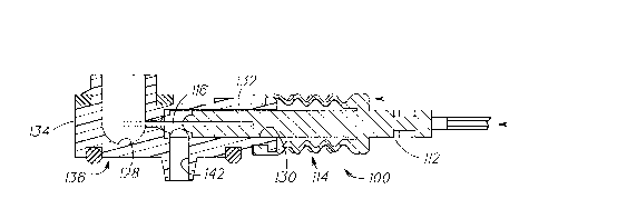
Referring now to Figures 7, 8, 9, and 18,
steam control assembly 100 shall now be described
in detail. Steam control assembly 100 is mounted
2148892
- --17--
in a track 124 formed in the top surface 126 of
skirt 58 and includes a longitudinally extending
actuator arm 102 which, has one end as previously
described extending into the path of travel of
foot member 7b. As shown in Figure 9, actuator
arm 102 is connected to a rib 106 which in turn is
connected to an actuator fork 108 having a
U-shaped slot 110 formed therein. One end 112 of
a spring bellows 114 extends within slot 110.
The other end of spring bellows 114
terminates in a longitudinally extending pin 116.
As shown in Figures 7 and 8, the pin and
associated end of the spring bellows extend into
an orifice 130 of conduit 132. Conduit 132
extends outwardly from the sidewall 134 of valve
housing 136. Valve housing 136 includes a chamber
128. Passageway 140 communicates orifice 130 with
chamber 128. Passageway 140 also communicates
chamber 128 with outlet 142. Pin 116 extends
through the passageway into the chamber to clean
the passageway and meter the flow of water from
the chamber into the passageway. End 112 of
bellows 114 closes the passageway when the bellows
is moved to the left as viewed in Figure 8 and
interrupts flow between chamber 128 and outlet
21~8892
- -18-
142. Actuator arm 102 moves bellows 114 to
terminate the flow of water from water reservoir
120 into steam chamber 122.
Housing 14 includes steam control valve 42
for enabling the user to operate iron 11 in either
dry or steam modes. Figure 7 illustrates control
valve 42 when the iron is being operated in its
steam mode. Steam control valve 42 is connected
via valve stem 144 to valve 146. As shown, when
valve 146 is spaced above chamber 128, water will
flow from water reservoir 120 into valve chamber
128 and thence into outlet 142 and steam chamber
122. When in the position shown, iron 11 may be
used to steam and iron a garment. If dry ironing
is desired, control valve 42 is moved downwardly
to move valve stem 144 and attached valve 146
downwardly to close off the flow of water from
reservoir 120 into chamber 122.
When the iron is rotated into its heel rest
position, foot member 70 is rotated in a
counterclockwise direction which, in turn, moves
actuator arm 102 to the left as viewed in Figures
7 and 8. Movement of the actuator arm in this
manner results in end 112 of bellows 114 closing
the orifice to discontinue the flow of water from
- ~ . 2l~8892
- --19--
the water reservoir through chamber 128 and then
into outlet 142. The same movement
of the foot member and actuator arm occurs when
the iron is placed in the base and the foot member
engages abutment member 30.
Referring now to Figures 10-12, there is
disclosed a preferred embodiment of the thermostat
control for iron 11. As noted previously, saddle
47 of the iron includes an arcuate track 62 in
which control knob 60 is movably mounted. Track
62 extends arcuately in a horizontal plane through
the saddle portion and, as shown in Figure 12 has
a vertical slope so that track 62 is angled
downwardly from the rear end of iron 11 towards
nose portion 50 thereof. The slope of the track
is substantially 2 and the arcuate travel of knob
60 in track 62 is substantially 10.
As shown in Figure 12, control knob 60 is
connected to a vertically extending pin 150. The
vertical axis of pin 150 is offset inwardly
towards the center of iron 11 with respect to a
vertical plane passing through the center of knob
60. Pin 150 extends within horizontally extending
slot 152 of actuator lever 154. Lever 154 is
integrally formed with rotatable actuator 156.
21~8892
_
-20-
Actuator 156 is attached to upwardly extending
shaft 149 of thermostat 148. Thermostat 148
senses the temperature of soleplate 54. Pin 150
and actuator lever 154 comprise a linkage
connecting control knob 60 to actuator 156, which
in turn controls the operation of thermostat 148.
The length of the radius establishing arcuate
track 62 is substantially larger when compared to
the length of the radius establishing the
rotational path of movement of actuator 156.
Movement of control knob 60 through a 10 arcuate
path of travel results in substantially a 120
rotational movement of actuator 156 and shaft 149
of thermostat 148.
As shown in Figure 11, as control knob 60 is
arcuately moved along track 62, pin 150 transfers
the force developed by movement of the knob to the
actuator lever 154 and then to actuator 156 for
establishing a set or operating point for
thermostat 148. As the arcuate path for travel of
knob 60 is substantially less than the arcuate
path of travel of actuator 156, the distance
between pin 150 and the center of rotation of
actuator 156 is constantly changing. Further, the
vertical position of the pin relative to slot 152
-- 2148892
-21-
changes during movement of knob 60 due to the
inclination of track 62. Pin 150 slides within
slot 152 of lever 154 as a consequence of the
movement of the control knob. In effect, the slot
compensates for the vertical movement of pin 150
relative to lever 154 and also enables the
distance between pin 150 and the center of
rotation of actuator 156 to change. The described
control enables thermostat control knob 60 to be
mounted on a saddle having a rather complex
geometrical shape.
Referring now to Figures 13-15, there is
disclosed a preferred embodiment of the spray
nozzle assembly 52 as used in the present iron
assembly 10. Spray nozzle assembly 52 is mounted
at the nose portion 50 of iron 11. Spray pump
control 44 extends upwardly from handle 40 of iron
11. When the user desires to spray an underlying
garment, the user presses downwardly on pump
control 44 which creates a pumping action to pump
water via pump 44A (See Figure 17) from water
reservoir 120 through line 182 and then through
nozzle 52A of nozzle assembly 52. Nozzle assembly
52 includes nozzle 52A having a generally
frusto-conically shaped outer wall 162 and an end
21~8892
-
-22-
wall 164 having a spray opening 166 generally
located at the center thereof. Outer wall 162
defines a longitudinally extending bore 168. A
spreader element 170 is disposed within the bore
for reciprocating movement therein.
Spreader element 170 includes a generally enlarged
cylindrical head 172, a longitudinally extending
body portion 174 and a spherical spreader end 176.
A coupling 178 extends within an open end 180 of
nozzle assembly 52. Line 182 is fitted over the
outer end of coupling 178 to communicate bore 184
with water reservoir 120. Coupling 178 includes a
valve seat 188 facing towards spherical end 176 of
spreader element 170.
In operation, when the user desires to spray
a garment being ironed, the user pumps control 44
to pump water from water reservoir 120 via pump
44A through line 182, thence into bore 168. The
force of the water moves the spreader to the left
as viewed in Figure 14 so that surface 190 of the
spreader contacts the inwardly extending pads 192
of nozzle assembly 52. Cylindrical head 172 of
spreader element 170 directs the water in bore 168
towards the perimeter. Raised pads 192 comprise a
plurality of circumferentially spaced members
`_ 21~8892
-23-
disposed on the interior surface of end wall 164.
The water forced to the perimeter of bore 168
flows under the spreader and then radially
inwardly between the raised pads to the centrally
located orifice 166. The water is then sprayed in
a desired pattern onto the garment.
When the user ceases pumping control 44, the
return action of pump 44A creates a suction on
line 182 moving spreader element 170 to the right
as shown in Figure 14 which results in spherical
end 176 engaging seat 188 to create a seal. The
seal prevents air from being sucked into the
discharge side of pump 44A..
Referring now to Figures 16 and 17, the
details of the fill system for water reservoir 120
shall be described in detail. A somewhat
elliptically shaped opening 48 is formed in
housing 12 at the nose portion or front end
thereof 50. Opening 48 communicates with a water
flow passage 194 defined between downwardly
extending ribs 196. Ball valve or float valve 198
is disposed within flow passage 194. The specific
gravity of ball valve 198 is less than one so that
the valve floats on water. Lower wall 208 of
reservoir 120 and the ribs entrap the ball valve.
- 21~8892
-24-
When the ball valve is moved upwardly within the
passage, the ball valve seats against valve seat
202 to prevent water from splashing outwardly
through opening 48.
When the user is filling water reservoir 120,
a source of water is placed in communication with
flow opening 48. For example, flow opening 48 may
be placed beneath a faucet or cassette 16 may be
used to add water to reservoir 120. Water fills
the water reservoir causing float valve 198 to
move upwardly in passage 194. When the iron is in
normal use and water is in the reservoir, the
float valve again is moved upwardly since its
specific gravity is less than one. Valve 198 is
forced against seat 202 to prevent the water from
splashing outwardly through opening 48 during
normal ironing use.
Further, when the iron is placed in a
vertical position, for example when it is desired
to steam or iron a garment held in a vertical
position, if water level in the reservoir is
relatively high, the water will cause ball valve
198 to remain seated, preventing water from
splashing out when the iron is held upright.
Referring now to Figures 18 and 19, the
structure of reservoir 120 shall now be more fully
214 8892
-
-25-
described. Reservoir 120 includes a plurality of
walls 204 and 206 which extend upwardly part way
from the top of lower or bottom wall 208 of
reservoir 120. Walls 204 and 206 serve as dam
means or as weir means to separate the reservoir
into a forward compartment 210 and a rear
compartment 211. It should be noted opening 212
in bottom wall 208 is located at the rear of
forward compartment 210. In effect, walls 204
and 206 serve as dam means to provide a head of
water above opening 212 when the iron is held in a
vertical position. The head of water in forward
compartment 210 enables iron 11 to be used as a
steamer while the iron is held in a vertical
position. By trapping water in the forward
compartment when the iron is turned vertical,
water will continue to flow from reservoir 120,
through opening 212, steam valve chamber 128 and
then into steam chamber 122. The iron will
generate steam for a period of time until the
supply of trapped water in compartment 210 is
exhausted.
To replenish the supply of water in forward
compartment 210, the user need only tip the iron
forward and water in rear compartment 211 will
2148892
flow into the forward compartment. When the iron
is returned to its vertical position, divider
walls 204 and 206 will retain the water in the
forward compartment.
A water window 214 is disposed on saddle
portion 47 and in alignment with rear compartment
211. When the iron is placed on its heel rest or
held vertical, the user may look at the water
window which, since it is in vertical alignment
with the rear compartment provides an accurate
indicator of the amount of water remaining in the
water reservoir. If there is insufficient water in
the reservoir to satisfy the steaming function,
additional water can be added to reservoir 120
from cassette 16 or from a sink faucet.
While a preferred embodiment of the present
invention has been described and illustrated, the
invention should not be limited thereto but may be
otherwise embodied within the scope of the
following claims.