Language selection

Search

Patent 2149335 Summary

Third-party information liability

Some of the information on this Web page has been provided by external sources. The Government of Canada is not responsible for the accuracy, reliability or currency of the information supplied by external sources. Users wishing to rely upon this information should consult directly with the source of the information. Content provided by external sources is not subject to official languages, privacy and accessibility requirements.

Claims and Abstract availability

Any discrepancies in the text and image of the Claims and Abstract are due to differing posting times. Text of the Claims and Abstract are posted:

  • At the time the application is open to public inspection;
  • At the time of issue of the patent (grant).
(12) Patent Application: (11) CA 2149335
(54) English Title: A METHOD AND A PIPE ELEMENT FOR PROVIDING A RADIALLY OUTWARDS DIRECTED BEAD AT THE END RIM OF A PIPE
(54) French Title: METHODE ET ELEMENT DE TUYAU SERVANT A DOTER LE REBORD D'EXTREMITE D'UN TUYAU D'UN BOURRELET ORIENTE VERS L'EXTERIEUR DE FACON RADIALE
Status: Deemed Abandoned and Beyond the Period of Reinstatement - Pending Response to Notice of Disregarded Communication
Bibliographic Data
(51) International Patent Classification (IPC):
  • B21D 39/04 (2006.01)
  • F16L 13/14 (2006.01)
  • F16L 13/16 (2006.01)
(72) Inventors :
  • KRICHAU, PETER (Denmark)
  • ANDRESEN, WERNER J. (Denmark)
(73) Owners :
  • LINDAB A/S
(71) Applicants :
  • LINDAB A/S (Denmark)
(74) Agent: GOWLING WLG (CANADA) LLP
(74) Associate agent:
(45) Issued:
(86) PCT Filing Date: 1993-11-11
(87) Open to Public Inspection: 1994-06-09
Examination requested: 1999-12-06
Availability of licence: N/A
Dedicated to the Public: N/A
(25) Language of filing: English

Patent Cooperation Treaty (PCT): Yes
(86) PCT Filing Number: PCT/DK1993/000369
(87) International Publication Number: DK1993000369
(85) National Entry: 1995-05-12

(30) Application Priority Data:
Application No. Country/Territory Date
1393/92 (Denmark) 1992-11-20

Abstracts

English Abstract

2149335 9412295 PCTABS00032
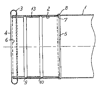
In this method a short pipe element (2) with a radially outwards
directed bead (3) at its end rim (4) is inserted into a pipe, and
a radially outwards directed bead (7, 8) is rolled in the other
end (5) of the pipe element (2) and in the pipe (1), such that
the pipe element is fixed inside the pipe. The pipe element (2) may
before insertion into the pipe be provided with at least two
radially outwards directed beads (9, 10), causing the pipe element
after insertion to be tightly clamped and fixed inside the pipe,
and the pipe element (2) may over a part of its outer surface be
coated with a sealing material (13).


Claims

Note: Claims are shown in the official language in which they were submitted.

PCT/DK93/00369
CLAIMS
1. A method of providing a radially outwardly directed
bead at the end rim of a pipe (1) made of thin plate,
comprising the steps of inserting a short pipe element (2)
with a radially outwardly directed bead (3) at one end rim
(4) into the pipe (1), and rolling a radially outwardly
directly bead (7, 8) in the pipe element (2) at its other
end (5) and in the pipe (1), thereby firmly fixing the
pipe element (2) inside the pipe (1), c h a r a c t e -
r i s e d in that the pipe element (2) is provided with at
least two radially outwardly directed beads (9, 10) before
insertion into the pipe (1), said beads (9, 10) causing,
after the insertion, the pipe element to be firmly clamped
and fixed inside the pipe.
2. A method according to claim 1, wherein the pipe
element (2) after insertion is spot welded to the pipe
(1).
3. A method according to claim 1 or 2, wherein
radially outwardly directed embossments (12) are embossed
in the pipe element (2) and the pipe (1) after the inser-
tion of the pipe element (2).
4. A method according to any one of the preceding
claims, wherein the pipe element (2) over a part of its
outer surface is coated with a sealing material (13).
5. A method according to claim 4, wherein the sealing
material is an elastic material (13), preferably rubber or
teflon.
6. A method according to claim 4, wherein the sealing
material is a mastic (13).
7. A method according to any one of the preceding
claims, wherein an adhesive is applied to a part of the
outer surface of the pipe element (2).
8. A pipe element for use in performing the method
according to claim 1 and having a radially outwardly
directed bead (3) at one end rim, c h a r a c t e -

PCT/DK93/00369
r i s e d in that it has at least two separate radially
outwardly directed beads (9, 10).
9. A pipe element according to claim 8, wherein a
part of its outer surface is coated with a sealing mate-
rial (13).
10. A pipe element according to claim 9, wherein the
sealing material is an elastic material (13), preferably
rubber or teflon.
11. A pipe element according to claim 9, wherein the
sealing material is a mastic (13).
12. A pipe element according to any one of the pre-
ceding claims 8-11, wherein an adhesive is applied to a
part of its outer surface.
13. A pipe element according to any one of the pre-
ceding claims 8-12, wherein it is made of steel, alumi-
nium, or plastic.

Description

Note: Descriptions are shown in the official language in which they were submitted.


t ~094/12~95 ~ ` .i-. PCT~K93100369
~; 2 ~ g~ 9 3 3 S
A method and ~a pipe element~for providing~a radially
outwards direoted bead at the~end rim of a~pipe.
The:inventlon relates to a method:of;provlding a ~ .
- radially outwards~directed;bead~at~the end rim:of a pipe : .
5 made:from thln plate. The invention furthermore relates~
to~a plpe element; to~be ~use~when~implementing :the. `:
: method.
: ~ : It is known~:to provide~pipes made from~thin plate
for instance~spirally~ wound~pipes`-~:with~ beads or~
: lO: simi;lar flanges~at;~thèir~end~rims, which allow two pipes~
to be connected~tightly to each other by means of clamps ~ : :
or similar devices engaging the` adjacent beads at the
~ ~ end rims~and pulling~them against~each other or against
;~ corresponding~seal:ing~surfaoes of~the~clamping device.
lS The monufacture~of~beads a~t~;the~end~rim~of a pipe~is~
performed by flanging~the~ends~o~ the~pipes~in powerful :
~ : special machines:at a~ factory.~It~:has~therefore not ; :
`~ unti:l now been:possible at:a~later:point~in:time to add~
bead.s~at the:end~rims~;of:pipes whic~ hàve~been shortened
: 20 whioh;is a signif:icant:~drawback.
The object of:the~.present~invention is ta provide
:a~method of~pro~idin~g:a bead at the~end:rim of a pipe~
:; made from thin: plate,: thus:i:avoiding the drawback
;mentioned~above..
:25 :: This is~ according to the:::invention achieved by:a
~ method~:of the typè:~mentioned ~above~,~characterized by~
.i~ inserting a~short pipe element:~with a radially outwards~
:~ directed bead: at :one: end: rim into:the:pipe, and by~
rolling~a~rad~a~ly:outwards~directed~:bead~in the plpe~
30~;element~::at:its~other e*d and~in~the;~ip pe:,~thereby;~fi
.~ :;fixing~the~pipe~e~ement inside~th :~:pipe:.
`r"~ Y~ ~ i izi ~ ready-mad ~ s rt~pipe~ elements
provided¦~with a-~bead~at~the~rim:oP~:one~e ~,~;it is only~
; necess:a ~ at-~;`:the~ build ng~ site~ to~ insert the~: pipe~

~ wo 94/12295 l` 21~ 9 3 3 5 PCT~K93/00369 ~,'`
,s~ i; ,1 ~ .
2 '
elemient into a shortened;pipe, ln order to subsequently
roll a bead at the end of the pipe element positioned ¦
inside the pipe by means of a convent~ional beading
machlne, Thus a bead in the~pipe wall ls also produced,
5 and the engagement of the two overlapping beads causes
the pipe element to be flrmly fixed inside the~pipe.
This method has; the further advantage that thè~
, ~ described rolling of the bead produces ~a smooth~
;transition between~ the~ plpe and thé;~pipe element,~
lO thereby avoiding the generàtion of ~nolse ~or pressure
-~ loss during transportation of~materlaI through the pipe.
~ ccording to a preferred ~embodiment, the pipe
element may 'be proyided with at le'ast two radially
~j, outwards direated~beads be~ore lnsertion into the pipe,'~ , 15 where said beads after the insertion Gause the pipe
element to be flrmly Glamped and flxed inslde the pipe.
~;The beads~are made such that the~dlameter of the
; pipe element mea~sured~at the top of a~`~bead~s:ubstantially
corresponds to the inside~dlameter~of~ the plpe. This
,20 assures a tight-fit when the~pipe element~is inserted
into the pipe.;The~b~eads are placed such that they are~
separated by a`suitably large~dlstance, thereby allowing
the pipe element to be guided~coaxiàlly into the pipe.
; ~
,In further~embod~iments the~pipe~element may after
25 insertion be~spot ~welded to~ the ~pipe,~ or radlally~
` outwards directed embossments~may be embossed `lnto the~
pipe and the pipe element,~ thus~ achiev;ing a urther~
fixing of the pipe element inside the;~pipe.
In other embodiments~the pipe element may be coated~
. ~ -
30 by~a~sealing material~,~which may be~an~,elastic material,~
preferably~rubber or teflon,~or-the~se,a1lng~materlaI may~
be~a mastlc.
The~gealing material,may be~placed 1n~advance~on~ ;
,~the outside of~the~pipe element.~;~A rubber layer may for`~
~ 35 Inst~noe bo _ d~by bondl~ or vulaa~z~ Lon, or~th~

L
09411229S ~ 21~ 9 3 3~ PCT~K93/0030
'' ~,
3 ; ~ : ~
~ ` !
sealing material, for instance a mastic, may be sprayed
- an immediately~before the pipe element is joined to the ,
pipe. :~
A further embodiment is characterized in that an
5 adhesive is applied to a~ part~of the outer surface o~f
the pipe element.~Thus~a further strengthening of the
~oint between~the pipe element~and the pipe is achieved.
: The invention :also~ relates to a pipe element for
: ~ use in performlng~the~method described above, said pipe
lO element being charaoterlzed:in~that lt.~has a radially~
outwards directed~bead~at one~end rim~
: ~ Further:embodlments:of the~pipe~element according
; tolthe inve~tion are:stated in the claims 10-15.
The invention~will now be~exp1ained in more detail :~:
lS :by~means of~an ~embodiment~ and~:wlth~ reference to the
:~ drawing,;ln~which
Figure:~l shows:~a longitudinal:sectiona1~vlew of~a
pi~pe element~according~to the lnvention, where the~pipe : ~
element is undér~:insertion into~a~pipe, :: : :~:
ao :~ Flgure:2 a~longitudlnal sectldhal view as ln Figure
: : . 1, where:the:pipe~e1ement is:~fully inserted into the~
plpe:and~oined~to~sald pipe by~the~method according to
the invention,~and:~
.;:~ :Figure 3;a~partial sectlonal~view ln~a larger~scale :`
25~:showing: a radially~outwards dlrected embossment~ln a~
pipe ~olnt accord-~ng~:to:the:in~ention.
In Figure~l~of~the drawing;a;pipe ele~ènt: 1:made~
.. ~ from thin~plate~is shown:, ~where thè;;pipe element:for ~ i
: lnstànce may~be:~a~cut~off;sectlon~of~a:~length~of~plpe ~ :~
. ~ 30~orIglnally provldèd~wlth;~beads~at lts:~end~rlm, or lt~ y~
be:~a:part:~of`a~sta~ndard:~pipe fitt ~ ~:such~as~a~T-plece~
,r~ or~a~pipe:~bénd-~ The~:fig~re~further~shows~:~a~pipe~element~ :
` 2,:~;which~in thi:s~ase~;is~manufactured fram~`thin :-plate.
The~:p pe ele t~2 s a~bead~3~at~ e~end~rlm 4,~:~while~ ;
35~the~other~end S~of~ the~plpe element 2~hàs~been cut~off

W094/12295 2¦49~3s PCT~K93/00369 ~
with a straight cut. The pipe element 2 furthermore has
two radially outwards directed beads 9 and 10, which are
placed with a separation causing pipe element 2 to be
guided coaxially into the pipe l durin~ the insertion
5 of said pipe element 2~.
A rubber layer 11, which in this case ls bonded to
the pipe, is placed between:the beads 9 and 10. The
outer dimension of the sealing element is such that it
will be in contact with~the inner~wall of the pipe 1
lO after insertion into the pipe l,~thus sealing the gap~
between the pipe element 2 and the pipe l.
Figure 2 shows that beads 7 and 8 after insertion:
of the pipe element 2 ihto the pipe l.are rolled in the
pipe element 2 and the pipe 1, respectively, at the end
~ 15~rim of the pipe element 5. The rolling is in this case
; performed such~that the bead 7 in~ the pipe element 2
only ~s a "halfl-~bead, which assures a good locking o~
bead 7 in bead 8, while at the;same time providing:a
smooth transltion:between the inner surfaces of the pipe
`20 1 and the plpe element:2, respecti~ely.
~: Figure 3 shows~embossments 12 in the pipe element
: : 2 and the pipe l. The embossments are produced by means
;of known hand tools.
~; ~
s !:

Representative Drawing
A single figure which represents the drawing illustrating the invention.
Administrative Status

2024-08-01:As part of the Next Generation Patents (NGP) transition, the Canadian Patents Database (CPD) now contains a more detailed Event History, which replicates the Event Log of our new back-office solution.

Please note that "Inactive:" events refers to events no longer in use in our new back-office solution.

For a clearer understanding of the status of the application/patent presented on this page, the site Disclaimer , as well as the definitions for Patent , Event History , Maintenance Fee  and Payment History  should be consulted.

Event History

Description Date
Inactive: IPC from MCD 2006-03-11
Application Not Reinstated by Deadline 2004-11-12
Time Limit for Reversal Expired 2004-11-12
Deemed Abandoned - Conditions for Grant Determined Not Compliant 2004-02-19
Deemed Abandoned - Failure to Respond to Maintenance Fee Notice 2003-11-12
Notice of Allowance is Issued 2003-08-19
Letter Sent 2003-08-19
Notice of Allowance is Issued 2003-08-19
Inactive: Approved for allowance (AFA) 2003-08-07
Amendment Received - Voluntary Amendment 2003-06-18
Inactive: S.30(2) Rules - Examiner requisition 2003-01-27
Amendment Received - Voluntary Amendment 2000-04-04
Letter Sent 2000-02-01
Inactive: Application prosecuted on TS as of Log entry date 2000-01-31
Inactive: Status info is complete as of Log entry date 2000-01-31
All Requirements for Examination Determined Compliant 1999-12-06
Request for Examination Requirements Determined Compliant 1999-12-06
Application Published (Open to Public Inspection) 1994-06-09

Abandonment History

Abandonment Date Reason Reinstatement Date
2004-02-19
2003-11-12

Maintenance Fee

The last payment was received on 2002-10-21

Note : If the full payment has not been received on or before the date indicated, a further fee may be required which may be one of the following

  • the reinstatement fee;
  • the late payment fee; or
  • additional fee to reverse deemed expiry.

Patent fees are adjusted on the 1st of January every year. The amounts above are the current amounts if received by December 31 of the current year.
Please refer to the CIPO Patent Fees web page to see all current fee amounts.

Fee History

Fee Type Anniversary Year Due Date Paid Date
MF (application, 4th anniv.) - standard 04 1997-11-12 1997-10-14
MF (application, 5th anniv.) - standard 05 1998-11-12 1998-10-13
MF (application, 6th anniv.) - standard 06 1999-11-11 1999-10-21
Request for examination - standard 1999-12-06
MF (application, 7th anniv.) - standard 07 2000-11-13 2000-10-16
MF (application, 8th anniv.) - standard 08 2001-11-12 2001-10-17
MF (application, 9th anniv.) - standard 09 2002-11-11 2002-10-21
Owners on Record

Note: Records showing the ownership history in alphabetical order.

Current Owners on Record
LINDAB A/S
Past Owners on Record
PETER KRICHAU
WERNER J. ANDRESEN
Past Owners that do not appear in the "Owners on Record" listing will appear in other documentation within the application.
Documents

To view selected files, please enter reCAPTCHA code :


To view images, click a link in the Document Description column (Temporarily unavailable). To download the documents, select one or more checkboxes in the first column and then click the "Download Selected in PDF format (Zip Archive)" or the "Download Selected as Single PDF" button.

List of published and non-published patent-specific documents on the CPD .

If you have any difficulty accessing content, you can call the Client Service Centre at 1-866-997-1936 or send them an e-mail at CIPO Client Service Centre.

({010=All Documents, 020=As Filed, 030=As Open to Public Inspection, 040=At Issuance, 050=Examination, 060=Incoming Correspondence, 070=Miscellaneous, 080=Outgoing Correspondence, 090=Payment})


Document
Description 
Date
(yyyy-mm-dd) 
Number of pages   Size of Image (KB) 
Representative drawing 1998-05-04 1 21
Description 2003-06-17 4 283
Claims 2003-06-17 3 123
Representative drawing 2003-08-07 1 9
Abstract 1995-11-10 1 106
Claims 1995-11-10 2 217
Drawings 1995-11-10 2 210
Description 1995-11-10 4 491
Claims 2000-02-06 2 67
Acknowledgement of Request for Examination 2000-01-31 1 180
Commissioner's Notice - Application Found Allowable 2003-08-18 1 160
Courtesy - Abandonment Letter (Maintenance Fee) 2004-01-06 1 177
Courtesy - Abandonment Letter (NOA) 2004-04-28 1 166
PCT 1995-05-11 10 342
Fees 1998-10-12 1 35
Fees 2002-10-20 1 35
Fees 2001-10-16 1 27
Fees 1997-10-13 1 32
Fees 1999-10-20 1 30
Fees 2000-10-15 1 28
Fees 1996-10-17 1 31
Fees 1995-05-14 1 33