Note: Descriptions are shown in the official language in which they were submitted.
2149~53
93-TRN-476
GROUND STRAP AND VIBRATION MOUNT ASSEMBLY
BACKGROUND OF THE INVENTION
The present invention relates generally to an integrated assembly
for mounting an electronic package to a mechanical component while providing
vibration isolation as well as an electrical ground.
An electronic control unit or other component, when mounted on
a drive line or power flow component of a transportation vehicle, is often
exposed to high levels of mechanical shock transients and vibration. To
prevent loss of function of the electronic assembly due to stress failure which
can result from such a vibration rich environment, the electronic package is
usually mounted on a resilient energy absorbing or dampening material. As
such vibration mount materials are typically electrically nonconductive, a
separate highly conductive ground connection is then made between the
electronic component and the vehicle electrical system. This connection is
typically made through the vehicle's frame or powertrain to provide a Hchassis
ground", which effectively decouples electrical noise or interference between the
mounted electronic component and other vehicle electrical systems, in order to
reduce undesired performance variations.
However, the use of separate vibration isolation and electrical
grounding components in this type of application can present several difficulties.
For instance, the separate ground connection can sometimes inadve, Lenlly be
olliiLle-J in the assen,l,ly process. Also, the ground connection may not be
securely fastened. While an integrated mount, in the form of heavy conductive
aircraft wire formed into a spring, has in the past been used to mount an
electrical package to a mechanical component and to thereby provide both
vibration isolation and an electrical ground, this type of connector has been
found to possess several inherent disadvantages. The most notable of these
disadvantages are cost and conductive capability. While conductive fibers can
be added to the vibration mounting material to improve electrical conduction,
this has not proven to be cost effective and the results have not been
satisfactory for the suppression of currents involved in electromagnetic
inlel ~erence and electrostatic discharge.
21~53
Therefore, there exists a need for an improved vibration isolation
and chassis ground connection assembly useful in mounting an electronic
control unit to a vehicle mechanical component. Such assembly must be
effective in addition to relatively inexpensive, easy to manufacture and easy to5 install. It would also be desirable to provide an assembly which reduces the
possibility of installation without all components being intact.
SUMMARY OF THE INVENTION
The present invention addresses this need by providing a
10 mounting assembly which effectively mechanically isolates a packaged
electronic component from vibration while also providing an electrically
conductive path from the electronic component to ground potential. The
assembly includes a resilient vibration dampening mount positioned in an
opening formed through a projecting tab of the electronic component housing
15 or package. An insert is provided in the dampener and a threaded bolt passes
through a suit~blQ opening formed through the insert. An electrically
conductive ground strap having an aperture formed therethrough is wrapped
subsl~ntially around the component package tab. The threaded bolt passes
from the insert opening through the ground strap aperture and into
20 engagement with a threaded bore in the vehicle mechanical component.
This vibration dampening and ground connection assembly thus
provides a simple and effective means to mount and ground a packaged
electronic component to a vehicle mecl ,al ..cal component. Inadvertent
o",;ssion of the ground strap is made less likely by requiring the ground strap
25 to be fastened between the dampener and the mechanical component. The
ground strap is thus held securely therebetween for increased reliability.
Further advantages and features of this invention will become apparent from the
following specification taken in conjunction with the accompanying drawings.
30BRIEF DESCRIPTION OF THE DRAWINGS
Figure 1 is an exploded isometric view of the ground strap and
vibration mount assembly of the present invention, as employed in a typical
21~91~3
application.
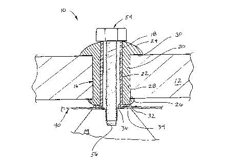
Figure 2 is a partial sectional view of the assembly illustrated in
Figure 1, taken generally through the center of the vibration mount.
Figure 3 is a detailed plan view of the conductive ground strap.
Figure 4 is a partial sectional view similar to Figure 2 further
including ground strap 40.
DETAILED DESCRIPTION OF THE PREFERRED EMBODIMENT
Referring now to the drawings, and in particular to Figure 1, a
mounting assembly made in accordance with the present invention, in this
instance used in securing an electronic control unit to a vehicle lr~"sn~ission
housing, is indicated generally at 10. The components of assembly 10 are
utilized to mechanically secure a protruding tab 12 of an electronic device
housing or package to an appropriately fashioned mounting boss 14 of a
powertrain or other vehicular component. Preferably, the electronic device
housing includes a plurality of tabs 12, each to be secured to a separale
mounting boss 14.
Vibration isolation or dampening between each boss 14 and
eleclronc package tab 12 is performed primarily by a vibration dampening
mount 16 having positioned therein a strengthening insert 18. The con-
figuration of mount 16 and insert 18 is illustrated more clearly in the cross-
sectional view of Figure 2. As shown therein, vibration dampening mount 16
includes a generally cylindrically shaped body 20 having an interior bore 22
formed therelhrough. Body 20 is positioned between an e,llaryed rounded
head 24 and a smaller enlarged foot 26, through which interior bore 22 also
extends. Head 24 is spaced along cylindrical body 20 from foot 26 so as to
retain tab 12 therebetween, dampener mount body 20,c,referalJly being retained
by friction in a suitable opening 28 which has been formed through tab 12. Tab
12 prereraL,ly fits securely between surfaces 30 and 32 of dampener head 24
and foot 26, respectively.
Vibration mount 16 is preferably made of a rubber or other
resilient material and in the present embodiment is an off-the-shelf product, part
21~9~5~
number J-20433-3, manufactured by Lord Corporation of elastomer B050A, a
synthetic rubber. Insert 18 is preferably formed of a rigid metallic material such
as steel and fits by press fit within dampener interior bore 22. Insert 18 is
likewise substantially cylindrically shaped, but having one flattened flared end34. When insert 18 is positioned within dampener 16, flared end 34 sits just
outside dampener foot 26 against a surface thereof opposite surface 32.
Returning back to Figure 1, an electrical grounding connection
between the electronic package and the vehicle chassis is made via a ground
strap 40. Ground strap 40 is made of a highly electrically conductive material,
in the presently prefer,ed embodiment a flexible metallic material such as a
heavy duty tinned copper braid, readily commercially available. Strap 40 is
.rererably of a length to fit substantially circumferentially around package ~ab12. As shown in Figure 3, the braided material of strap 40 has at each end,
a flat portion 42 for use in securing each end of strap 40 to package tab 12.
In the present embodiment each flat end portion 42 is formed by crimping flat
a length of tinned copper tube, with the braid material captivated therein, and
then punching a hole 44 therethrough. This configuration helps to prevent
fraying on the ends of strap 40 and provides a compression surface for
mounting screws. Alternately, however, flat portions 42 may be formed by
simply c- i" l,c ng flat an end of the metallic braid of strap 40 and forming hole 44
through the crimped braid.
Strap 40 is preferably secured to package tab 12 at each end
thereof, such as by rivets 46 which pass through holes 44 in strap 40 and holes
48 formed into package tab 12. The rivet head is expanded on the bottom side
of package tab 12 providing a permanent assembly as shown in detail in Figure
4. Rivets 46 are in the presenlly preferred embodiment formed of the same
material as the electronic package, preferably aluminum, so as to avoid thermal
expansion and contraction problems that may be created when riveting
dissimilar metals. Alternately, threaded fasteners could be used in place of
rivets 46 or a pair of rivets could be used to secure each end of strap 40.
Strap 40 preferably further has formed therein a further crimped
section 50, formed intermediate flat portions 42, in the present instance
21-~9~
- 5 -
approximately at the midpoint of strap 40. However, depending on the
configuration of package tab 12, and the manner in which strap 40 is wrapped
therearound, crimp 50 is formed on a portion of strap 40 wherein when strap
40 is disposed about tab 12, crimp 50 is aligned with insert 18.
Crimped area 50 further has formed therethrough, such as by
punching, an aperture 52. Aperture 52 is formed so as to be coincident with
opening formed through insert 18 such that a mounting bolt 54, again
preferably aluminum, passes through vibration mount 16 through strap 40 and
into a threaded bore 56 formed in mounting boss 14. Mounting boss 14
preferably has a machined surface against which the relatively soft material of
strap 40 mount is compressed, thereby providing an airtight electrical
connection in order to deter any impedance change due to corrosion. In order
to provide redundancy in the electrical grounding connection, a pair of straps
40 may be used, preterably disposed at approximately right angles to one
another.
Ground strap 40 is preferably manufactu, ed by slipping a number
of precut sections of hollow tubing onto a length of metallic braid sufficient to
make a number of straps 40. The tubing segments are spaced from one
another such that a first section of tubing may be crimped flat and then cut in
half to form a pair of flat end portions 42, each of which belongs to a se~.arale
strap 40. Into each end portion 42 is punched a hole 44, either prior to or after
separation. An ~ cent tube segment is crimped and punched to form
intermediate segment 50 and aperture 52. A next tubing segment is flattened
to form another end portion 42 and that of an adjoining strap 40.
In mounting tab 12 to boss 14, dampener 16 is preferably
i"se,lably forced into opening 28 of tab 12 by compressing foot 26. Insert 18
is then pre~erably forced upward into interior bore 22 of dampener 16 until
flared end 34 of insert 18 rests upon dampener foot 26. Aperture 52 of ground
strap 40 is then aligned between insert 18 opening 3~ and mounting boss 14
threaded bore 56. A threaded mounting bolt 54 is passed through insert 18
and aperture 52 and then into threaded engagement with the threaded bore 56
formed in mounting boss 14. Bolt 54 is tightened to provide an optimum
21~9A~3
amount of force against dampener head 24 with insert 18 preventing excessive
compression of dampener mount 16. Since insert opening 36 is not threaded,
bolt 54 fits therethrough by clearance fit. Once strap 40 is retained via aperture
52, end portions 42 are brought onto tab 12 and retained by threaded fasteners
5 46.
The present assembly 10 thus provides an improved means for
mounting a vibration sensitive electronic package to a vibration prone
mechanical component while also providing a suitable ground connection. The
design is such that mounting the electronic package without ground strap 40
10 is made less probable, thereby avoiding inadvertent omission of a separalely
attached ground strap.
The foregoing discussion discloses and describes an exemplary
embodiment of the present invention. One skilled in the art will readily
recognize from such discussion, and from the accompanying drawings and
15 claims, that various changes and modific~tions can be made therein without
depai ling from the spirit and scope of the invention as defined in the following
claims.