Language selection

Search

Patent 2149465 Summary

Third-party information liability

Some of the information on this Web page has been provided by external sources. The Government of Canada is not responsible for the accuracy, reliability or currency of the information supplied by external sources. Users wishing to rely upon this information should consult directly with the source of the information. Content provided by external sources is not subject to official languages, privacy and accessibility requirements.

Claims and Abstract availability

Any discrepancies in the text and image of the Claims and Abstract are due to differing posting times. Text of the Claims and Abstract are posted:

  • At the time the application is open to public inspection;
  • At the time of issue of the patent (grant).
(12) Patent: (11) CA 2149465
(54) English Title: TUBULAR ADAPTER
(54) French Title: ADAPTATEUR TUBULAIRE
Status: Deemed expired
Bibliographic Data
(51) International Patent Classification (IPC):
  • A61F 2/76 (2006.01)
  • A61F 2/00 (2006.01)
  • A61F 2/50 (2006.01)
(72) Inventors :
  • HIEMISCH, CHRISTIAN (Germany)
  • HOLZAPFEL, MARKUS (Germany)
(73) Owners :
  • OTTO BOCK ORTHOPADISCHE INDUSTRIE BESITZ- UND VERWALTUNGS KOMMANDITGESEL LSCHAFT (Germany)
(71) Applicants :
(74) Agent: KIRBY EADES GALE BAKER
(74) Associate agent:
(45) Issued: 2000-02-15
(22) Filed Date: 1995-05-16
(41) Open to Public Inspection: 1995-12-01
Examination requested: 1997-01-31
Availability of licence: N/A
(25) Language of filing: English

Patent Cooperation Treaty (PCT): No

(30) Application Priority Data:
Application No. Country/Territory Date
G 94 08 804.7 Germany 1994-05-30

Abstracts

English Abstract


The invention relates to a tubular adapter for clamping
connection with the end of a tubular part (4) of a modular
prosthesis, said adapter consisting of an axially slotted
connecting sleeve (2) circumferentially clampable by means
of a clamping bolt or the like and intended to receive tube
end (4), with one end of said sleeve abutted by an annular
coupling section (3) preferably having on its circumference
four equally spaced threaded holes (5), each hole being
designed to receive a coupling and adjusting bolt (clamping
bolt) and having an annular ball socket (6) provided endwise
to engage a ball collar of an adjusting core, said socket
extending in the coupling position on a projection designed
as a multi-surface pyramid into the clamping area of the
clamping bolts. To improve the connection between the
tubular adapter and the tubular part, it is proposed
according to the invention that free end section (7) of
connecting sleeve (2) opposite coupling section (3) be
provided on its inner annular surface with a plastic
clamping cuff (8).


Claims

Note: Claims are shown in the official language in which they were submitted.


4


Claims:


1. Tubular adapter for clamping connection with an end
of a tubular part of a modular prosthesis, comprising a
connecting sleeve including an axial slot, said connecting
sleeve being circumferentially clampable by a clamping
member which is connected to said connecting sleeve across
said axial slot, said connecting sleeve having an opening
to receive said end of said tubular part, a first end of
said connecting sleeve abutting upon an annular coupling
section which includes on its circumference four equally
spaced threaded holes, each threaded hole for receiving a
coupling and adjusting bolt, said annular coupling section
comprising an annular ball socket provided endwise to abut
a ball collar of an adjusting core and a clamping area
positioned adjacent said annular ball socket, said
connecting sleeve including a second end located opposite
said coupling section, said second end of said connecting
sleeve including an inner annular surface, and wherein a
plastic clamping cuff is positioned on said inner annular
surface of said second end of said connecting sleeve,
wherein said plastic clamping cuff is a separate ring
which is embedded in a region of said second end of said
connecting sleeve.
2. Tubular adapter for clamping connection with an end
of a tubular part of a modular prosthesis, comprising a
connecting sleeve including an axial slot, said connecting
sleeve being circumferentially clampable by a clamping
member which is connected to said connecting sleeve across
said axial slot, said connecting sleeve having an opening
to receive said end of said tubular part, a first end of
said connecting sleeve abutting upon an annular coupling
section which includes of its circumference four equally
spaced threaded holes, each threaded hole for receiving a
coupling and adjusting bolt, said annular coupling section
comprising an annular ball socket provided endwise to abut


5


a ball collar of an adjusting core and a clamping area
positioned adjacent said annular ball socket, said
connecting sleeve including a second end located opposite
said coupling section, said second end of said connecting
sleeve including an inner annular surface, and wherein a
plastic clamping cuff is positioned on said inner annular
surface of said second end of said connecting sleeve,
wherein an axial length of said plastic clamping cuff
roughly corresponds to one-fifth of an axial length of
said connecting sleeve.
3. A tubular adapter for use in a modular prosthesis,
comprising:
a connecting sleeve having first and second ends, and
a cylindrical bore extending within said connecting sleeve
from said second end to said first end for receiving a
tubular part of a modular prosthesis;
an axial slot in said connecting sleeve extending
from said second end of said connecting sleeve to a point
near said first end of said connecting sleeve;
a circumferential clamping means connected to an
external surface of said connecting sleeve and positioned
to clamp across said axial slot in said connecting sleeve;
an annular coupling means positioned at said first
end of said connecting sleeve, said annular coupling means
including
an annular ball socket designed to abut a ball
collar of an adjusting core and to receive a
multi-surface pyramid shaped core which extends from
said ball collar,
an interior clamping region positioned adjacent
said annular ball socket, and
a plurality of equally circumferentially spaced
threaded openings extending from an exterior surface
of said annular coupling means to said interior
clamping region; and


6


a plastic clamping cuff positioned on an inner
surface of said cylindrical bore of said connecting
sleeve in a region of said second end of said
connecting sleeve, said region of said second end of
said connecting sleeve having an annular groove
formed therein and wherein said plastic clamping cuff
is matched in size to said annular groove, said
plastic clamping cuff eliminating metallic contact
between said tubular part of said modular prosthesis
and said inner surface of said connecting sleeve in
said region of said second end of said connecting
sleeve.
4. A tubular adapter for use in a modular prosthesis
comprising:
a connecting sleeve having first and second ends, and
a cylindrical bore extending within said connecting-sleeve
from said second end to said first end for receiving a
tubular part of a modular prosthesis;
an axial slot in said connecting sleeve extending
from said second end of said connecting sleeve to a point
near said first end of said connecting sleeve;
a circumferential clamping means connected to an
external surface of said connecting sleeve and positioned
to clamp across said axial slot in said connecting sleeve;
an annular coupling means positioned at said first
end of said connecting sleeve said annular coupling means
including
an annular ball socket designed to abut a ball
collar of an adjusting core and to receive a
multi-surface pyramid shaped core which extends from
said ball collar,
an interior clamping region positioned adjacent
said,annular ball socket, and
a plurality of equally circumferentially spaced
threaded openings extending from an exterior surface


7


of said annular, coupling means to said interior
clamping region; and
a plastic clamping cuff positioned on an inner
surface of said cylindrical bore of said connecting
sleeve in a region of said second end of said
connecting sleeve, said region of said second end of
said connecting sleeve having an annular groove
formed therein and wherein said plastic clamping cuff
is a coating positioned within said annular groove,
said plastic clamping cuff eliminating metallic
contact between said tubular part of said modular
prosthesis and said inner surface of said connecting
sleeve in said region of said second end of said
connecting sleeve.
5. A tubular adapter for use in a modular prosthesis,
comprising:
a connecting sleeve having first and second ends, and
a cylindrical bore extending within said connecting sleeve
from said second end to said first end for receiving a
tubular part of a modular prosthesis:
an axial slot in said connecting sleeve extending
from said second end of said connecting sleeve to a point
near said first end of said connecting sleeve;
a circumferential clamping means connected to an
external surface of said connecting sleeve and positioned
to clamp across said axial slot in said connecting sleeve;
an annular coupling means positioned at said first
end of said connecting sleeve said annular coupling means
including
an annular ball socket designed to abut a ball
collar of an adjusting core and to receive a
multi-surface pyramid shaped core which extends
from said ball collar.
an interior clamping regions positioned adjacent
said annular ball socket, and


8


a plurality of equally circumferentially spaced
threaded openings extending from an exterior surface
of said annular coupling means to said interior
clamping region; and
a plastic clamping cuff positioned on an inner
surface of said cylindrical bore of said connecting
sleeve in a region of said second end of said
connecting sleeve wherein said plastic clamping cuff
has an axial dimension which is approximately one
fifth of an axial length of said connecting sleeve,
said plastic clamping cuff eliminating metallic
contact between said tubular part of said modular
prosthesis and said inner surface of said connecting
sleeve in said region of said second end of said
connecting sleeve.

Description

Note: Descriptions are shown in the official language in which they were submitted.


214946~
-


Tubular Adapter

The invention relates to a tubular adapter for clamping
connection with the end of a tubular part of a modular
prosthesis, consisting of an axially slotted connecting
sleeve, said sleeve being circumferentially clampable by
means of a clamping bolt or the like and designed to receive
the end of a tube, at one end of which sleeve an annular
coupling section abuts, said section preferably having on
its circumference four equally spaced threaded holes, each
to receive a coupling and adjusting bolt (clamping bolt) and
having an endwise annular ball socket to engage a ball
collar of an adjusting core, said socket, in the coupling
position, extending on a projection shaped as a multi-
surface pyramid into the clamping area of the clamping bolt.
An embodiment of this kind can be found in US Patent
3,659,294. Figures 3 and 4 in particular indicate that the
projection of the adjusting core is designed as a four-
surface pyramid, mounted standing on its point and centered
with respect to the ball collar. In the coupling position,
this projection extends through the annular ball socket of
the adapter into the vicinity of the clamping bolts, each of
which contacts one of the pyramid surfaces approximately
perpendicularly, and said bolts are therefore arranged with
their axes at an acute angle to the cross-sectional plane of
the tube.
The clamping bolts perform the coupling between the
adapter part and the adjusting core. At the same time,
however, the clamping bolts serve for adjusting the central
axis of the adjusting core with respect to the tube axis of
the tubular part. By loosening one clamping bolt and
tightening the opposite clamping bolt, the adjusting core
can be tilted with respect to the tubular adapter in a given
plane. By appropriate adjustment of the other two clamping
bolts, located opposite one another, pivoting can be
performed in a second plane perpendicular to the first
plane, with the ball collar of the adjusting core in each
case sliding in the annular ball socket of the adapter part.

214~465

_

The tubular adapter is usually made of steel or
titanium, while the tubular part is made of aluminum. In
the known embodiment, each end of the tubular part is slid
into a tubular adapter, with the connection being made in
the form of a press fit or a clamping connection. In the
latter case, the tubular adapter is provided with a clamping
strap that can be tightened by means of a bolt.
The goal of the invention is to improve the connection
between the tubular adapter and the tubular part.
This goal is achieved according to the invention by
virtue of the fact that the free end section of the
connecting sleeve opposite the coupling section is provided
with a plastic clamping cuff on its inner annular surface.
This invention is based on the following facts: By
virtue of the clamping process, the tubular part is impacted
at precisely the point at which the stresses applied by the
loading of the prosthesis are greatest. In addition, it has
been found that in known embodiments, each alternation in
load results in a relative movement between the connecting
sleeve and the tubular part, damaging the aluminum tube.
On the other hand, according to the invention, clamping
is no longer performed directly on the tube end but at a
distance therefrom, so that the tube section located between
the plastic clamping cuff and the coupling section can be
subjected to elastic deformation. In the area of maximum
relative movement between the connecting sleeve and the tube
end, metallic contact between these two parts is suppressed
by the plastic clamping cuff. Dynamic bending tests have
shown that the lifetime of these components is considerably
prolonged as a result.
The drawing shows an embodiment of the invention that
serves as an example.
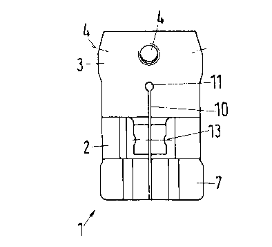
Figure 1 shows a tubular adapter in a side view; and
Figure 2 shows, on an enlarged scale, a lengthwise
section through the tubular adapter according to Figure 1
with a tubular part inserted.
The figure shows a tubular adapter 1 composed of a

2149465


connecting sleeve 2 and an annular coupling section 3
abutting one end of said sleeve. Figure 2 shows that
connecting sleeve 2 serves to receive an inserted tube end
4.
Coupling section 3 has on its circumference four
equally spaced threaded holes 5, each to receive a coupling
and adjusting bolt (clamping bolt) not shown in greater
detail in the drawing, and, endwise, an annular ball socket
6 to receive a ball collar of an adjusting core, not shown
in greater detail in the drawing, said core extending in the
coupling position on a projection designed as a multi-
surface pyramid into the clamping area of the clamping
bolts.
Connecting sleeve 2 is provided with an end section 7
at its end opposite coupling section 3, said section 7
surrounding a plastic clamping cuff 8 embedded in an annular
groove 9 of end section 7. Plastic clamping cuff 8 can be
placed loosely in annular groove 9. The dimensions of
plastic clamping cuff 8 and/or annular groove 9 are chosen
so that clamping takes place over the entire axial length of
connecting sleeve 2, but especially over the axial length of
plastic clamping cuff 8.
Connecting sleeve 2 has an axial slot 10 that merges
with an unloading bore 11. On both sides of axial slot 10,
connecting sleeve 2 is provided with a tab 12, said tabs
each having a bore 13, said bores being flush with one
another, to receive a clamping bolt, not shown in greater
detail.

Representative Drawing
A single figure which represents the drawing illustrating the invention.
Administrative Status

For a clearer understanding of the status of the application/patent presented on this page, the site Disclaimer , as well as the definitions for Patent , Administrative Status , Maintenance Fee  and Payment History  should be consulted.

Administrative Status

Title Date
Forecasted Issue Date 2000-02-15
(22) Filed 1995-05-16
(41) Open to Public Inspection 1995-12-01
Examination Requested 1997-01-31
(45) Issued 2000-02-15
Deemed Expired 2003-05-16

Abandonment History

Abandonment Date Reason Reinstatement Date
1999-04-19 FAILURE TO PAY FINAL FEE 1999-11-05

Payment History

Fee Type Anniversary Year Due Date Amount Paid Paid Date
Application Fee $0.00 1995-05-16
Registration of a document - section 124 $0.00 1996-01-25
Maintenance Fee - Application - New Act 2 1997-05-16 $100.00 1997-04-23
Maintenance Fee - Application - New Act 3 1998-05-19 $100.00 1998-04-09
Maintenance Fee - Application - New Act 4 1999-05-17 $100.00 1999-04-08
Reinstatement - Failure to pay final fee $200.00 1999-11-05
Final Fee $300.00 1999-11-05
Maintenance Fee - Patent - New Act 5 2000-05-16 $150.00 2000-04-26
Maintenance Fee - Patent - New Act 6 2001-05-16 $150.00 2001-04-12
Owners on Record

Note: Records showing the ownership history in alphabetical order.

Current Owners on Record
OTTO BOCK ORTHOPADISCHE INDUSTRIE BESITZ- UND VERWALTUNGS KOMMANDITGESEL LSCHAFT
Past Owners on Record
HIEMISCH, CHRISTIAN
HOLZAPFEL, MARKUS
Past Owners that do not appear in the "Owners on Record" listing will appear in other documentation within the application.
Documents

To view selected files, please enter reCAPTCHA code :


To view images, click a link in the Document Description column. To download the documents, select one or more checkboxes in the first column and then click the "Download Selected in PDF format (Zip Archive)" or the "Download Selected as Single PDF" button.

List of published and non-published patent-specific documents on the CPD .

If you have any difficulty accessing content, you can call the Client Service Centre at 1-866-997-1936 or send them an e-mail at CIPO Client Service Centre.


Document
Description 
Date
(yyyy-mm-dd) 
Number of pages   Size of Image (KB) 
Prosecution Correspondence 1995-07-26 1 25
Description 1995-12-01 3 135
Abstract 1995-12-01 1 27
Cover Page 1996-03-12 1 20
Claims 1995-12-01 1 37
Drawings 1995-12-01 2 30
Claims 1998-07-28 5 194
Cover Page 2000-01-24 1 37
Representative Drawing 2000-01-24 1 4
Representative Drawing 1998-08-20 1 23
Fees 1999-07-12 1 94
Prosecution-Amendment 1997-01-31 4 138
Prosecution-Amendment 1997-05-20 3 129
Correspondence 1998-10-19 4 172
Correspondence 1999-12-08 1 1
Correspondence 1999-11-05 1 53
Assignment 1995-05-16 6 206
Prosecution-Amendment 1997-01-31 4 138
Prosecution-Amendment 1997-05-20 3 128
Correspondence 1998-10-19 4 168
Assignment 1995-05-16 6 209
Fees 1997-04-23 1 28