Note: Descriptions are shown in the official language in which they were submitted.
- 2149~81
Description
AUTOMATIC POSITIVE HOOD SAFETY LOCK
5 Technical Field
This invention relates to an automatic safety lock for the hood of a
vehicle. More particularly, the invention relates to a hood safety lock which
automatically locks the hood in an open position when access to the vehicle engine or
related components is desired.
Back~round of the Invention
Various devices have been created to secure the hood of a vehicle in
an open position in order to allow the operator or maintenance personnel safe access
to- the engine. That is, personnel can work on the engine without fear of the hood,
15 which is often very heavy especially on larger vehicles like a truck, from prematurely
closing on the limbs or body of the personnel. For example, the prior art includes use
of a safety cable fixed to the hood of a truck. After the operator or maintenance
personnel lifts the hood, they can attach the cable which will become taught when the
hood moves approximately more than halfway closed. However, the safety cable
20 must be manually attached to the engine when the hood is fully opened. If theoperator forgets to do this, he risks serious danger. Likewise, if the truck breaks
down at night, the operator could burn his hands attempting to find the location on
the engine where the safety cable can be latched. Another solution to the problem of
premature hood closure includes use of a flat long bar which is fixed on one end to
25 the hood. As the hood is opened, the bar slides along a guide until a notch on the
bottom side of the bar drops into a slot. The notch locks the hood in an open
position. The maintenance personnel can then lift the bar to release the hood upon
completing the maintenance to the engine or related components. This solution takes
an extraordinary amount of space due to the travel associated with the hood. That is,
30 the bar must be exceptionally long, approximately two feet or longer. Additionally,
to retrofit existing trucks with this safety device requires cutting existing structure to
facilitate the bar as well as adding structure like a hinge bolt. Furthermore, the notch
in the support bar can be rendered ineffective by dirt, ice, or other cont~min~nts
associated with the working environment of a vehicle. Moreover, the maintenance
35 personnel may pinch or cut their hand when pulling the flat bar out of the slot upon
attempting to close the hood.
- 2149481
Summary of the Invention
The present invention is a compact automatic lock with a resetting
mech~ni~m. It is located away from the engine and is designed to replace an existing
bracket at a location where the hood hinge is pivotally connected to the vehicle5 frame. Consequently, the present invention can be readily adapted to existing trucks
because it is designed to replace existing support brackets for the hood hinge. When
the hood is open, the hood hinge pivots forward. The invention automatically falls
into the gap left by the hood hinge moving forward. Therefore, without any
assistance from the maintenance personnel or vehicle driver when the hood is
10 opened, the invention automatically prevents the hood from returning to a closed
position. The invention is located where the hood hinge is secured to a structural
member of the vehicle typically located away from the engine. Since the hood safety
lock is located away from the engine, there is little chance that the operator or
maintenance personnel will burn their limbs. Moreover, when the maintenance
15 persolmel or driver of the vehicle closes the hood, the invention automatically resets.
That is, when the hood is opened again, the invention will automatically prevent the
hood from closing.
Therefore, it is an object of the invention to have a hood safety lock
which automatically deploys when the hood is opened. Therefore, forgetfulness of20 the operator or maintenance personnel will not result in injury. Likewise, it is an
object of the invention to be located away from the engine. This prevents the driver
or maintenance personnel from burning their limbs when resetting the invention. It is
also an object of the invention to have a lock which automatically resets. Moreover,
it is an object of the invention to be readily adaptable to the structure of existing
25 vehicles, thereby allowing easy and cost-effective retrofit. Furtherrnore. it is an
object of the invention to be compact and lightweight.
Brief Description of the Drawings
Other objects and a fuller understanding of the invention may be had
30 by referring to the following description and claims, taken in conjunction with the
accompanying drawings in which:
Figure 1 A is a front view of the invention installed in a truck.
Figure lB is a front view of the invention attached to a vehicle frame.
Figure 2 is a rear view of the invention.
3~ Figure 3 is a side view of the invention when the hood is closed.
Figure 4 is a side view of the invention when the hood is in an open
position and the invelltion prevents the hood from closing.
- 21~9~1
.
Figure 5 is a side view of the invention when the hood is in an open
position and the invention is unlocked allowing the hood to be closed.
Detailed Description of the Invention
Referring now to the drawings for a better understanding of the
invention, Figure lA shows the invention installed in a truck. In a broad sense, the
invention comprises an automatic hood safety lock for a vehicle. Figure lA
demonstrates that the invention is located away from the engine. Typically, as shown
in Figure lA, the invention will be located under the hood 14 where the hood hinge
16 is located.
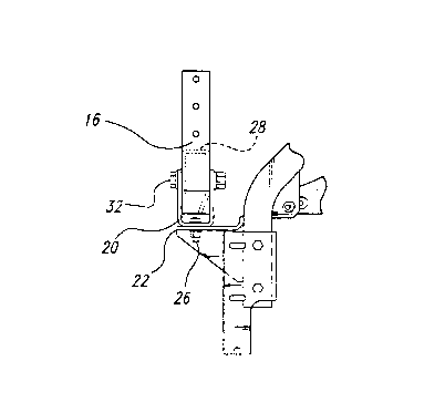
As will be observed in Figure lB, the invention is anchored to the
vehicle frame 22 through use of bolt 26. Therefore, the support bracket 20 remains
fixed in relation to the vehicle frame 22. The vehicle frame 22 can be any stationary
support structure associated with the vehicle.
From Figure 2 it can be seen that the swing arm 28 is co1mected to the
support bracket 20 by use of the swing arm pivot pin 32. The swing arm pivot pin 32
allows the swing arm 28 to pivot fore and aft. To facilitate the pivotal motion, a pin
38 is secured to the swing arm 28 and is spring loaded by a spring 36. The spring 36
is anchored to the support bracket 20 at the lower end. The point where the spring 36
20 is connected to the support bracket 20 is slightly forward of the point where the
spring 36 is attached to the pin 38. This results in a tension force drawing the swing
arm 28 toward the hood hinge 16 (not shown in Figure 2). This facilitates the
automatic action of the invention. That is, as the hood 14 is opened and the hood
hinge 16 moves as a result that it is fastened to the hood 14 by bolt 18 as shown in
25 Figure 3, the swing arm 28 also moves in the same direction until it is in a locked
position as shown in Figure 4. The tension force will also result in an audible noise
as the swing aml 28 comes to rest when the hood 14 is opened. The noise informs
the driver or maintenance that the invention is deployed and that the hood 14 islocked. The noise can be electronically generated with electrical amplification
30 equipment and proximity sensors informing the driver or maintenance personnel that
the swing arm 28 is in a locked position. Alternately. the noise can be made with a
simple mechanical device, for example, by using a spring 36 which has sufficienttension to cause the pin 38 to contact the support bracket 20 with sufficient force
when the hood 14 is opened resulting in an audible noise.
In Figure 2, the pin 38 can be seen to extend beyond the swing arm 28
on one side. This prevents the swing arm 28 from i:`alling too far when the hoodhinge 16 is in an open position as shown in Figure 4. That is~ the pin 38 follows the
`- 2149481
contour of the support bracket 20, shown by hidden lines in Figure 4, until the swing
arm 28 is in a locked position. Likewise, the extension of pin 38 also prevents the
swing arm 28 from pivoting too far when the lock is manually released to close the
hood 14 as shown in Figure 5. That is, the support bracket 20 acts as a stop for the
S extension of pin 38.
As will be observed from Figure 3, the swing arm 28 is positioned
against the hood hinge 16 when the hood 14 is closed. As discussed earlier, the f`act
that the spring 36 is slightly angled results in a tension force causing the s-ving arm
28 to be pressed against the hood hinge 16. Many different types of springs can be
10 utilized to create the tension force. For example, a coil spring concentric about shaft
38, a comb disk spring, or any other resilient biasing member can be used to cause
the swing arm 28 to be rotated when the hood is opened. Therefore, as the hood 14 is
opened and the hood hinge 16 is thereby pivoted around hinge pivot pin 30, the
spring 36 causes the swing arm 28 to move forward pivoting about the swing arm
15 pivot pin 32. As a result, the swing arm 28 is pulled forward by the spring 36 as the
hood hinge 16 is pivoted around the hinge pivot pin 30. The swing arm 28 continues
to move forward until the extension of pin 38 comes to rest against the support
bracket 20. This can be seen in Figure 4. With the swing arm 28 in the locked
position shown in Figure 4, the hood 14 cannot be closed. That is, should the wind
20 blow against the hood 14 or should maintenance personnel try~to close the hood 14
while someone is working on the vehicle 12, the swing arm 28 will prevent the hood
hinge 16 from moving. Since the hood hinge 16 is fastened to the hood 14 throughhood fastener 18, the hood 14 cannot close. When the repairs are complete, or the
maintenance personnel or driver has completed inspection of the engine, they can25 release the invention from a locked position by merely grabbing notch 40 shown in
Figure 2 and gently pulling upward. This will place the swing a1m 28 to a reset
position sho-vn in Figure 5. When the hood 14 is closed, the hood hinge 16 will
contact the bottom of the swing arm 28 causing the swing arm to automatically return
to the ready position shown in Figure 3. That is. the invention will automatically
30 return to the ready position so that when the hood 14 is again opened, the invention
will automatically return to the locked position shown in Figure 4, thereby preventing
premature closure of the hood 14. In this way, there is no possible way that safety
can be compromised by forgetfulness of the maintenance personnel or driver.
As can be seen from Figure 4, when the invention is in a locked
35 position with the hood 14 open, significant forces will be absorbed by the swing arm
28~ swing arm pivot pin 32, the support bracket 20, and the hinge pivot pin 30.
Therefore, the material of these parts should be of sufficient strength to ~,vithstand
`- 2149481
forces associated with wind blowing against the open hood 14, or alternately, the
forces associated with a maintenance personnel or driver attempting to close the hood
14 when the invention is in a locked position. Typically, the invention will be
manufactured from steel, but the actual material used will depend on the size of the
5 vehicle and corresponding size of the hood.
Although the invention has been described in its preferred form with a
certain degree of yarticularity, it is understood that the present disclosure of the
preferred form has been made only by way of example and numerous changes in the
details of the construction as well as the combination and arrangements of the parts
10 may be resorted to without departing from the spirit and the scope of the invention as
hereinafter claimed.