Language selection

Search

Patent 2149801 Summary

Third-party information liability

Some of the information on this Web page has been provided by external sources. The Government of Canada is not responsible for the accuracy, reliability or currency of the information supplied by external sources. Users wishing to rely upon this information should consult directly with the source of the information. Content provided by external sources is not subject to official languages, privacy and accessibility requirements.

Claims and Abstract availability

Any discrepancies in the text and image of the Claims and Abstract are due to differing posting times. Text of the Claims and Abstract are posted:

  • At the time the application is open to public inspection;
  • At the time of issue of the patent (grant).
(12) Patent: (11) CA 2149801
(54) English Title: METHOD FOR WATER-GRANULATING CALCIUM FERRITE SLAG
(54) French Title: METHODE POUR LA GRANULATION DE SCORIES DE FERRITE DE CALCIUM DANS UN COURANT AQUEUX
Status: Term Expired - Post Grant Beyond Limit
Bibliographic Data
(51) International Patent Classification (IPC):
  • B01J 2/02 (2006.01)
  • C22B 1/14 (2006.01)
  • C22B 7/04 (2006.01)
(72) Inventors :
  • YAMASHIRO, AKIYOSHI (Japan)
(73) Owners :
  • MITSUBISHI MATERIALS CORPORATION
(71) Applicants :
  • MITSUBISHI MATERIALS CORPORATION (Japan)
(74) Agent: MARKS & CLERK
(74) Associate agent:
(45) Issued: 2003-08-19
(22) Filed Date: 1995-05-19
(41) Open to Public Inspection: 1996-03-20
Examination requested: 2000-06-27
Availability of licence: N/A
Dedicated to the Public: N/A
(25) Language of filing: English

Patent Cooperation Treaty (PCT): No

(30) Application Priority Data:
Application No. Country/Territory Date
08/308,519 (United States of America) 1994-09-19

Abstracts

English Abstract

A method is disclosed for water-granulating calcium ferrite slag which is produced in copper converting processing and contains 10 to 30 weight % of CaO. In the method, water is caused to flow at a flow velocity of 7 to 25 m/sec, and the calcium ferrite slag is introduced into the water flow such that weight ratio of water to slag amounts to no less than 100. With this method, the occurrence of phreatic explosions can be effectively avoided.


French Abstract

Une méthode est divulguée pour la granulation de scories de ferrite de calcium dans un courant aqueux qui est produit lors du traitement de conversions de cuivre et contient de 10 à 30 % en poids de CaO. Dans la méthode, on fait couler l'eau à une vitesse d'écoulement de 7 à 25 m/s, et les scories de ferrite de calcium sont introduites dans l'écoulement d'eau de sorte que le rapport en poids eau/scories s'élève au moins à 100. Avec cette méthode, l'occurrence d'explosions phréatiques peut être évitée efficacement.

Claims

Note: Claims are shown in the official language in which they were submitted.

8
The embodiments of the invention in which an exclusive
property or privilege is claimed are defined as follows:
1. A method for water-granulating calcium ferrite slag
produced in copper-converting processing and containing 10 to 30
weight % of CaO, the method comprising the steps of:
causing water to flow at a flow velocity of 7 to 25 m/sec; and
introducing the calcium ferrite slag into said flow of water
such that the weight ratio of water to slag is no less than 100.
2. A method for water-granulating calcium ferrite slag
according to claim 1, wherein the calcium ferrite slag is
introduced into the water flow at the weight ratio of water to
slag of at least 200.
3. A method for water-granulating calcium ferrite slag
according to claim 1 or 2, wherein the calcium ferrite slag is
introduced into the water flow at the weight ratio of water to
slag of less than 400.
4. A method for water-granulating calcium ferrite slag
according to claim 1, 2 or 3, wherein said flow velocity is 10 to
15 m/sec.

Description

Note: Descriptions are shown in the official language in which they were submitted.


.-.. .. . 2149801
NETHOD FOR WATER-GRANULATING CALCIUM FERRITE SLAG
BACRGROUND OF THE INVENTION
Field of the Invention
The present invention pertains to a novel method for
water-granulating calcium ferrite slag produced during copper
converting operation.
Related Art
In the~ corper smelting process, high-temperature
silicate slag, which may contain, as principal components,
35-40 weight ~ of FeO, 30-35 weight % of SiO2, and 3-7 weight
% of CaO, is proAuce~ in a smelting furnace, while high-
temperature calcium ferrite slag (calcium-based slag), which
may contain, as principal components, 45-65 weight ~ of
Fe3O4, 10-30 weight % of CaO and 10-35 weight ~ of Cu2O, is
pro~llceA in a converting furnace. The both types of slag are
shattered into granules by bringing them into contact with a
large amount of water to effect rapid quenching. This
operation is, in general, called ~water-granulation" or
~granulation~.
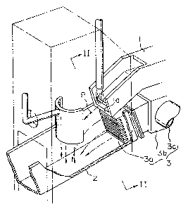
Figs. 1 and 2 depict a typical granulation apparatus
used for water-granul~ting the aforesaid slag. The
granulation apparatus includes a ~i~chArging launder 1 for
~i~çh~rgi~g slag; a receiving lAI-n~r 2 arranged below the
downstream end la of the ~i~ch~rging launder 1 so as to
extend in a discharging direction of the slag as i nAi c~ted by
the arrow P in Fig. l; and a water-jetting device 3 for
jetting granulating water` towards the slag, being discharged
-- . .
.

- 21gg801
--2--
from the discharging launder 1 to the receiving launder 2.
The water-jetting device 3 is constructed to have a large
number of elongated water outlets 3a (see Fig. 2), a water-
supplying tubular member 3b connected to the outlets in fluid
communication therewith, and a water conduit 3c connected to
the tubular member 3b at its lateral side so as to be in~
fluid communication therewith.
Conventionally, the water-granulation of the silicate
slag has bee~ carried out using the aforesaid granulation
apparatus in a relatively satisfactory manner. The water-
granulation of the calcium ferrite slag has been also carried
out by the same apparatus, but has been very difficult. For
example, when the operational conditions simil~r to those of
the water-granulation of the silicate slag are adopted for
the water-granulation of calcium ferrite slag, phreatic
explosions have frequently occurred.
SUMMARY OF ~HE lN Vk.. ~ lON
It is therefore the object of the present invention to
provide a water-granulation method for calcium ferrite slag,
by which phreatic explosions during the granulation can be
substantially obviated.
According to the invention, there is provided a method
for water-granulating calcium ferrite slag which is proAnce~
in a copp~r converting process and contains 10 to 30 weight %
of CaO, comprising-the steps of:
causing water to flow~ at a flow velocity of 7 to 25
mlsec; and
. .

2I~9801 . - -
introducing the calcium ferrite slag into the flow ofwater such that the weight ratio of water to slag amounts to
no less than 100.
With these procedures, the occurrence of phreatic
explosions during the water-granulation can be substantially
avoided. ~owçver, if either of the flow velocity or the
weight ratio of water to slag falls outside the numerical
ranges as specified herein, phreatic explosions frequently
occur.
In the foregoing, the water-granulation apparatus to be
used for carrying out the aforesaid method may be of an
arbitrary structure, and is not restricted to the
conventional apparatus as explained above.
BRIEF DESCRIPTION OF-TEE DR~WINGS
Fig. 1 is a partially cut-away perspective view of a
conventional water-granulation apparatus of slag; and
Fig. 2 is a schematic transverse cross-sectional view of
the apparatus of Fig. 1, taken along the line II-II in Fig.
1.
DESCRIPTION OF T~E PREFERRED EMBODl.~..~S OF THE lNV~ ON
A water-granulation method for calcium ferrite slag in
accordance with the present invention will be expl~;ne~ in
detail. In the water-granulation of calcium ferrite slag,
the granulation apparatus as shown in Figs. 1 and 2 may be
employed, although gran~lation apparatuses of other
cons~ructions could be used as well. In the granulation
.

2149801 - -
process, granulating water is supplied into the water outlets
3a via the conduit 3c and the -tubular member 3b. The
granulating water thus supplied is jetted out from the water
outlets 3a in a direction in which the receiving launder 2
extends. Furthermore, the high temperature calcium ferrite
slag is discharged from the discharging end la of -the
discharging launder 1 and is introduced into the water flow
being jetted out from the water outlets 3a. ~hus, the
calcium ferrite slag contacts the water, and is rapidly
guenched and water-granulated.
In the granulation method of the present invention, the
granulating water is caused to flow at a flow velocity
ranging from 7 to 25 mlsec, and the calcium ferrite slag is
introduced into the water flow such that the weight ratio of
water to slag amounts to no less than 100. In the foregoing,
the ~flow velocity~ is not an actual flow velocity, but an
apparent velocity obtained by dividing the flow rate of the
granulating water by the cross-sectional area of the water
outlets.
When the water-granulation is carried out under these
conditions, phreatic explosions during the water-granulation
can be substantially obviated. However, if either of the
flow velocity or the weight ratio of water to slag is set so
as to fall outside the aforesaid ranges, phreatic explosions
frequently occur, although the mechanism of the oc~ullence is
not known.
In the foregoing, it is prefera~le that the- flow
velocity of water range from 10 to 15 m/sec, while the weight

- - 2149801
- - . -.
s
ratio of water to slag be no less than 200. If the flow
velocity ~ee~ 15 mJsec, the facilities located downstream
will be subjected to increased wear. On the other hand, if
the flow velocity is less than 10 m/sec and the weight ratio
of water to slag is less than 200, considerably large lumps
of slag may be produced. Furthermore, it is preferable that
the weight ratio of water to slag be less than 400 si~ply
because the design of apparatuses for allowing a great weight
ratio exceedi~g 400 is not practical on a commercial and
industrial basis.
Next, the water-granulation method of calcium ferrite
slag in accordance with the present invention will be
explained in more detail by way of example.
Example
The water-granulation was carried out using water-
granulation apparatuses having a basic construction as
depicted in Figs. 1 and 2. First, the granulating water was
supplied into the conduits 3c so as to be jetted out from the
water outlets 3a into the receiving launder 2, at a variety
of predetermined flow velocities: 5, 7, 10, 15, 20, 25, 27,
and 30 m~sec The alteration of the flow velocity was
carried out by changing the construction of water outlets 3a.
Furthermore, the amount of the calcium ferrite slag to flow
out from the discharging launder 1 was also varied to attain
various weight ratios of water to slag: 30, 90, 100, 200,
300 and 400. Thus, the wate~ granulation was carried out for
various combinations of the flow velocities and slagJwater
-

- 21~g-~01
weight ratios, and the number of phreatic explosions which
occurred per day was observed for each respective condition
The results are set forth in Table 1.
As may be easily seen from Table 1, when the granulating
water was caused to flow at a flow velocity ranging from 7 to
25 m~sec, and when the calcium ferrite slag was introduced
into the water flow such that the weight ratio of water to
slag amounted to no less than 100, no phreatic- explosions
were observed' However, when either of the flow velocity or
the weight ratio of water to slag was set outside the
aforesaid ranges, phreatic explosions occurred. In
particular, even though the amount of water was increased, if
the water velocity e~r~eA~ 25 m/sec, phreatic explosions
occurred.

~`. 2149801 --- :--
- Table 1
- ~low Velocity . . - Water/Slag Occurrences of
~ (m/sec) Ratio Explosions (times)
5* 30* 5
- 90* 4
100* - -4
- 200* 2
300*
400*
7 30* 4
90* 3
100 none
200 . none
300 none
400 none
30* 4
- g0* 2
100 none
200 none
300 none
400 none
30* 4
'- 90* 2
100 none
200 none
300 none
400 none
30* 5
90* 4
100 none
200 ~one
300 none
400 none
27* 30* 6
90* 5
100* 5
200* 3
300* 2
400*
30* 30* 7
90* 6
100* 5
200* 3
300* 2
400*
~Note: The symbol ~*~ denotes a value falling outside the
claimed range of the invention)

Representative Drawing
A single figure which represents the drawing illustrating the invention.
Administrative Status

2024-08-01:As part of the Next Generation Patents (NGP) transition, the Canadian Patents Database (CPD) now contains a more detailed Event History, which replicates the Event Log of our new back-office solution.

Please note that "Inactive:" events refers to events no longer in use in our new back-office solution.

For a clearer understanding of the status of the application/patent presented on this page, the site Disclaimer , as well as the definitions for Patent , Event History , Maintenance Fee  and Payment History  should be consulted.

Event History

Description Date
Inactive: Expired (new Act pat) 2015-05-19
Inactive: IPC from MCD 2006-03-11
Grant by Issuance 2003-08-19
Inactive: Cover page published 2003-08-18
Amendment After Allowance Requirements Determined Compliant 2003-06-05
Letter Sent 2003-06-05
Pre-grant 2003-06-03
Inactive: Final fee received 2003-06-03
Amendment After Allowance (AAA) Received 2003-05-26
Inactive: Amendment after Allowance Fee Processed 2003-05-26
Letter Sent 2002-12-03
Notice of Allowance is Issued 2002-12-03
Inactive: Approved for allowance (AFA) 2002-11-18
Amendment Received - Voluntary Amendment 2001-02-12
Letter Sent 2000-07-18
Inactive: Status info is complete as of Log entry date 2000-07-18
Inactive: Application prosecuted on TS as of Log entry date 2000-07-18
Request for Examination Requirements Determined Compliant 2000-06-27
All Requirements for Examination Determined Compliant 2000-06-27
Application Published (Open to Public Inspection) 1996-03-20

Abandonment History

There is no abandonment history.

Maintenance Fee

The last payment was received on 2003-04-22

Note : If the full payment has not been received on or before the date indicated, a further fee may be required which may be one of the following

  • the reinstatement fee;
  • the late payment fee; or
  • additional fee to reverse deemed expiry.

Please refer to the CIPO Patent Fees web page to see all current fee amounts.

Owners on Record

Note: Records showing the ownership history in alphabetical order.

Current Owners on Record
MITSUBISHI MATERIALS CORPORATION
Past Owners on Record
AKIYOSHI YAMASHIRO
Past Owners that do not appear in the "Owners on Record" listing will appear in other documentation within the application.
Documents

To view selected files, please enter reCAPTCHA code :


To view images, click a link in the Document Description column. To download the documents, select one or more checkboxes in the first column and then click the "Download Selected in PDF format (Zip Archive)" or the "Download Selected as Single PDF" button.

List of published and non-published patent-specific documents on the CPD .

If you have any difficulty accessing content, you can call the Client Service Centre at 1-866-997-1936 or send them an e-mail at CIPO Client Service Centre.


Document
Description 
Date
(yyyy-mm-dd) 
Number of pages   Size of Image (KB) 
Claims 2003-05-26 1 24
Cover Page 2003-07-17 1 39
Abstract 1996-03-20 1 15
Description 1996-03-20 7 235
Cover Page 1996-05-10 1 17
Claims 1996-03-20 1 18
Drawings 1996-03-20 2 45
Representative drawing 1997-11-05 1 20
Representative drawing 2002-11-18 1 13
Acknowledgement of Request for Examination 2000-07-18 1 177
Commissioner's Notice - Application Found Allowable 2002-12-03 1 160
Correspondence 2003-06-03 1 31
Fees 1997-04-07 1 62