Language selection

Search

Patent 2150435 Summary

Third-party information liability

Some of the information on this Web page has been provided by external sources. The Government of Canada is not responsible for the accuracy, reliability or currency of the information supplied by external sources. Users wishing to rely upon this information should consult directly with the source of the information. Content provided by external sources is not subject to official languages, privacy and accessibility requirements.

Claims and Abstract availability

Any discrepancies in the text and image of the Claims and Abstract are due to differing posting times. Text of the Claims and Abstract are posted:

  • At the time the application is open to public inspection;
  • At the time of issue of the patent (grant).
(12) Patent: (11) CA 2150435
(54) English Title: PLASTIC COATING THREAD AND COUPLING ASSEMBLY
(54) French Title: ENSEMBLE D'ACCOUPLEMENT A FILETS RECOUVERTS DE PLASTIQUE
Status: Term Expired - Post Grant Beyond Limit
Bibliographic Data
(51) International Patent Classification (IPC):
  • F16L 15/00 (2006.01)
  • F16L 15/04 (2006.01)
  • F16L 58/18 (2006.01)
(72) Inventors :
  • NELSON, JOHN M. (United States of America)
  • WILLIS, RAY D. (United States of America)
(73) Owners :
  • TUBOSCOPE VETCO INTERNATIONAL, INC.
(71) Applicants :
  • TUBOSCOPE VETCO INTERNATIONAL, INC. (United States of America)
(74) Agent: RICHES, MCKENZIE & HERBERT LLP
(74) Associate agent:
(45) Issued: 2000-05-16
(22) Filed Date: 1995-05-29
(41) Open to Public Inspection: 1996-02-13
Examination requested: 1999-06-01
Availability of licence: N/A
Dedicated to the Public: N/A
(25) Language of filing: English

Patent Cooperation Treaty (PCT): No

(30) Application Priority Data:
Application No. Country/Territory Date
08/288,805 (United States of America) 1994-08-12

Abstracts

English Abstract

- 8 - A coupling assembly having an annular coupling with internal threads having a continuous plastic, corrosion- resistant coating. Opposed tubes are provided with a similar internal coating. The tubes have external threads inserted into the coupling with the internal and external threads being in threaded engagement. An annular gasket is provided of rigid material and is mounted between and in sealing engagement with opposed ends of the tubes within the coupling. The gasket has a continuous radial portion extending between the opposed ends of the tubes and in spaced apart relation thereto. O-rings are in sealing engagement with the tubing ends and the continuous radial portion of the gasket. A pair of opposed flanges extend from opposite sides of the continuous radial portion of the gasket and are in sealing contact with an interior surface portion of the tubes.


French Abstract

8 - Un ensemble de couplage comportant un coupleur annulaire avec un filetage intérieur ayant un revêtement continu en matière plastique résistant à la corrosion. Des tubes opposés sont munis d'un revêtement interne similaire. Les tubes ont des filets externes insérés dans le coupleur, les filets internes et externes étant en prise vissée. Un joint annulaire est muni d'un matériau rigide et est monté entre, et en contact d'étanchéité avec des extrémités opposées des tubes à l'intérieur du coupleur. Le joint d'étanchéité comporte une partie radiale continue s'étendant entre les extrémités opposées des tubes, et dans une relation espacée à celles-ci. Les joints toriques sont en contact étanche avec les extrémités des tubes et la partie radiale continue du joint d'étanchéité. Une paire de brides opposées s'étendent depuis des côtés opposés de la partie radiale continue du joint d'étanchéité et sont en contact étanche avec une partie de surface intérieure des tubes.

Claims

Note: Claims are shown in the official language in which they were submitted.

-6-
The embodiments of the invention in which
exclusive property or privilege is claimed are defined as
follows:
1. A coupling assembly comprising an annular
coupling having internal threads having a central portion
having a plastic corrosion-resistant coating and opposed
tubes having a continuous plastic, corrosion-resistant
coating and having external threads inserted into said
coupling with said internal threads, including said central
portion thereof, and said external threads being in
threaded engagement to produce a seal and a corrosion
barrier at said central portion of said annular coupling,
an annular gasket of rigid material mounted between and in
sealing engagement with opposed ends of said tubes within
said coupling, said gasket having a continuous radial
portion extending between said opposed ends of said tubes
and spaced apart from each said opposed ends of said tubes
a distance sufficient to receive a plurality of O-rings
mounted between each said tubing opposed ends and said
continuous radial portion of said gasket and in sealing
engagement with each said plurality of O-rings, a pair of
opposed flanges extending from opposite sides of said
continuous radial portion of said gasket and into sealing
contact with an interior surface portion of said tubes
extending from each said opposed end of said tubes.
2. The coupling assembly of claim 1, wherein
said continuous radial portion of said gasket has opposed
side surfaces each constituting bearing surfaces for each

-7-
said plurality of O-rings resulting from application of
compressive force thereto by said tube ends.
3. The coupling assembly of claim 2, wherein
said opposed side surfaces of said continuous radial
portion of said gasket are substantially normal to said
exterior surface portion of each of said flanges.
4. The coupling assembly of claim 3, wherein
each said plurality of O-rings is contiguous to said
exterior surface portion of each of said flanges of said
gasket.
5. The coupling assembly of claims 1, 2, 3, or
4, wherein said flanges of said gasket have chamfered
edges.
6. The coupling assembly of claim 1, wherein
said flanges of said gasket have an outside diameter
greater than an inside diameter of said interior surface
portion of said tubes at an area of said sealing contact
therewith.

Description

Note: Descriptions are shown in the official language in which they were submitted.


~15043S
PLASTIC COATING THREAD AND COUPLING ASSEMBLY
BACKGROUND OF THE INVENTION
Field of the Invention
The invention relates to a coupling assembly for use in
coupling threaded, tubular articles.
Description of the Prior Art
In various threaded coupling applications for metal
tubular articles, such as in the gas and oil well extraction
and injection applications, it is necessary to couple
threaded, tubular articles in a manner that ensures a
reliable seal between the coupled ends of the tubular
articles and in addition protect the tube ends from
corrosion. It is typical in applications of this type, to
coat the interior surface of the tubular articles, including
the nose portion, and the coupling with plastic to protect
the interior surfaces of the metal tubing and coupling from
corrosion.
During coupling or make-up of the tubing in the field,
the corrosion-resistant plastic coating is subject to
mechanical damage and removal of portions of the coating,
particularly at or near the tubing ends. This coating
damage, and additionally the turbulent flow pattern that
occurs in this area of the tubular product during use, can
result in both abrasion and erosion of the exposed metal
along with subsequent corrosion as this exposed metal
contacts the corrosive fluid product in the tubing against
which the plastic coating was originally intended to protect.
In addition, it is advantageous to uncouple and reuse by
subsequent make-up tubular products of this type. Each time
the tubing is subjected to additional make-up, the threaded
portion of the tubing ends is distorted so that the tubing
ends extend a greater distance within the coupling during
each additional make-up. This dimensional change may require

21~0~3~
the use of a gasket insert of different dimensions than used
during the initial make-up of the tubing. This adds to the
cost and complexity of the make-up operation. In addition,
if the dimensions of the insert gasket are not correct,
effective sealing will not be achieved. Also, this may
result in the tubing ends damaging the gasket during make-up.
Specifically, if the gasket dimension i8 too short, which
limits effective contact with both tubing ends, proper
protection of the tubing ends will not be achieved.
Conversely, if the gasket is too long, it will be distorted
during makeup to limit the protection it can afford, reducing
the inside diameter at the coupling, and increasing the
turbulence of flow through the coupling.
SU~lARY OF THE INVENTION
It is accordingly an object of the present invention to
provide a plastic coated threaded coupling assembly, wherein
the plastic coating of the tubing of the assembly is
protected from mechanical damage and further protecting any
end portion of the tubing having coating damage by sealing it
against contact with corrosive fluids passing through the
coupling.
In addition, the present invention provides sufficient
flexibility to permit multiple make-up operations without
changing the dimensions of the gasket insert, while providing
protection to the tubing ends with respect to damage and
corrosion.
sroadly, in accordance with the invention, there is
provided a coupling assembly having an annular coupling.
Opposed tubes are provided having a continuous plastic,
corrosion-resistant coating, and having external threads
inserted into the coupling with the internal threads and
external threads being in threaded engagement. An annular
gasket is provided of rigid material and is mounted between
and in sealing engagement with opposed ends of the tubes

2150435
within the coupling. The gasket has a continuous radial
portion extending between the opposed ends of the tubes and
spaced apart from each opposed end of the tubes a distance
sufficient to receive a plurality of O-rings, each of which
are mounted between each of the tubing ends, and the
continuous radial portion of the gasket. The O-rings are in
sealing engagement with tubing ends and the continuous radial
portion of the gasket. A pair of opposed flanges extend from
opposite sides of the continuous radial portion of the gasket
and into sealing contact with an interior surface portion of
the tubes, extending from each opposed end of the tubes and
into sealing contact with an exterior surface portion of each
of these flanges.
The continuous radial portion of the gasket may have
opposed side surfaces each constituting bearing surfaces for
each plurality of O-rings upon the application of compressive
force to the O-rings by the tube ends. The opposed side
surfaces of the continuous radial portion of the gasket may
be substantially normal to the exterior surface portion of
each of the flanges of the gasket. Each of the O-rings may
be contiguous to the exterior surface portion of each of the
flanges of the gasket. The flanges of the gasket may have
chamfered edges. The internal threads of the annular
coupling may have a central portion with a plastic,
corrosion-resistant coating in threaded engagement with the
external threads of the opposed tubes. The flanges of the
gasket may have an outside diameter greater than an inside
diameter of the interior surface portion of the tubes at an
area of sealing contact with these flanges of the gasket.
BRIEF DESCRIPTION OF THE DRAWINGS
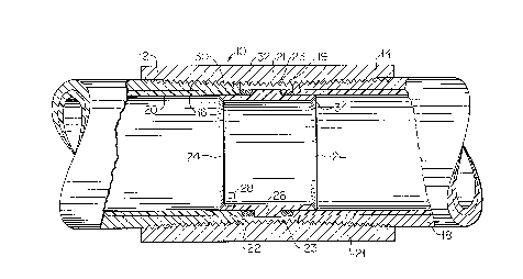
Figure 1 is cross sectional view of one embodiment of
the coupling assembly of the invention; and
Figure 2 is a cross sectional view of the gasket of the
coupling assembly of Figure 1.

~150935
DESCRIPTION OF THE PREFERRED EMBODIMENTS
With reference to the drawings, and for the present
Figure 1 thereof, there is shown one embodiment of a coupling
assembly in accordance with the invention, designated
generally as 10. The coupling assembly 10 has an annular
coupling 12 with tapered threads 14 in threaded engagement
with corresponding threads 16 on each of opposed, coupled
tubes 18 at the chamfer portion 19 thereof. The coupling 12
and tubes 18 may be any conventional alloy, such as carbon
steel.
The interior portion of tubes 18 and a center portion 21
of the coupling 12, have a continuous plastic,
corrosion-resistant coatings 20 and 23, respectively.
Alternately, the coupling 12 may not have this center portion
21 coated with plastic. Between the opposed ends of the
tubes 18 is a gasket 24. The gasket 24 is constructed from a
rigid material resistant to corrosive attack, such as
polyethylene or polypropylene. The gasket 24 is annular with
a continuous radial portion 26 with an opposed pair of
flanges 28 extending from opposite sides thereof, and into
contact with a marginal portion 30, extending from each
opposed end 22 of the tubes 18. Between the radial portion
26 of the gasket 24 and the ends 22 of the tubing 18, there
is provided two pair of a plurality of O-rings 32 of a
resilient or compressible material, such as rubber. The
pairs of O-rings 32 are compressed by the ends 22 of the
tubes to provide a tight seal between the tubing ends and the
gasket 24. In this manner, corrosive media passing through
the tubes 18 is prevented from contacting the ends 22 of
these tubes and the chamfer portion 19 from which the coating
20 may have been removed by mechanical damage. The ends 34
of the gasket 24 are chamfered to minimize turbulence of the
product flow which would increase pressure loss of product
passing through the coupling assembly to decrease effective

21504~S
product throughput. In addition, the chamfered gasket ends
34 will also improve the ability to pass standard oil field
tools through the coupling assembly.
The tubing ends are threaded into the coupling 12, a
threaded distance sufficient to compress the plurality of O-
rings 32 to an extent sufficient to provide the desired
sealing effect. The use of two pairs of a plurality of O-
rings in association with the gasket 24, enables the tube
ends to extend greater or lesser distances toward each other,
which depends upon distortion caused by reuse of the tubes,
while maintaining effective sealing.
As may be seen from this embodiment of the invention,
the chamfer ends 34 of the gasket 24 minimize turbulence of
product flow to improve the effectiveness of the seal and
prevent damage to the interior corrosion resistance plastic
coating of the tubing and in addition improve gasket
throughput. The use of two pairs of a plurality of 0-rings
in association with the marginal portion 26 of the gasket 24,
permits effective make-up of both new and used tubing by
accommodating variations in the penetration of the tubing
ends within the coupling, while maintaining an effective
seal. The marginal portion 30 of the tubing, which is in
sealing contact with the flanges of the gasket, provides for
sealing and protection of any portion of the tubing ends that
may have experienced coating damage and in this manner
provides protection from corrosion of these portions of the
tubing. An additional corrosion barrier is provided by the
engagement between plastic coating 23 of the coupling with
the plastic coating 20 of the chamfered portion 19 of the
tubing ends.

Representative Drawing
A single figure which represents the drawing illustrating the invention.
Administrative Status

2024-08-01:As part of the Next Generation Patents (NGP) transition, the Canadian Patents Database (CPD) now contains a more detailed Event History, which replicates the Event Log of our new back-office solution.

Please note that "Inactive:" events refers to events no longer in use in our new back-office solution.

For a clearer understanding of the status of the application/patent presented on this page, the site Disclaimer , as well as the definitions for Patent , Event History , Maintenance Fee  and Payment History  should be consulted.

Event History

Description Date
Inactive: Expired (new Act pat) 2015-05-29
Inactive: IPC from MCD 2006-03-11
Grant by Issuance 2000-05-16
Inactive: Cover page published 2000-05-15
Inactive: Final fee received 2000-02-16
Pre-grant 2000-02-16
Notice of Allowance is Issued 2000-01-12
Letter Sent 2000-01-12
Inactive: Approved for allowance (AFA) 1999-12-21
Amendment Received - Voluntary Amendment 1999-11-17
Inactive: Application prosecuted on TS as of Log entry date 1999-07-19
Letter Sent 1999-07-19
Inactive: Status info is complete as of Log entry date 1999-07-19
All Requirements for Examination Determined Compliant 1999-06-01
Request for Examination Requirements Determined Compliant 1999-06-01
Application Published (Open to Public Inspection) 1996-02-13

Abandonment History

There is no abandonment history.

Maintenance Fee

The last payment was received on 2000-05-04

Note : If the full payment has not been received on or before the date indicated, a further fee may be required which may be one of the following

  • the reinstatement fee;
  • the late payment fee; or
  • additional fee to reverse deemed expiry.

Patent fees are adjusted on the 1st of January every year. The amounts above are the current amounts if received by December 31 of the current year.
Please refer to the CIPO Patent Fees web page to see all current fee amounts.

Owners on Record

Note: Records showing the ownership history in alphabetical order.

Current Owners on Record
TUBOSCOPE VETCO INTERNATIONAL, INC.
Past Owners on Record
JOHN M. NELSON
RAY D. WILLIS
Past Owners that do not appear in the "Owners on Record" listing will appear in other documentation within the application.
Documents

To view selected files, please enter reCAPTCHA code :


To view images, click a link in the Document Description column (Temporarily unavailable). To download the documents, select one or more checkboxes in the first column and then click the "Download Selected in PDF format (Zip Archive)" or the "Download Selected as Single PDF" button.

List of published and non-published patent-specific documents on the CPD .

If you have any difficulty accessing content, you can call the Client Service Centre at 1-866-997-1936 or send them an e-mail at CIPO Client Service Centre.

({010=All Documents, 020=As Filed, 030=As Open to Public Inspection, 040=At Issuance, 050=Examination, 060=Incoming Correspondence, 070=Miscellaneous, 080=Outgoing Correspondence, 090=Payment})


Document
Description 
Date
(yyyy-mm-dd) 
Number of pages   Size of Image (KB) 
Abstract 1996-02-12 1 25
Description 1996-02-12 5 236
Claims 1996-02-12 2 61
Drawings 1996-02-12 1 39
Claims 1999-11-16 2 61
Representative drawing 2000-04-18 1 17
Representative drawing 1999-06-22 1 28
Acknowledgement of Request for Examination 1999-07-18 1 179
Commissioner's Notice - Application Found Allowable 2000-01-11 1 166
Correspondence 2000-02-15 1 37
Fees 2000-05-03 1 38
Fees 1998-05-07 1 38
Fees 1999-05-03 1 36
Fees 1997-04-21 1 48