Note: Descriptions are shown in the official language in which they were submitted.
215 0760
R~ ~OUND OF THE INVENTION
1. Field of the Invention. The subject invention
relates to elongate non-linear tubes having at least two
longitudinal sections that are different from one another in
size, shape or composition. The tubes may be used for
structural support or for incorporation into a vehicular
exhaust system.
2. Description of the Prior Art. Prior art tubes
have many automotive and industrial uses. For example, prior
art tubes are used to transport exhaust gases produced by an
internal combustion engine. Prior art tubes also are used for
structural support, such as in frames of vehicles. Most tubes
have a circular cross-sectional shape. However, tubes can
assume any cross-sectional shape, and many prior art tubes used
for structural support are rectangular in cross-section.
Tubes often must assume a non-linear alignment. In
some environments, the required non-linear alignment can be
achieved with short linear lengths of tubing connected by
fittings. In other environments, such as vehicular exhaust
systems and structural supports, the tubes must be bent into
a very precisely defined non-linear shape. For example,
vehicular exhaust pipes typically must follow a very circuitous
path from the engine compartment of the vehicle to a location
215 076 D
on the vehicle where exhaust gases can be safely emitted.
Precisely located and dimensioned bends are required to bypass
other components of a vehicle with sufficient clearance to
avoid vibration related contact and heat related damage. A
small bending error at one end of an exhaust system can yield
a very substantial misalignment at the opposed end of the
exhaust system. Precision is even more important for tubes
used in structural applications. For example, bent tubes often
are used for the longitudinally extending side rails of the
support frames of vehicles. Engine mounts, suspension system
components and body components must be anchored to the support
frame at locations that are specified to very small tolerance
variatlons.
Most precision tube bending is carried out with a
programmable bender. The typical prior art bender includes a
bend die, a clamp die and a pressure die. The bend die
includes an arcuate surface about which the tube will be bent.
The pressure die is disposed radially outwardly from the bend
die and is capable of movement in a radial direction for
selectively clamping the tube against the bend die. The clamp
die also engages the tube and also is disposed radially
outwardly from the bend die. Initially the clamp die is
adjacent to the pressure die. However, the clamp die can be
rotated about the axis of the bend die to bend the tube about
the outer circumference of the bend die. The angular size of
2150760
the bend is determined by the amount of rotation of the clamp
die from its starting position.
The prior art programmable bender also includes a
collet that grips one end of the tube to be bent. The collet
functions to move the tube axially and rotationally pre-
programmed amounts relative to the bend die. Thus, the collet
ensures that each sequential bend in a tube is at the proper
spacing and the proper rotational orientation relative to the
preceding bend.
Each bend causes a stretching of metal on the outer
circumferential surface of the bend and a compression of metal
on the inner circumferential surface of the bend. To minimize
the effects of stretching, many prior art programmable benders
also include a pressure die boost which effectively functions
to push tubing into the bend and to thereby prevent excessive
stretching. Some benders include a collet boost to assist the
pressure die boost by pushing the pipe into the bend. Damage
during a bending operation also can be prevented by a mandrel
disposed inside the tube at the location of the bend.
Very effective prior art benders are shown in U.S.
Patent No. 4,732,025 and U.S. Patent No. 4,959,984 both of
which are assigned to the assignee of the subject invention.
The bender shown in U.S. Patent No. 4,732,025 includes all of
2150760
the operative components described in the preceding paragraph.
Additionally, the bender includes sensors which detect whether
the rotational movement of the bend die and the clamp die has
the intended effect. In particular, metallurgical
characteristics may vary from one tube to the next and from one
location to another along each tube. Most tubes will exhibit
some springback after the pressure exerted by the clamp die has
been released. The amount of springback can vary significantly
depending upon metallurgical characteristics of the particular
pipe. Thus, even though the bender may perform precisely the
same operation for two different pipes, the resulting bent
pipes may not have the same bent shapes due to different
springback. The bender shown in U.S. Patent No. 4,732,025
senses the actual position of bent portions of the pipe, and
compares the actual sensed position to a pre-specified
position. If necessary, the bender shown in U.S. Patent No.
4,732,025 can perform compensating bending operations to offset
differential springback. Different tubes will exhibit
different resistance to the bending and clamping forces exerted
thereon. For example, some tubes will yield easily in response
to bending forces and will generate excessive stretching in the
outer wall of the tube. The apparatus shown in U.S. Patent No.
4,959,984 will sense resistance and alter forces the pressure
die boost and/or with the collet boost assist to effectively
urge more or less of the tube into the bend. In this manner
the apparatus shown in U.S. Patent No. 4,959,984 is capable of
215076l~
highly precise bending due to the ability of the bender to
react to sensed conditions for the actual pipe being bent.
Hydroforming has been used to deform short sections
of prior art tubes. This process involves placing the short
section of tube in a mold cavity conforming to the desired
shape of the tube. The ends of the tube are then plugged, and
fluid under pressure is directed into the plugged tube. The
fluid causes the shape of the tube to change to conform to the
shape of the mold cavity.
In addition to meeting certain dimensional
tolerances, bent tube also must meet performance requirements.
For example, certain regions of a structural tube may be
particularly susceptible to vibration related damage, while
other regions of the same tube may be susceptible to corrosion
related damage. Some regions of a tube may include a specified
material or coating primarily for aesthetic appearance. Other
regions may require changes to the cross-sectional dimensions
or shape. Specifications are likely to vary significantly
along the length of a tube used for a vehicular frame. For
example, the required wall thickness, the required cross-
sectional shape and the required cross-sectional dimensions can
vary significantly in accordance with the nature of the load
being carried at a particular location on the tube. In other
instances, the required surface coating of a supporting tube
2150760
can vary significantly from one longitudinal location to the
next.
Prior art tubes have been uniform along their length.
This generally has required an over design of the tube so that
the entire tube is made to meet the greatest load encountered
anywhere along the length of the tube. Additionally, the
cross-sectional shape, dimensions and surface coating for the
entire bent tube typically have been dictated by the
requirements at the most critical location. This occasionally
requires compromises to be made at other locations along the
tube.
In view of the above, it is an object of the subject
invention to provide a non-linear tube that more nearly meets
the specified design criteria for each location along the tube.
It is another object of the subject invention to
provide a method of making a non-linear tube that more
accurately meets the specifications for the entire tube.
~UNMARY OF THE INVENTION
The subject invention is directed to an elongate
composite tube bent and/or hydroformed into a specified non-
linear configuration and/or a specified non-uniform cross-
sectional shape. The composite tube includes a plurality of
2150760
longitudinal segments integrally joined in end-to-end
relationship with one another. The joining of adjacent
longitudinal segments may be achieved with laser welding.
Each longitudinal segment of the tube is different
from each longitudinal segment adjacent thereto. The
differences between adjacent longitudinal segments may relate
to the type of metal material from which the segment is made,
the wall thicknesses of the tube, or the external dimensions
of the tube. Characteristics for the respective longitudinal
segments of the tube are selected in accordance with the
structural and performance specifications for that segment.
Preferably, the connections between longitudinal segments are
selected to lie on cross-sectionally uniform tangents between
adjacent bends of the non-linear tube. However, depending upon
the magnitude of the bend, certain joints between longitudinal
segments may be disposed within a bend.
The subject invention also is directed to a method
for making a non-linear tube that closely conforms to
structural and performance specifications at each location
along the tube. The method includes a first step of selecting
a plurality of linear tube segments having strength and
performance characteristics appropriate for selected locations
along the length of a specified bent tube. The tube segments
are cut to selected lengths and are securely connected in end-
- -
- 2~ 50760 ~ (
to-end relationship with one another. The connection of the
tube segments preferably is carried out by laser welding.
The joined linear tube segments may then be subjected to a
bending operation which may be carried out in a pre-
programmed bending apparatus. The apparatus may include at
least one bend die, at least one clamp die and at least one
pressure die conforming to cross-sectional shapes of the
composite tube at selected locations along the length. The
pre-programmed bender may then be operated to bend the
composite tube into a specified non-linear shape. The boost
pressure, clamping pressure and bending speed all may be
adjusted to conform to the metallurgical characteristics of
the particular segment of the composite tube being bent.
Various aspects of the bending operation may be sensed
during and after each bend to assess the actual results of
the bend and to adjust the bender as needed. The method may
also include the step of hydroforming the tube so that the
cross-sectional shape of at least one tube segment is
changed. The hydroforming may be carried out to create a
shape specifically configured for engaging a structural
support or a suspension system component of a vehicle frame.
In one broad aspect, therefore, the present invention
relates to a method for manufacturing an elongate non-linear
composite tube, said method comprising the steps of:
providing at least first and second elongate tube segments,
said first tube segment having bend resistance different
from said second tube segment; welding said first and second
--8--
~'~
.
~507BO ~ ~
tube segments in substantially end-to-end relationship to
define a linear composite tube; placing said linear composite
tube in a bending apparatus; and placing a first bend of a
preselected magnitude at a preselected location in a portion
of said composite tube by defined by said first tube segment
by exerting preselected forces on regions of said tube and
moving said tube at preselected speeds, said forces and said
speeds for placing said first bend being selected in
accordance with said bend resistance characteristics in said
first tube segment; and placing a second bend of a preselected
magnitude at a preselected location in a portion of said
composite tube defined by said second tube segment by exerting
preselected forces on regions of said tube and moving said
tube at preselected speeds, said forces and said speeds for
placing said second bend being selected in accordance with
said bend resistance characteristics in said second tube
segment and being different from said forces and said speeds
for placing said first bend in said composite tube.
In another broad aspect, the present invention relates to
a non-linear composite tube comprising a plurality of tube
segments securely connected in end to end relationship, each
said tube segment of said composite tube being formed from a
material different and having different bend resistance
characteristics from the tube segment adjacent thereto, said
composite tube having a plurality of bends formed therein,
including at least one bend in each of a plurality of said
tube segments, said bends being spaced from said connections
between said tube segments each bend having a shape wherein
the shape is related to the material and bend resistance
characteristics of each respective tube segment being bent.
-8(a)-
. jC
2 ~ 5 0 7 6 0
BRIEF DESCRIPTION OF THE DRAWINGS
FIG. 1 is a perspective view of the non-linear
composite tube of the subject invention.
-8(b)-
, ~~
~15076~
FIG. 2 is a top plan view of a first segment of the
composite tube of the subject invention.
FIG. 3 is an end elevational view of the first tube
segment.
FIG. 4 is a top plan view of a second segment of the
composite tube of the subject invention.
FIG. 5 is an end elevational view of the second tube
segment.
FIG. 6 is a top plan view of a third segment of the
10composite tube of the subject invention.
FIG. 7 is an end elevational view of the third
segment of tube.
FIG. 8 is a top plan view of a fourth segment of the
composite tube of the subject invention.
FIG. 9 is an end elevational view of the fourth tube
segment.
FIG. 10 is a side elevational view of a composite
tube of the subject invention prior to bending.
FIG. 11 is a cross-sectional view taken along line
10-10 in FIG. 5.
FIG. 12 is a cross-sectional view taken along line
12-12 in FIG. 1.
FIG. 13 is an end elevational view similar to FIGS.
3, 5, 7 and 9, but showing an alternate tube shape.
2150763
DET~TT.Tm DESCRIPTION OF THE PREFERRED EMBODINENT
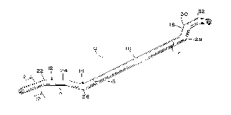
A non-linear composite tube in accordance with the
subject invention is identified generally by the numeral 10 in
FIG. 1. The non-linear composite tube 10 is formed from four
5dissimilar tube segments 12, 14, 16 and 18 respectively which
are laser welded in end-to-end relationship at seams 13, 15 and
17 respectively.
The tube segment 12 is initially linear and defines
a length L12 as shown in FIG. 2. The tube segment 14 is of
10circular cross-section, and defines a diameter D12 and a tube
thickness T12 as shown most clearly in FIG. 3.
The tube segment 14, as shown in FIGS. 4 and 5, also
is initially linear and defines a length L14. The tube segment
14 has a diameter D14 as shown in FIG. 5, which is slightly
15less than the diameter D12 for the tube segment 12 shown in
FIG. 3. Additionally, the tube segment 14 has a thickness T14
which is slightly less than the thickness T12 for the tube
segment 12 depicted in FIG. 3.
20The tube segment 16, as shown most clearly in FIGS.
6 and 7, also is initially linear, but defines a length L16
which is significantly greater than the corresponding linear
lengths of the tube segments 12 and 14. The diameter D16 and
thickness T16 of the tube segment 16 are approximately equal
--10--
~ - - ~
215076!~
the corresponding diameter D14 and thickness T14 of the tube
segment 14. However, the tube segment 16 is formed a different
type of metallic material.
As shown in FIGS. 8 and 9, the tube segment 18 is
initially linear and defines a length L18 which is less than
the length L16 of the tube segment 16 shown in FIG. 6. The
tube segment 18 defines a diameter D18 which equals the
diameter D16 on tube segment 16 and a thickness T18 which is
greater than the corresponding thickness T16 on tube segment
16. Additionally, tube segment 18 is provided with a thin
anti-corrosion coating thereon.
As shown in FIGS. 10 and 11, the tube segments 12,
14, 16 and 18 are laser welded to one another in end-to-end
relationship to define the weld seams 13, 15 and 17
respectively, as noted above. In this orientation, the inner
and outer walls include minor discontinuities in proximity to
the laser weld seams 13 and 15. However, the respective
thicknesses of the tube segments 12, 14 and 16 are selected to
ensure sufficient end-to-end contact area for achieving
structurally secure laser welds.
The linear composite tube 10 shown in FIGS. 10 and
11 is presented to a programmable bender for precisely placing
bends 22, 24, 26, 28, 30 and 32 in the composite tube 10. As
21~076o
illustrated clearly in FIG. 1, the lengths of the respective
tube segments 12, 14, 16 and 18 are selected to ensure that the
weld seams 13, 15 and 17 will lie within tangents between
adjacent respective bends 22, 24, 26 and 28 and 30 and 32
placed in the composite tube 10 by the programmable bender.
Thus, the weld seams 13, 15 and 17 will not be subjected to
stretching or compression by the bending apparatus.
The different diameter and thickness dimensions for
the tube segments 12, 14, 16 and 18 are selected in view of
structural performance requirements for the composite tube 10
at various locations along its length. For example, if the
composite tube 10 is used as a side rail in a vehicular frame,
the tube segments 12, 16 and 18 may have dimensions selected
to accommodate bending moments and other forces exerted by
suspension system components mounted nearby. The tube segment
18 may be at a location likely to be visually observed or to
be subjected to exposure to moisture and de-icing chemicals.
Hence, a special coating may be applied to tube segment 18.
The dimensions of various tube segments also may be selected
in view of the number of holes or features installed into the
composite tube 10 to support other frame components and/or
other parts of the vehicle.
The different dimensions and materials used for the
composite tube 10 will result in vastly different resistances
-12-
2150760
in response to bending forces. As a result, the bending of
composite tube 10 from the linear alignment shown in FIGS. 10
and 11 to the non-linear alignment shown in FIG. 1 preferably
is carried out with a bender as shown in the above referenced
U.S. Patent No. 4,732,025 and U.S. Patent No. 4,959,984. In
addition to sensing certain characteristics during the bending
operation, the bender is programmed to alter bending speed and
forces exerted by the pressure die, the pressure die boost and
the collet boost assist in view of known dimensional and
material differences at the locations at which each sequential
bend will take place. Thus, bends placed in the tube segments
with larger cross-sections or thicker pipe walls may be carried
out at different bends in thinner pipes. Additionally, boost
pressure may be increased for bends carried out in certain tube
segments. These variations in pressure and bend speed can be
pre-programmed to approximate anticipated reactions of the
different tube segments 12, 14, 16 and 18 to the bender.
However, conditions sensed by the programmable bender, as shown
in U.S. Patent No. 4,732,025 or in U.S. Patent No. 4,959,984
effectively enable a fine tuning of bending conditions in
response to the particular tube segment being bent.
The method may further include the step subjecting
the composite tube 10 to hydroforming to deform selected
locations along the tube. For example, as shown in FIG. 12 at
least one location along tube segment 12 may be hydroformed to
-13-
~ 2150760
define a flat 32 to which another structural element may be
mounted. When the composite tube 10 is used as a side rail for
a vehicular frame, flat 32 may be used to mount a suspension
system component or an engine mount. Other hydroformed shapes
may be provided at other locations along the length of
composite pipe 10. Advantageously, hydroforming enables
conventional circular pipes to be used for side rails, with
hydroformed flats at specified locations as needed. Circular
cross-section pipes often provide for easier three dimensional
bending than the rectangular pipes that are more commonly used
for side rails and other structural applications. However, as
shown in FIG. 13, a composite tube 10A of rectangular cross-
section can be provided with dissimilar tube segments in
accordance with the method described above.
While the invention has been described with respect
to a preferred embodiment, it is apparent that various changes
can be made without departing from the scope of the invention
as defined by the appended claims. For example, circular tubes
are shown in the accompanying drawings. However, tubes with
rectangular or oval cross-sections are within the scope of the
invention. Additionally, the attached drawings show most
differences relating to cross-sectional dimensions. However,
the tube segments may be cross-sectionally identical, but
differences between tube segments may relate to the material
from which the tube segments are formed and/or coatings applied
thereto. Additionally, FIG. 1 above shows one hypothetical
215~760
non-linear configuration. Other vastly different non-linear
configurations may be provided. These and other changes will
be apparent to the person skilled in the art after having read
the subject invention disclosure.