Note: Descriptions are shown in the official language in which they were submitted.
21SOg~
WO94/15076 PCT~S93/11850
OPEN GEAR 8ET LUBRIC~TION 8YSTEM
The present invention relates to a system for
the lubrication of an open gear set and, more
particularly, to a lubrication system which permits
the lubricant to be recirculated and reused.
In the mechanical transmission of power, large
open gear sets are frequently employed, particularly
in plants having large mills, kilns and the like.
Lubricants conventionally used for open gear sets
generally possess good adhesive properties to assure
that a film of lubricant is maintained on the contact
surfaces of the gear teeth. In the usual case, to
lubricate an open gear set, the lubricant is
generally applied using an all-loss method.
At present, open gears are lubricated with heavy
asphaltic lubricants which are applied continuously
by a paddle wheel or periodically by a system known
to those skilled in the art as a Farval system,
usually once every 15 to 20 minutes. Although such
systems are generally acceptable, a number of
problems have surfaced in recent years. One such
problem stems from the fact that most sprayed-on
lubricants are diluted with a solvent. As may be
appreciated, with today's heightened concern for the
environment, the presence of such solvents
necessitate that special handling procedures for
waste lubricants be employed. From a lubrication
standpoint, when premature evaporation of the solvent
occurs, pumping problems are often encountered even
before the lubricant is applied. Since presently
employed open gear lubricants are all-loss materials,
following their application, they become a hazardous
waste material. Moreover, leaked or spilled open
gear lubricants, due to their inherent tackiness, are
difficult to clean up. In states where disposal is
~0~76 PCT~S93111850 -
g ~ -2-
strictly regulated, the cost of proper disposal of
used open gear lubricants may run in excess of
$200,ooo, annually, for the average plant, and can be
expected to increase in the future.
From a mech~n;cal standpoint, much of the wear
which occurs in open gear sets is caused by a
combination of airborne abrasive dust and the present
"feast-or-famine" method of periodic lubricant
application. As can be appreciated by those skilled
in the art, when lubricants are applied using a form
of periodic application, the film so applied will
usually vary from being somewhat excessive, just
after application, to being somewhat inadequate, just
prior to the next application.
Therefore what is needed is an open gear
lubricating system which overcomes the aforementioned
problems and, in particular, is acceptable to open
gear builders, employs a lubricant which has recycle
capability, negligible environmental impact, is cost
effective, permits easy clean up, prevents gear wear
and offers improved power transmission efficiency.
In accordance with the present invention, there
is provided a recirculatory lubrication system for
applying a film of lubricant to an open gear set
having a pinion gear and a bull gear in me~h;ng
engagement with the pinion gear, the open gear set at
least substantially enclosed by a gear set cover
having a lower portion for collecting lubricant
therein. The lubrication system includes a lubricant
reservoir, a lubricant supply line, having a first
end in fluid communication with the supply port of
the reservoir, a lubricant distribution header having
a first end of in fluid communication with the second
end of the supply line, the header having a plurality
of lubricant feed orifices positioned along the
21~0~6
W094/15076 PCT~S9~/11850
--3--
length of the header, the feed orifices effective in
applying the film of lubricant onto the gear set, a
first lubricant return line having a first end in
fluid communication with the lower portion of the
gear set cover, a filter assembly, having an inlet
and an outlet, the inlet of the filter assembly in
fluid communication with the second end of the first
lubricant return line, the filter assembly having at
least one filter element positioned therein for
removing particles entrained in the lubricant and a
second lubricant return line having a first end in
fluid communication with the outlet of the filter
assembly and a second end in fluid communication with
the lubricant return port of the reservoir.
Also provided is a process for applying a film
of lubricant to an open gear set having a pinion gear
and a bull gear in meshing engagement with the pinion
gear, the open gear set at least substantially
enclosed by a gear set cover having a lower portion
for collecting lubricant therein, including the steps
of: (a) pumping the lubricant onto the open gear set,
(b) collecting the lubricant pumped in step (a) as
the lubricant drains from the open gear set to the
lower portion of the gear set cover, (c) transferring
the lubricant from the reservoir to a filter
assembly, (d) filtering the lubricant transferred in
step (c) to remove particles entrained in the
lubricant, (e) transferring the filtered lubricant to
a reservoir and (f) repeating steps (a) through (e) a
plurality of times.
Reference may now be had to the following
detailed description of exemplary embodiments of the
inventive recirculatory lubrication system, taken in
conjunction with the accompanying drawings, in which:
WO94/15076 PCT~S93/11850 -
21~26
Fig. 1 presents, schematically, a system for
lubricating an open gear set, in accordance with the
present invention.
Fig. 2 presents a perspective view of a
lubricant distribution header for use in the practice
of the present invention.
Fig. 3 presents a detailed schematic view of a
system for lubricating an open gear set, including
details of a preferred electro-pneumatic control
system, in accordance with the present invention.
Fig. 4 presents, schematically, another
embodiment of a system for lubricating an open gear
set, in accordance with the present invention.
Fig. 5 presents another embodiment of a
lubricant distribution header for use in the practice
of the present invention.
The present invention is best understood by
reference to the appended figures, which are given by
way of example and not of limitation.
As will become more fully appreciated, the
lubrication system of the present invention seeks to
solve the problems associated with the use of
traditional solvent-diluted asphaltic open gear
lubricants and their all-loss methods of application.
Advantageously, rather than employ a solvent-diluted
asphaltic open gear lubricant, a low pour point, pure
synthetic lubricant, containing no wax, solvents,
black oils, or any other hazardous material, is used.
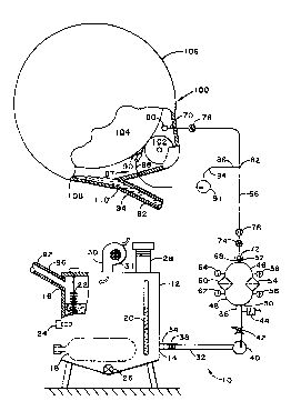
Referring now to Fig. 1, a schematic depiction
of one embodiment of a system 10 for lubricating an
open gear set, in accordance with the present
invention, is presented. Open gear set 100 includes
a pinion gear 102 and a bull gear 104 in meshing
engagement with pinion gear 102. Open gear set 100
is shown to be enclosed by a gear set cover 106 which
215~8~6
WO94115076 PCT~S93/11850
-5-
has a lower portion 108 for collecting lubricanttherein. Lubricant reservoir 12 is used to assure
that adequate supply of synthetic open gear lubricant
is available during operation of the open gear set
100. In a typical plant installation, such as a mill
or kiln operation employing open gear set 100, the
open gear set 100 might be located on the shop floor,
with reservoir 12 located in the basement below
together with attendant hardware and controls,
although other installation configurations are
readily envisioned. Reservoir capacities within the
range of from about 150 gallons to about 300 gallons
are generally preferred, with a reservoir capacity of
about 200 gallons being suitable for the typical open
gear set system.
Lubricant reservoir 12 is shown in Fig. 1 to
include lubricant supply port 14 and lubricant return
port 16. Lubricant reservoir 12 may also be equipped
with a reservoir sight glass 20 so that plant
personnel may readily observe that an adequate supply
of the synthetic open gear lubricant is present.
Optionally, a low lubricant level alarm 24 may be
installed in reservoir 12 and wired into a safety
shut-down system or visual or audible alarm system
(not shown) to further guard against operation in the
absence of an adequate supply of lubricant. Also, to
assure that the operational viscosity of the
synthetic lubricant within reservoir 12 is controlled
within an optimal range of values, thermostatically-
controlled reservoir heater 18 is provided. Amaximum watt density of 0.0124 watts per mm2 (8 watts
per square inch) is preferred for reservoir heater
18. Controlling the temperature of reservoir 12 to
38OC (100F). has been found to provide a good level
W094/15076 i -6- PCT~S93111850 -
215~2~
of operability in the practice of the present
invention.
To aid in the periodic cleaning of reservoir 12,
a 3-inch (or larger) ball valve drain 26 is provided.
As a further aid in cleaning reservoir 12, large
clean-out panels (not shown) can be fitted to each
side of reservoir 12 to permit the easy removal of
settled dust and debris. Reservoir 12 further
includes a fill pipe 28, which may be fabricated from
a 4-inch pipe fitting, as is preferred, to facilitate
the pouring of relatively heavy synthetic lubricant
into the reservoir. Fill pipe 28 should be at least
152 mm to 203 mm (6 inches to 8 inches) above the top
of reservoir 12, so that any dust that settles on
reservoir 12 will not cover the cap or threads of
fill pipe 28. An alternate method of adding oil to
reservoir 12 would be to use a quick- connect fitting
(not shown) on the fill pipe 28 so that reservoir 12
would not require opening to a potentially dusty
environment, permitting lubricant to be pumped from a
drum into reservoir 12. In order to reduce the
energy requirements of the system of the present
invention, reservoir 12 may be insulated to reduce
heat loss.
Connected to supply port 14 of reservoir 12 is a
first lubricant supply line 32 having a first end 34
in fluid communication with supply port 14 and a
second end 36. As is preferred, first lubricant
supply line 32 is positioned at least 127 or 152 mm
(5 or six inches) from the bottom of reservoir 12 to
avoid picking up settled particulate material.
Second end 36 of first lubricant supply line 32 is
connected to filter assembly 46. As is preferred,
filter assembly 46 includes a filter housing 48
having an inlet 50 and an outlet 52, inlet 50 being
~150~6
W094/15076 PCT~S93/11850
in fluid communication with second end 36 of first
lubricant supply line 32. Filter housing 48 has at
least one lO ~m filter element 54 positioned therein
for removing particles entrained in the lubricant.
Still more preferred is a dual filter assembly 46
having two lO ~m filter elements 54 and 60 positioned
within filter housing 48. A dual filter assembly 46
is preferred as it permits filter elements to be
changed without shutdown of the lubrication system
and gear set. A particularly preferred dual full-
flow lO ~m filter assembly is available from Parker
Co. (Part No. DIL2-2-lOB-PM-35-YEYE-ll). Gauges 56,
58, 62 and 64 may be mounted as shown in Fig. l so
that filter pressure drops can be monitored.
Still referring to Fig. l, first lubricant
supply line 32 is shown having a pump 40 installed
therein. Pump 40 is an air operated, double
diaphragm pump, such a pump available from W. W.
Grainger Company (Part No. 2P-348). Also installed
within first lubricant supply line 32 is flow
regulator 42, which may be set, as is preferred, to a
rate on the order of about one gallon per minute. To
provide a further measure of safety to the system and
gear set which it lubricates, a pressure alarm 44 is
fitted between pump 40 and filter assembly 46 to
alert maintenance personnel that a filter element
change is required.
A second lubricant supply line 66 having a first
end 68 in fluid communication with outlet 52 of
filter housing 48 is used to transfer lubricant to
hollow elongated lubricant distribution header 80.
Second lubricant supply line 66 is shown having two
- star wheel visual flow detectors 74 and 76 installed
just after filter assembly 46 and just before
lubricant distribution header 80, respectively. Also
WO94/15076 PCT~S93/11850 -
2150~26
installed in second lubricant supply line 66 is
magnetic flow detector 76 to alert operating
personnel when lubricant flow is stopped for any
reason. A check valve 68 is also provided to prevent
the possibility that a reverse flow of lubricant
could occur.
One embodiment of a lubricant distribution
header 80 is shown in a perspective view in Fig. 2.
As indicated in Fig. 2, the second end 70 of second
lubricant supply line 66 is connected to the first
end 83 of lubrication distribution header 80 so as to
in fluid communication therewith. Lubrication
distribution header 80 has a plurality of lubricant
feed orifices 81 positioned along the length of
lubrication distribution header 80. Lubricant feed
orifices 81 are sized and positioned to be effective
in applying an even film of lubricant across pinion
gear 102 for transfer to bull gear 104 during the
meshing of the pinion and bull gears 102 and 104.
Alternatively, as may be appreciated by those skilled
in the art, lubricant feed orifices 81 may be
positioned to apply a film of lubricant across bull
gear 104 for transfer to pinion gear 102 during the
~-~h ing of the bull and pinion gears, 104 and 102
respectively. The second end 85 of lubrication
distribution header 80 is shown to be sealed-off by
plug 87. As shown, when viewed from first end 83 to
second end 85 lubricant distribution header 80
employs a series of progressively larger feed
orifices 81, although other designs have proven to be
effective, as will be described below.
Referring again to Fig. 1, an optional auxiliary
lubrication system 87 is shown. Auxiliary
lubrication system 87 is advantageously employed for
gear mesh lubrication at the initiation of gear set
2 6
W094/15076 PCT~S93/11850
rotation (cold start-up). Auxiliary lubrication
system 87 includes a third lubricant supply line 84
having a first end 86 in fluid communication with
"tee" 82 of second lubricant supply line 66 and a
second end 88 in fluid communication with a lubricant
spray head 90, spray head 90 directed at the gear
mesh formed by pinion gear 102 and bull gear 104. To
assure that lubricant is supplied to lubricant spray
head 90 under sufficient pressure, pump 91 is
employed in the third lubricant supply line of the
auxiliary lubrication system. As is preferred, pump
91 may be an air-operated pump, with air line filter-
regulator-lubricator (Farval or equivalent) and the
spray head 90 can be a commercially available Farval
side-mounted spray head. Spray head 90, as is most
preferred, is mounted on the gear cover at an angle
effective to direct a lubricant spray across the gear
mesh. This "pre-lube" auxiliary lubrication system
is operated for 15 seconds prior to the start-up of
the gear set, and for 30 seconds after start-up.
Lubricant is returned to reservoir 12 by
lubricant return line 92. Lubricant return line 92
has a first end 94 in fluid communication with drain
opening 110 of the lower portion 108 of gear set
cover 106 and a second end 96 in fluid communication
with lubricant return port 16 of reservoir 12.
To remove metallic chips which may have become
entrained within the lubricant being returned to
reservoir 12, an optional magnetic trap 22, such as
is available from Kebby Company, can be mounted near
return port 16 of reservoir 12. Magnetic trap 22 is
also useful for the monitoring of gear wear rates by
plant personnel.
To address the concern that airborne plant dust
and debris will accumulate within the open gear
WO94/15076 PCT~S93/11850 -
21 ~82~ -lo-
lubricant as it is recirculated, a 1700 - 2830 l/min
(60-100 cfm) shaded pole blower 30 can be mounted
above the lubricant level of reservoir 12, as
depicted in Fig. 1. In operation, blower 30 pulls
air through a fiber filter 31, pushing the air across
the lubricant inside reservoir 12, up return line 92
to gear set cover 106, providing a prevailing air
pressure inside gear cover 106 somewhat above
ambient. This higher level of pressure will tend to
push airborne dust out of seals and fittings, rather
than allow dirt and dust free entry. Suitable shaded
pole blowers are available from W. W. Grainger, Inc.
Filter 31 should be changed every two weeks or as
required. Operating experience may dictate the use
of a small rotary lobe blower with an air filter
system of appropriate size in place of the shaded
pole blower.
Referring now to Fig. 3, a schematic view of an
enhanced system for lubricating an open gear set,
including details of a preferred electro-pneumatic
control system, is presented. Schematically
represented open gear set 300 includes a pinion gear
302 and a bull gear 304 in meshing engagement with
pinion gear 302. As with the embodiment described
above, open gear set 300 is enclosed by a gear set
cover 306 having a lower portion 308 for collecting
lubricant therein.
Main lubricant reservoir 212, having a preferred
capacity of from 567 l to 1134 l (150 gallons to 300
gallons), is shown to include a pair of lubricant
supply ports 214 and 215 and a single lubricant
return port 216. Main lubricant reservoir 212 also
has a reservoir sight glass 220 so that plant
personnel may readily observe that an adequate supply
of the synthetic open gear lubricant is present. A
~1~0826
W094/15076 -11- PCT~S93/11850
low lubricant level alarm 224 is shown installed in
reservoir 212 and wired into a safety shut-down
system or visual or audible alarm system (not shown)
- to further guard against a shut-down in the absence
of an adequate supply of lubricant. Also, to assure
that the operational viscosity of the synthetic
lubricant within reservoir 212 is controlled within
an optimal range of values, thermostatically-
controlled reservoir heater 218 is provided. Again,
a maximum watt density of 0.0124 watt per mm2 (8
watts per square inch) is preferred for reservoir
heater 218. The temperature of the lubricant within
main reservoir 212 is controlled to 38C (100F.),
although other temperatures may be acceptable in view
of the viscosity characteristics of the particular
lubricant employed.
To aid in the periodic cleaning of main
reservoir 212, a 3-inch (or larger) ball valve drain
226 is provided. Main reservoir 212 also includes a
fill pipe 228, which may be fabricated from a 4-inch
pipe fitting, as is preferred, to facilitate the
pouring of the relatively heavy synthetic lubricant
into the reservoir. As described for the embodiment
of Fig. 1, an alternate method of adding oil to main
reservoir 212 would be to use a quick-connect fitting
(not shown) on fill pipe 228 so that the reservoir
212 would not require opening to a potentially dusty
environment, thus permitting lubricant to be pumped
from a drum into main reservoir 212. To reduce the
energy requirements of the system of the present
- invention, main reservoir 212 may be insulated to
reduce heat loss.
In the Fig. 3 embodiment of the present
invention, connected to supply ports 214 and 215 of
main reservoir 212 are a a pair of first lubricant
W094/15076 ~` PCT~S93/118SO ~
~ 2 6 -12-
supply lines 232 and 233, respectively, having first
ends 234 and 235 in fluid communication with supply
ports 214 and 215. Each of first lubricant supply
lines 232 and 233 have second ends 236 and 237,
respectively. As is preferred, first lubricant
supply lines 232 and 233 are positioned off the
bottom of main reservoir 212 to limit the picking up
of settled particulate material. Second end 236 of
first lubricant supply line 232 is connected to
filter assembly 246. While second end 237 is shown
to be connected to first lubricant supply line 232 at
a "tee" juncture ahead of second end 236 of first
lubricant supply line 232, the actual positioning is
not critical and may terminate at filter assembly
246. As is preferred, filter assembly 246 includes a
filter housing 248 having an inlet 250 and an outlet
252, inlet 250 being in fluid communication with
second end 236 of first lubricant supply line 232 and
second end 237 of first lubricant supply line 233.
Filter housing 248 is shown having a pair of 10 ~m
filter elements 254 and 260 positioned therein for
removing particles entrained in the lubricant. A
dual filter assembly 246 is preferred as it permits
filter elements to be changed without shutdown of the
lubrication system and gear set. A particularly
preferred dual full-flow 10 ~m filter assembly is
available from Parker Co. (Part No. DIL2-2-lOB-PM-35-
YEYE-ll). Optional differential pressure switches
257 and 263 may be mounted as shown in Fig. 3 and
wired to an alarm or safety shut-down in the event
that a filter becomes plugged.
Still referring to Fig. 3, first lubricant
supply lines 232 and 233 are shown having pumps 240
and 241 installed respectively therein. As is
preferred, pumps 240 and 241 are air operated, double
2 ~ 5 ~
WO94/15076 PCT~S93/11850
-13-
diaphragm pumps, with a particularly preferred pump
- being one available from Stewart-Warner Alemite
Corporation tPart No. 7061D-5-I). Pumps 240 and 241
are controlled by air operated solenoid valves 404
and air regulators 406, the source of air to valves
404 and regulators 406 supplied by air line 402. The
regulated air is then fed to pumps 240 and 241 by air
lines 408. Pressure gauges 412 are placed in air
lines 408 for periodic monitoring by plant personnel.
In addition, to provide a further measure of safety
to the system and to the gear set which it
lubricates, a high-low pressure alarm 440 is fitted
before filter assembly 246 to alert maintenance
personnel when a filter element change is re~uired.
A second lubricant supply line 266 having a
first end 268 in fluid communication with outlet 252
of filter housing 248 is used to pump lubricant to
hollow elongated lubricant distribution header 280.
Second lubricant supply line 266 is shown having a
pump 245 installed after filter assembly 246. Also
installed within second lubricant supply line 266 is
parallel supply line 267 having a first end in fluid
communication with first end 268 of second lubricant
supply line 266 and a second end 271 in fluid
communication with second lubricant supply line 266
just before lubricant flow regulator 275, which may
be set, as is preferred, to a rate on the order of
3.78 1 per minute (one gallon per minute). Parallel
supply line 267 has installed therein pump 243.
Pumps 243 and 245, once again are air operated,
double diaphragm pumps, with the particularly
preferred pumps being available from Stewart-Warner
Alemite Corporation (Part No. 7061D-5-I). Pumps 243
and 245 are controlled by air operated solenoid
valves 404 and air regulators 406, the source of air
W O 94/15076 ~ - 14- PCTrJS93/llX50
21~0826
to valves 404 and regulators 406 supplied by air line
402. The regulated air is then fed to pumps 243 and
245 by air lines 408. Pressure gauges 412 are used
in air lines 408 for periodic monitoring by plant
personnel. Again, to provide a further measure of
safety to the system and gear set which it
lubricates, a high-low pressure alarm 440 is
employed, this one installed after lubricant flow
regulator 275.
To prevent against excessive heat loss, the
second lubricant supply line 266 may be wrapped with
conventional heat tape 326. Temperature indicator/
controller 328 can be employed to monitor and
maintain the temperature of the lubricant flowing
within second lubricant supply line 266. The second
end 270 of second lubricant supply line 266 is
connected to lubricant distribution header 80, so as
to be in fluid corrlln;cation therewith.
Lubricant is returned to main reservoir 212 by
lubricant return line 292. Lubricant return line 292
has a first end 294 in fluid communication with the
lower portion 308 of gear set cover 306 and a second
end 296 in fluid communication with lubricant return
port 216 of main reservoir 212.
In a particularly preferred embodiment, a
recovery reservoir 208 can be provid~d in lubricant
return line 292 to serve as a catch tank for
lubricant draining back from the lower portion 308 of
gear set cover 306. Secondary reservoir 208 can be
sized within the range of 76 to 378 l (20 to 100
gallons), with a size of 152 l (40 gallons) being
most preferred. Optionally, a low lubricant level
alarm 210 can be installed in recovery reservoir 208
and wired into a safety shut-down system or visual or
audible alarm system (not shown). Secondary
W094/15076 21~ ~ g 2 6 PCT~S93111850
-15-
reservoir 208 is provided with a supply port 209 to
which lubricant return line 292 is connected thereto.
Lubricant return line 292 is shown having a pump 298
installed after supply port 209 of recovery reservoir
208. Again, pump 298 is an air operated, double
diaphragm pump, such as Stewart-Warner Alemite Part
No. 7061D-5-I. Pump 298 is controlled by air
operated solenoid valve 404 and air regulator 406,
the source of air supplied by air line 402. The
regulated air is then fed to pump 298 by air line
408. Pressure gauge 412 is used in air line 408 for
periodic monitoring by plant personnel. Also
installed in lubricant return line 292, after pump
298 is filter assembly 310. Filter assembly 310
includes a filter housing 312 having an inlet 314 and
an outlet 316. Filter housing 312 is shown having a
pair of 10 ~m filter elements 318 and 320 positioned
therein for removing particles entrained in the
lubricant being returned to main reservoir 212. A
dual filter assembly 310 is preferred as it permits
filter elements to be changed without shutdown of the
lubrication system and gear set. The particularly
preferred filter assembly, once again, is the dual
full-flow 10 ~m assembly available from Parker Co.
(Part No. DIL2-2-lOB-PM-35- YEYE-ll). Optional
differential pressure switches 322 and 324 may be
mounted as shown in Fig. 3 and wired to an alarm or
safety shut-down in the event that a filter becomes
plugged.
To address the concern that airborne plant dust
and debris will accumulate within the open gear
lubricant as it is recirculated, a 1700 - 2830 l/min
- (60 - 100 cfm) shaded pole blower 230 can be mounted
above the lubricant level of recovery reservoir 208,
as depicted in Fig. 3. In operation, blower 230
WO94/15076 PCT~S93/11850 -
-16-
2~50~26
pulls air through a fiber filter 231, pushing the air
across the lubricant inside recovery reservoir 208,
up return line 292 to gear set cover 306, providing a
prevailing air pressure inside gear cover 306
somewhat above ambient. As mentioned above, this
higher level of pressure will tend to push airborne
dust out of seals and fittings, rather than allow
dirt and dust free entry. Suitable shaded pole
blowers are available from W. W. Grainger, Inc.
Optionally, a rotary lobe blower with an air filter
system of appropriate size can be used in place of
the shaded pole blower.
As shown in Fig. 3, a plurality of flow check
valves 204 are utilized at several positions within
the system of Fig. 3 to prevent the undesirable back
flow of lubricant which could otherwise occur at
those locations.
Referring now to Fig. 4, a schematic depiction
of another embodiment of a system 500 for lubricating
an open gear set, in accordance with the present
invention, is shown. Open gear set 600 includes a
pinion gear 602 and a bull gear 604 in meshing
engagement with pinion gear 602. Open gear set 600
is shown to be enclosed by a gear set cover 606 which
has a lower portion 608 for collecting lubricant
therein. Lubricant reservoir 512 is used to assure
that adequate supply of synthetic open gear lubricant
is available during operation of the open gear set
600. As stated above, in a typical plant
installation, the open gear set 600 might be located
on the shop floor, with reservoir 512 located in the
basement below together with`attendant hardware and
controls. Again, reservoir capacities within the
range of from 568 1 to 1140 1 (150 gallons to 300
gallons) are generally preferred, with a reservoir
215~2(~
W094/15076 -17- PCT~S93/11850
capacity of 757 l (200 gallons) being suitable for
the typical open gear set system.
Lubricant reservoir 512 is shown in Fig. 4 to
include lubricant supply port 514 and lubricant
return port 516. Lubricant reservoir 512 may also be
equipped with a reservoir sight glass 520 so that
plant personnel may readily observe that an adequate
supply of the synthetic open gear lubricant is
present. A low lubricant level alarm 524 may also be
installed in reservoir 512 and wired into a safety
shut-down system or visual or audible alarm system
(not shown) to further guard against operation in the
absence of an adequate supply of lubricant. Again,
to assure that the operational viscosity of the
synthetic lubricant within reservoir 512 is
controlled within an optimal range of values,
thermostatically-controlled reservoir heater 518 is
provided. A maximum watt density of 0.0124 watts per
mm2 (8 watts per square inch) is preferred for
reservoir heater 518. Controlling the temperature of
reservoir 512 to 38C (100F) has been found to
provide a good level of operability in the practice
of the present invention.
To clean reservoir 512, a 3-inch, or larger,
ball valve drain can be provided. Reservoir 512
further includes a fill cap 528 to facilitate the
pouring of the relatively heavy synthetic lubricant
into the reservoir. An alternate method of adding
oil to reservoir 512 would be to use a quick-connect
fitting (not shown) on the fill cap 528 so that
reservoir 512 would not require opening to a
potentially dusty environment, permitting lubricant
- to be pumped from a drum into reservoir 512.
WO94tl5076 PCT~S93/11850 -
-18-
2 ~ 2 ~
In order to reduce the energy requirements of the
system of the present invention, reservoir 512 may
also be insulated to reduce heat loss.
Connected to supply port 514 of reservoir 512 is
lubricant supply line 532 having a first end 534 in
fluid communication with supply port 514 and a second
end 536, the second end 536 connected to hollow
elongated lubricant distribution header 580. As
discussed above, the lubricant supply line may also
include, as is preferred, star wheel visual flow
detectors (not shown) installed therein, just before
lubricant distribution header 580. A magnetic flow
detector (not shown) may also be employed to alert
operating personnel when lubricant flow is stopped
for any reason. A check valve 568 is also provided
to prevent the possibility that a reverse flow of
lubricant could occur.
A particularly preferred lubricant distribution
header 580 is shown in a perspective view in Fig. 5.
As indicated in Fig. 4, the second end 536 of
lubricant supply line 532 is connected to the first
end 583 of lubrication distribution header 580 so as
to be in fluid communication therewith. Lubrication
distribution header 580 has a plurality of lubricant
feed orifices 581 positioned along the length of
lubrication distribution header 580. Lubricant feed
orifices 81 are sized and positioned to be effective
in applying an even film of lubricant across bull
gear 504 for transfer to pinion gear 502 during the
meshing of the pinion and bull gears 502 and 504.
Alternatively, as may be appreciated by those skilled
in the art, lubricant feed orifices 581 may be
positioned to apply a film of lubricant across pinion
gear 502 for transfer to bull gear 504 during the
meshing of the bull and pinion gears, 504 and 502,
2150~2~
WO94/15076 PCT~S93/11850
--19--
respectively. The second end 585 of lubrication
~ distribution header 580 is shown to be sealed-off by
plug 587. As is shown, lubricant distribution header
580 employs a series of equally sized feed orifices
581.
Again referring to Fig. 4, lubricant supply line
532 is shown having a pump 540 installed therein.
While an air operated, double diaphragm pump may be
employed, as described above, such a pump available
from W. W. Grainger Company (Part No. 2P-348), it
has been found that superior results are obtained
when using a high pressure, [3450 - 4140 kPa (500 -
600 psi)] screw-type pump, such as may be obtained
from IM0. Pump speeds of about 600 rpm are typical
for such a pump to provide the requisite flows [3.8 1
per minute (one gallon per minute)] and pressures.
Still referring to Fig. 4, an optional auxiliary
lubrication system 587 is shown. Auxiliary
lubrication system 587 is advantageously employed for
gear mesh lubrication at the initiation of gear set
rotation (cold start-up). Auxiliary lubrication
system 587 includes an auxiliary lubricant supply
line 584 having a first end 586 in fluid
communication with "tee" 582 of lubricant supply line
532 and a second end 588 in fluid communication with
a lubricant spray head 590, spray head 590 directed
at the gear mesh formed by pinion gear 502 and bull
gear 504. To assure that lubricant is supplied to
lubricant spray head 590 under sufficient pressure,
pump 591 is employed in the auxiliary lubricant
supply line of the auxiliary lubrication system. As
is preferred, pump 591 may be an air-operated pump,
with air line filter-regulator-lubricator (Farval or
equivalent), or another screw-type pump (IM0 or
equivalent) and the spray head 590 can be a
-
W094/15076 PCT~S93/11850 -
-20-
~150~2~
commercially available Farval side-mounted spray
head. Spray head 590, as is most preferred, is
mounted on the gear cover at an angle effective to
direct a lubricant spray across the gear mesh. This
"pre-lube" auxiliary lubrication system is operated
for 15 seconds prior to the start-up of the gear set,
and for 30 seconds after start-up.
Lubricant is returned to reservoir 512 by a
lubricant return system 598. Lubricant return system
598 includes first lubricant return line 592 which
has a first end 594 in fluid communication with drain
opening 610 of the lower portion 608 of gear set
cover 606 and a second end 596 in fluid communication
with filter assembly 546. As is preferred, filter
assembly 546 includes an inlet 550 and an outlet 552,
inlet 550 being in fluid communication with second
end 596 of first lubricant return line 592. Filter
assembly 546 has at least one 10 ~m filter element
554 positioned therein for removing particles
entrained in the lubricant. Still more preferred is
a dual filter assembly 546, as shown, having two 10
~m filter elements 554 positioned within filter
assembly 546. A dual filter assembly 546 is
preferred as it permits filter elements to be changed
without shutdown of the lubrication system and gear
set. A particularly preferred dual full-flow 10 ~m
filter assembly is available from Parker Co. (Part
No. DIL2-2-lOB-PM-35- YEYE-11). Gauges may be
mounted as shown in Fig. 1 so that filter pressure
drops can be monitored. Filter assembly outlet 552
is connected to second lubricant return line 560,
which itself is in fluid communication with reservoir
return port 516 of reservoir 512.
In a particularly preferred embodiment, a
recovery reservoir 708 can be provided in first
215~2~
WO94/15076 PCT~S93/11850
-21-
lubricant return line 592 to serve as a catch tank
~ for lubricant draining back from the lower portion
608 of gear set cover 606. Recovery reservoir 608
can be sized within the range of 76 to 378 l (20 to
100 gallons), with a size of 151 l (40 gallons) being
most preferred. Optionally, a low lubricant level
alarm (not shown) can be installed in recovery
reservoir 708 and wired into a safety shut-down
system or visual or audible alarm system (not shown).
Recovery reservoir 708 is provided with a supply port
709 to which lubricant return line 592 is connected
thereto. Lubricant return line 592 is shown having a
pump 798 installed after supply port 709 of recovery
reservoir 708. Again, pump 798, while it may be an
air operated, double diaphragm pump, such as Stewart-
Warner Alemite Part No. 7061D-5-I, is preferred to be
a screw- type pump of the type described above.
To remove metallic chips which may have become
entrained within the lubricant being returned to
recovery reservoir 708, an optional magnetic trap
722, such as is available from Kebby Company, can be
mounted near return port 709 of recovery reservoir
708. Magnetic trap 722 is also useful for the
monitoring of gear wear rates by plant personnel.
To address the concern that airborne plant dust
and debris will accumulate within the open gear
lubricant as it is recirculated, a 1700 to 2830 l/min
(60 - 100 cfm) shaded pole blower can be mounted
above the lubricant level of reservoir 512 (as
depicted in Fig. 1 for reservoir 12). It has also
been found to be effective to mount a plurality of
such blowers within the gear set cover 606. In
operation, blowers 630 pull air through their
respective fiber filters 631, pushing the air into
the cover 606, providing a prevailing air pressure
WO94/15076 PCT~S93111850 ~
2150~2~ -22-
inside gear cover 606 somewhat above ambient. This
higher level of pressure will tend to push airborne
dust out of seals and fittings, rather than allow
dirt and dust free entry. Suitable shaded pole
blowers are available from W. W. Grainger, Inc.
Filters 63l should be changed every two weeks or as
required. Operating experience may dictate the use
of a small rotary lobe blower with an air filter
system of appropriate size in place of the shaded
pole blower.
Particularly preferred lubricants for use in the
practice of the present invention include the
synthetic polyalpha olefin lubricants produced and
marketed by the Mobil Oil Corporation of Fairfax, VA,
including Mobil Gear SHC 3200 and Mobil Gear SHC
6800TM. Typical properties for Mobil Gear SHC 3200
and Mobil Gear SHC 6800TM are shown in Table l,
below.
~ 21~0~26
WO94/15076 PCT~S93/11850
-23-
TABLE 1
TYPICAL LUBRICANT PRO~
3200 6800 TM
Color 0.5 1.5
Specific Gravity 0.890 0.890
Pour Point F(C) -4(-20) 5(-15)
Flash Point F(C) Max. 428(220) 428(220)
Viscosity
cSt at 40C 3023 6800
cSt at 100C 171 360
SUS at 210F 780 1650
Viscosity Index 160+ 160+
ASTM Rust Pass Pass
Copper Corrosion lB lB
FZG Minimum Stages 13 13
Timken Ok-Load (Pounds) 60 65
Mobil Oxidation
(72 Hours - 163)
VIS, Incorporated 31.5% 31.5%
N.N., Incorporated 0.3 0.3
4 Ball Weld Load 250 250
4 Ball Scar Diagram 0.35MM 0.35MM
Shear Stability -15% -15%
200 Hour Roller Bearing Visual
L.W. Index 50 Min. 50 Min.
The present invention is further illustrated by
the following non-limiting example, which is
presented for illustrative purposes only, and is not
intended to limit the scope of the invention as
defined by the claims.
EXAMPLE 1
This example demonstrates that an open gear set
lubrication system built in accordance with the
present invention and advantageously charged with the
synthetic hydrocarbon lubricant described
hereinbelow, produces significant benefits.
A recirculatory open gear lubrication system
substantially similar to that depicted in Fig. 3, was
built and installed in a cement plant having open
gear sets to drive its mills and kilns. Since the
WO94/15076 PCT~S93/11850
-24-
2150~2~
use of the synthetic lubricant on open gears and gear
covers that are coated with old asphaltic lubricant
is known to slowly dissolve the coating, the interior
surfaces of the gears and gear cover were thoroughly
cleaned. The system was then charged with a
synthetic polyalpha olefin lubricant material,
produced by Mobil Oil Corporation of Fairfax, VA, and
marketed as Mobil Gear SHC 3200. The synthetic
lubricant had the properties shown in Table 2, below.
TABLE 2
MOBI~ GEAR SHC 3200
Color 0.5
Specific Gravity 0.890
Pour Point F(C) -4(-20)
Flash Point F(C) Max. 428 (220)
Viscosity
cSt at 40C 3023
cSt at 100C 171
SUS at 210-F 780
Viscosity Index 160+
ASTM Rust Pass
Copper Corrosion lB
FZG Minimum Stages 13
Timken Ok-Load (Pounds) 60
Mobil Oxidation (72 Hours - 163)
VIS, Incorporated 31.5%
N.N., Incorporated 0.3
4 Ball Weld Load 250
4 Ball Scar Diagram 0.35MM
Shear Stability -15%
200 Hour Roller Bearing Visual
L.W. Index 50 Minutes
As may be appreciated by those skilled in the
art, the viscosity of the synthetic lubricant
product, at 170 mm2/s t780 SUS at 98.9C (210F)], is
lower than the value specified by most open gear set
builders (5,000-8,000 SUS at (210F), without
diluent). However due to the continuous application
of the synthetic material using the recirculatory
system of the present invention, a major improvement
WO94/15076 215 0 8 2 6 PCT~S93/118~0
-25-
in lubrication is achieved over the periodic
application of the heavier asphaltic material.
The synthetic lubricant charged to the system
was pumped onto the open gear set, observed to drain
to the bottom of the gear cover and was returned to
the reservoir where it was subsequently filtered and
pumped back onto the gear set.
Since the synthetic lubricant contains no
solvents, black oils, or any other hazardous
materials, leaked or spilled lubricant was cleaned up
and disposed of in the same manner as other
conventional lubricants.
The combination of the proven load-carrying
ability of the synthetic lubricant, the recirculatory
system's 10 ~m filtration and continuous application
of the lubricant is expected to dramatically reduce
gear wear rates, reduce gear temperatures and reduce
the power required to run typical mills and kilns.
Temperature reductions of 0.8 - 11C (15 to 20F)
were observed and power savings of 2-5% have been
measured with the synthetic lubricant described
above.