Note: Descriptions are shown in the official language in which they were submitted.
21509b1
1
METHOD AND APPARATUS FOR FORMING A RIM
ON A LAMP REFLECTOR
The present invention relates to a method of forming
a rim on a lamp reflector, wherein a forming roller is
positioned on one side of the reflector rim to be shaped
and support roller on the other side, whereafter the
reflector is rotated with the same circumferential speed
as the reflector rim and the rollers are moved relative
to each other and to the reflector in such a way that the
rim is flanged.
In the prior art method of this type, the forming
roller is a truncate ball-shaped roller of which a
rotation axis is inclinded relative to the rotation axis
of the supporting roller which is perpendicular to the
center axis of the reflector. To form the reflector rim,
the forming roller is moved perpendicularly outwardly
with respect to the reflector while leaving a gap between
the rollers between which the reflector rim is made. The
tangent line of the support roller to the reflector rim
determines the shape thereof, while the outwardly moving
forming roller determines the deformation process. The
control of the forming roller is based on position. This
manner of displacing or controlling the forming roller
leads to a poor surface quality of the reflector rim,
often necessitating a finishing operation on a forming
lathe. Furthermore, this method is only suitable for
rims up to circa 5 mm.
An object of an aspect of the invention is to
provide a method of the type mentioned~in the preamble in
which this disadvantage is removed in an effective way.
For this purpose, the method according to the
invention is characterized in that the forming roller is
moved such that the final tangent line of the
circumferential face of this roller to the reflector rim
is tilted abut a pivot point which is positioned
substantially on the bending line of the reflector rim.
2150961
2
Through this pivoting movement of the forming roller,
there is no sliding movement of the forming roller relative to
the reflector rim thereby improving the surface quality.
Furthermore is it possible to effect as it where a "rolling
operation" on the basis of force control. The material at the
surface of the reflector rim can then be compressed which also
contributes to the surface quality.
In order to obtain a further material compression, it
is possible according to the invention to move the support
roller at least once parallel to the reflector rim in an
abutting relationship with the reflector rim.
This embodiment of the method of the invention is
particularly suited for reflectors which should be chemically
brightened or anodized.
For reflectors of which the end rim has a larger
material thickness, it is favourable when the support roller
is moved a number of times in ohe direction along and in
abutting relationship with the reflector rim and is moved back
each time spaced from the reflector rim. Then it is possible
that the support roller abuts to this reflector rim only with
a short terminal circumferential face which is shorter than
the width of this reflector rim.
The invention further includes an apparatus for forming
a rim on a lamp reflector comprising a chuck for supporting
the formed reflector, and for rotating the reflector about its
centerline, a rotatable support roller having a supporting
circumference to which the reflector rim will abut after
deformation of this rim, and a rotatable and movable forming
roller for flanging the reflector rim against the support
roller, wherein, according to the invention, the forming
roller is moved such that the final tangent line of the
circumferential face of this roller to the reflector rim is
tilted about a pivot point which is positioned substantially
on the bending line on the reflector rim.
2150961
2a
Other aspects of this invention are as follows:
An apparatus for forming a flanged rim at the open
end of an object having a circular transverse section,
comprising a chuck for supporting said object and for
rotating said object about its centerline, a rotatable
support roller having a supporting circumference to which
said rim of said object will abut after the formation of
said flanged rim, and a rotatable and movable forming
roller for flanging said rim against said support roller,
wherein said forming roller is tilted to a tilted
position relative to said support roller about a tilting
axis during flanging, and wherein said support roller is
movably suspended and displaceable in a direction
parallel to a circumferential face of said forming roller
in the said tilted position.
A method of forming a rim on an open end of an
object having a circular transverse section and a center-
line, the method comprising: positioning a forming roller
on one side of said rim to be formed and a support roller
on a side of said rim opposite said forming roller;
rotating said object about its centerline and rotating
said forming roller and said support roller at a speed
approximately equal to the speed of said rim; moving said
forming roller relative to said support roller to form a
flange on said rim wherein a tangent line of a circum-
ferential face of said forming roller engaging said rim
is tilted about a pivot point positioned substantially on
a bending line of said rim; and displacing said support
roller relative to said forming roller~and said rim after
the step of moving said forming roller, said support
roller being displaced parallel to said tangent line of
said circumferential face while said support roller
engages said rim and while said support roller and said
forming roller are rotated.
The invention will hereafter be elucidated with
reference to the drawing schematically showing
embodiments of the invention by way of example.
2150961
3
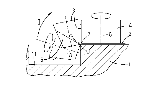
Fig. 1 is a schematic sectional view of a chuck having
a formed lamp reflector thereon of which the end rim should be
flanged.
Fig. 2 shows on a larger scale detail II of fig. 1
including schematically the means for flanging the reflector
rim.
Fig. 3-5 are sectional views corresponding to fig. 2
and illustrating alternative embodiments of the invention.
The drawing and first of all Fig. 1 shows a chuck 1
serving as exchangeable chuck in a forming machine that is not
further illustrated. A lamp reflector 2 having a circular
transverse section is formed on the chuck 1 and a rim 3 at the
open end of the reflector 2 should then be flanged outwardly
in order to serve as mounting rim for the lamp reflector, for
example.
Fig. 2-5 show four different embodiments of forming the
rim 3. The means for forming the rim 3 include in all
embodiments a support roller 4 and a forming roller 5. The
support roller 4 is rotatable about a rotation axis 6
perpendicularly intersecting the center of the chuck 1. The
circumferential edge 7 of the support roller 4 which is facing
the chuck, determines the bending line of the reflector rim 3.
The forming roller 5 consists of a truncated cone-
shaped roller which is not only rotatable about its rotation
axis 8, but which is also tiltable according to arrow I by
means of drive means not shown. The tilting axis of the
forming roller 5 is tangent to an end edge 10 of the chuck 1
determining the bending or flanging line of the end edge 3 of
the reflector 2 together with the circumferential edge 7 of
the support roller 4. The tilting movement of the forming
roller 5 may be guided by means of a guide having the shape of
a circular segment which is concentrically about the tilting
axis at the position of the end edge 10. A circumferential
groove 11 in the chuck 1 enables the placement of the forming
rollers 5 inwardly of the end edge 10 of the chuck 1.
The method of forming the reflector rim carried out by
the apparatus of Fig. 2 is as follows.
2150961
4
After forming the lamp reflector 2 about the chuck 1,
the chuck 1 is rotated about the longitudinal centerline again
while the support roller 4 is brought into the position of
fig. 2 and the support roller 4 will rotate about the rotation
axis 6 with such rotational speed that the circumferential
speed thereof will substantially correspond to the surface
speed of the reflector rim 3 to be formed. The starting
position of the forming roller 5 is shown in ghost lines in
fig.2 and in which position the rotation axis of the forming
roller 5 is parallel to or inclined at a small angle to the
longitudinal centerline of the chuck 1. The reflector rim 3
will generally be deformed slightly during the formation of
the lamp reflector, as shown in fig. 2, but that is not
important in the further process. The forming roller 5, like
the forming roller 4, is rotatable about its rotation axis 8
with such speed that the curremferential speed is
substantially equal to the surface speed of the rim 3 to be
formed. By rotating the chuck 1 together with the lamp
reflector 2 and by slowly tilting the forming roller 5 in
accordance with arrow I, the rim 3 will gradually be flanged
by deformation and will finally be rolled between the rollers
4 and 5 with the forming roller 5 in the end position
indicated by bold lines. The control of the forming roller 5
may be an open loop control based on force, that is forming
roller 5 is tilted and is forced with a predetermend force or
rolling pressure against the rim 3.
Fig. 3 shows a modification of the embodiment of fig. 2
with is particularly suited in situations in which material
compression of the reflector rim 3 should be carried out,
contrary to the embodiment of fig. 2 in which less material
compression takes place, so that the embodiment is
particularly suited for reflectors having facets and for spray
painted surfaces. The embodiment of fig.3 is better suited for
chemacally brightened or anodized reflectors. The difference
to the embodiment of fig. 2 is that the support roller 4 is
provided on the end face adjacent the chuck 1 with a short
support portion 12 having a circumferential end face 13 having
' - 21509fi1
a larger diameter than the remaining portion of the support
roller 4. As a result, the support roller abuts the reflector
rim only with a short circumferential end face 13 which is
shorter than the width of the reflector rim 3 to be formed. In
5 order to cover and roll the whole reflector rim 3 any way, the
support roller 4 is displaceable outwardly in a direction
according to arrow II parallel to the reflector rim 3, in this
case in a direction to the rotation axis 6. During
displacement of the support roller 4, the wall 3 is compressed
and finished.
Fig. 4 shows an embodiment of the invention which is
similar to fig.3, but wherein the support roller 4 can be
moved a number of times in outward direction along the end rim
3 abutting this rim 3, while this supporting roller 3 is moved
back each time spaced from the rim 3 by a lateral movement
according to arrow III. This embodiment is particularly suited
for thicker materials of the lamp reflector 2.
The embodiment of fig. 5 is intended for rims 3 which
should not be flanged perpendicularly but at a different
angle. In this case, the rim 3 is deformed beyond the
perpendicular plane, but it is also possible of course to
flange the rim 3 to a smaller angle. In this embodiment the
circumferential end face 13 is conical at the same angle as
through which the rim 3 should be flanged. The rotation axis 6
of the support roller 4 is still perpendicular to the center
line of the chuck 1, but the displacement according to arrow
II of the support roller 4 is parallel to that of the end
position of the rim 3, or at the same angle as the tangent of
the circumferential end face 13 to the rim, adjacent to the
forming roller 5, respectively. In fig.5 it is shown that the
forming roller 5 is tilted through a larger angle as with fig.
2-4.
The invention is not restricted to the embodiments
shown in the drawing and discribed hereinbefore by way of
example, which may be varied in different manners within the
scope of the invention. The invention may for example also be
used for round objects of which an end rim should be flanged.