Some of the information on this Web page has been provided by external sources. The Government of Canada is not responsible for the accuracy, reliability or currency of the information supplied by external sources. Users wishing to rely upon this information should consult directly with the source of the information. Content provided by external sources is not subject to official languages, privacy and accessibility requirements.
Any discrepancies in the text and image of the Claims and Abstract are due to differing posting times. Text of the Claims and Abstract are posted:
| (12) Patent: | (11) CA 2151321 |
|---|---|
| (54) English Title: | SEPARATING DEVICE |
| (54) French Title: | DISPOSITIF SERVANT A SEPARER LES LIQUIDES ET LES SOLIDES |
| Status: | Expired and beyond the Period of Reversal |
| (51) International Patent Classification (IPC): |
|
|---|---|
| (72) Inventors : |
|
| (73) Owners : |
|
| (71) Applicants : |
|
| (74) Agent: | SMART & BIGGAR LP |
| (74) Associate agent: | |
| (45) Issued: | 2007-02-13 |
| (22) Filed Date: | 1995-06-08 |
| (41) Open to Public Inspection: | 1995-12-10 |
| Examination requested: | 2002-06-05 |
| Availability of licence: | N/A |
| Dedicated to the Public: | N/A |
| (25) Language of filing: | English |
| Patent Cooperation Treaty (PCT): | No |
|---|
| (30) Application Priority Data: | ||||||
|---|---|---|---|---|---|---|
|
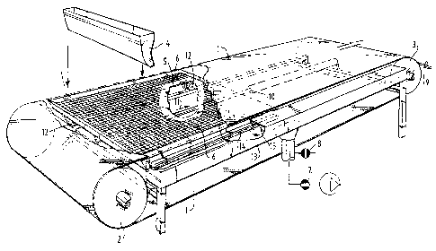
The invention relates to a device for separating
liquids and solids. An endless filter belt is used, beneath
which a suction box is placed which can generate
underpressure relative to the ambient pressure. The suction
box is bounded on at least one of the sides by a stationary
underpressure box, wherein the suction box is provided with
connecting means co-acting with the underpressure box. This
enables embodying of the connection between the suction box
and this underpressure box without for example rubber
connecting hoses. This is important because rubber material
cannot for instance withstand high temperatures.
Note: Claims are shown in the official language in which they were submitted.
Note: Descriptions are shown in the official language in which they were submitted.
2024-08-01:As part of the Next Generation Patents (NGP) transition, the Canadian Patents Database (CPD) now contains a more detailed Event History, which replicates the Event Log of our new back-office solution.
Please note that "Inactive:" events refers to events no longer in use in our new back-office solution.
For a clearer understanding of the status of the application/patent presented on this page, the site Disclaimer , as well as the definitions for Patent , Event History , Maintenance Fee and Payment History should be consulted.
| Description | Date |
|---|---|
| Time Limit for Reversal Expired | 2010-06-08 |
| Letter Sent | 2009-06-08 |
| Inactive: Office letter | 2007-04-11 |
| Inactive: Delete abandonment | 2007-04-10 |
| Inactive: Reversal of deemed expired status | 2007-04-10 |
| Grant by Issuance | 2007-02-13 |
| Inactive: Cover page published | 2007-02-12 |
| Inactive: Corrective payment - s.78.6 Act | 2007-01-29 |
| Pre-grant | 2006-11-27 |
| Inactive: Final fee received | 2006-11-27 |
| Notice of Allowance is Issued | 2006-06-20 |
| Letter Sent | 2006-06-20 |
| Notice of Allowance is Issued | 2006-06-20 |
| Inactive: Approved for allowance (AFA) | 2006-05-08 |
| Amendment Received - Voluntary Amendment | 2006-03-13 |
| Inactive: S.30(2) Rules - Examiner requisition | 2005-12-07 |
| Amendment Received - Voluntary Amendment | 2005-06-21 |
| Inactive: S.30(2) Rules - Examiner requisition | 2004-12-22 |
| Amendment Received - Voluntary Amendment | 2004-07-12 |
| Inactive: S.30(2) Rules - Examiner requisition | 2004-04-20 |
| Letter Sent | 2002-06-25 |
| Inactive: Status info is complete as of Log entry date | 2002-06-25 |
| Inactive: Application prosecuted on TS as of Log entry date | 2002-06-25 |
| Inactive: Entity size changed | 2002-06-14 |
| All Requirements for Examination Determined Compliant | 2002-06-05 |
| Request for Examination Requirements Determined Compliant | 2002-06-05 |
| Time Limit for Reversal Expired | 1998-06-08 |
| Letter Sent | 1997-08-28 |
| Deemed Abandoned - Failure to Respond to Maintenance Fee Notice | 1997-08-26 |
| Reinstatement Requirements Deemed Compliant for All Abandonment Reasons | 1997-06-25 |
| Reinstatement Requirements Deemed Compliant for All Abandonment Reasons | 1997-06-25 |
| Deemed Abandoned - Failure to Respond to Maintenance Fee Notice | 1997-06-09 |
| Application Published (Open to Public Inspection) | 1995-12-10 |
| Abandonment Date | Reason | Reinstatement Date |
|---|---|---|
| 1997-08-26 | ||
| 1997-06-09 |
The last payment was received on 2006-05-17
Note : If the full payment has not been received on or before the date indicated, a further fee may be required which may be one of the following
Please refer to the CIPO Patent Fees web page to see all current fee amounts.
| Fee Type | Anniversary Year | Due Date | Paid Date |
|---|---|---|---|
| MF (application, 2nd anniv.) - standard | 02 | 1997-06-09 | 1997-06-25 |
| Reinstatement | 1997-06-25 | ||
| MF (application, 3rd anniv.) - standard | 03 | 1998-06-08 | 1998-05-28 |
| MF (application, 4th anniv.) - standard | 04 | 1999-06-08 | 1999-06-04 |
| MF (application, 5th anniv.) - standard | 05 | 2000-06-08 | 2000-05-31 |
| MF (application, 6th anniv.) - standard | 06 | 2001-06-08 | 2001-05-31 |
| MF (application, 7th anniv.) - standard | 07 | 2002-06-10 | 2002-06-03 |
| Request for examination - standard | 2002-06-05 | ||
| MF (application, 8th anniv.) - standard | 08 | 2003-06-09 | 2003-05-29 |
| MF (application, 9th anniv.) - standard | 09 | 2004-06-08 | 2004-05-28 |
| MF (application, 10th anniv.) - standard | 10 | 2005-06-08 | 2005-05-26 |
| MF (application, 11th anniv.) - standard | 11 | 2006-06-08 | 2006-05-17 |
| Final fee - standard | 2006-11-27 | ||
| 2007-01-29 | |||
| MF (patent, 12th anniv.) - standard | 2007-06-08 | 2007-05-17 | |
| MF (patent, 13th anniv.) - standard | 2008-06-09 | 2008-05-15 |
Note: Records showing the ownership history in alphabetical order.
| Current Owners on Record |
|---|
| PANNEVIS B.V. |
| Past Owners on Record |
|---|
| ALPHONS ARNOLDUS JOHANNES ANTONIUS PRINSSEN |
| KAREL ANTOON THISSEN |

