Note: Descriptions are shown in the official language in which they were submitted.
2151450
Field of the Invention
This invention relates to a clutch/brake
mechanism for a transmission for washing machines and, more
particularly in the preferred embodiment, top loading
washing machines.
Background of the Invention
Washing machines have a transmission located
immediately adjacent the tub. Typically, these
transmissions produce a back and forth agitating movement
of an agitator for rotation of the washing machines motor
in one direction, with a continuous direct spin of the tub
being produced upon the rotation of the motor in an
opposite direction. The transmission thus provides a dual
state operation depending upon the direction of rotation of
the motor for the machine. The status of the transmission
is dependent on some sort of motor rotation direction
sensitive clutch/brake mechanism. Typically, these
transmissions are relatively large and heavy designs having
cast iron housings and complicated interconnections between
parts in order to provide for the agitation movement. The
Franklin and Whirlpool units are typical of these designs.
Objects and Summary of the Invention
It is an object of the present invention to
provide for a low cost clutch/brake mechanism for a
transmission.
It is another object of the present invention to
simplify the construction of transmissions.
It is yet another object of the present invention
't~
2151450
- 2 -
to lower the physical size of a clutch/brake mechanism for
transmissions.
It is still another object of the present
invention to reduce the weight of transmissions.
It is a further object of the present invention
to lower to cost and size of the associated washing
machine.
Other objects and a more complete understanding
of the invention may be had by referring to the drawings in
which:
Brief Description of the Drawings
The structure, operation, and advantages of the
presently disclosed preferred embodiment of the invention
will become apparent when consideration of the following
description taken in conjunction with the accompanying
drawings wherein:
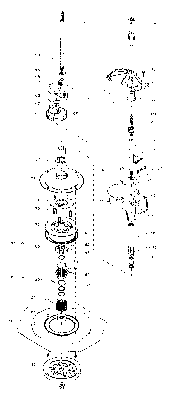
FIGURE 1 is a perspective view of a disassembled
transmission incorporating the invention of the
application;
FIGURE 2 is a longitudinal cross section view of
the assembled transmission of figure 1;
FIGURE 3 is an actual size top view of the
actuation member for the clutch/brake mechanism;
FIGURE 4 is a cross sectional view of the
actuation member of figure 3 taken along lines 4-4;
FIGURE 5 is an actual size bottom view of the
reaction member for the clutch/brake mechanism;
2151450
- 3 -
FIGURE 6 is a cross sectional view of the
reaction member of figure 5 taken along lines 5-5;
FIGURE 7 is an enlarged view of one of the ramp
pockets of the actuation member;
FIGURE 8 is an enlarged cross sectional side view
of the ramp pockets of figure 7 taken generally along the
arc 8-8;
FIGURE 9 is an enlarged perspective view of the
activation and reaction members of figure 1;
FIGURE 10 is a lateral cross sectional view of
the transmission taken substantially along lines 10-10 in
figure 2; and,
FIGURE 11 is a second lateral cross sectional
view of the transmission taken substantially along lines
11-11 in figure 2 without counterweight.
Detailed Description of the Invention
The clutch/brake mechanism of this invention is
designed for preferable use with a transmission for a
washing machine. The washing machine includes a motor
agitator and a tub. These are found in representational
form in figure 2 as items 8 and 7, respectively.
The motor 8 is capable of bidirectional rotation,
the direction of rotation depending upon the allied washing
machine control system in the customary manner. Upon
rotation of this motor 8 in one direction, the transmission
produces back and forth angular agitation of the agitator 7
with rotation of the motor 8 in the opposite direction
causing spinning of the tub 9. This dual control action is
produced by the transmission for the washing machine; and
in the preferred embodiment disclosed the clutch/brake
2151450
- 4 -
mechanism that activates the transmission. Some motors
also provide variable speeds in addition to directional
control so as to vary the duty cycle. Again, this duty
cycle is under the control of the allied washing machine
control system.
The transmission 10 includes a housing 20, an
agitation system 60, and an activating system 80. The
activating system 80 includes the clutch/brake mechanism of
this invention.
The housing 20 serves to contain the physical
elements of the transmission. The preferred housing
disclosed includes a lower housing 21 and an upper housing
22. The lower housing 21 is a deep drawn casting,
preferably a low density material such as aluminum, having
a cavity 25 sufficient to contain the physical parts of the
transmission. The lower housing 21 in addition preferably
includes an integral longitudinal extension 26 on the
opposite side of the cavity 25 to provide an extended
bearing support. The lower housing 21 also includes a
sideways extending lateral cutout 27 for localizing the
counterweight (later described). An input tube 30 fixedly
connected or integral to the extension 26 provides an
interconnection between the frame 100 of the washing
machine, the housing 20 and later described clutch system
60. Two bearings 31 are included on the inside of the
input tube 30 for rotatively supporting the later described
input shaft 35.
A high mass counterweight 32 is located in the
cutout 27 with rubber isolator 33 retaining the
counterweight 32 in location. This counterweight 32 is
designed to counter balance the otherwise uncompensated for
parts of the housing 20 and agitation system 60 (for
example the eccentric gear 61). Without this counterweight
32, a vast increase in size and complexity of design for
the other parts of the transmission 10 would be necessary
.:. 2151450
- 5 -
to provide for a smooth balanced spinning of the wash tub
9.
In the preferred embodiment disclosed, the lower
casing 21 is also made of a low density material, aluminum,
while the counterweight 32 is made of a higher density
material, steel. This allows for a more effective use the
mass of the counterweight 32 than would be possible with
similar density materials. Also, the location of the
center of mass of the counterweight 32 is preferably at a
significant distance greater than the compensated for parts
from the rotational axis of the transmission 10 further
increases its effectiveness regarding lesser distances. In
this respect, also note that in the preferred embodiment
the center of mass of the counterweight 32 is located
approximately 50% further outward from the rotational axis
of the transmission than the center of mass of the furthest
item out needing compensation (the gear 61 which has its
center of mass substantially coextensive with the shaft
66). This further increases the effectiveness of the
counterweight.
The input shaft 35 is rotatively mounted in
respect to the lower housing 21 by the bearings 31. This
input shaft 35 is axially in line with the later described
agitator shaft 63. This simplifies and strengthens the
support of the housing 20 to the frame of the washing
machine as well as allied drive parts including the tub 9.
A ball 38 between the upper end of the input
shaft 35 and the lower end of the agitator shaft 63 locates
both such shafts axially in position as well as providing
for a thrust bearing for the later described agitator. As
the ball 38 rotates and spins during the operation of the
device, wear is spread out evenly over the full outer
surface of such ball 38.
A pulley 36 is fixedly connected to the lower end
-- 2151450
- 6 -
of the input shaft 35 for supplying power between the motor
8 and the input shaft 35. The sizing of this pulley allows
for a reduction in relative speed between the motor and the
input shaft 35. An input pinion 37 is splined on the other
end of the input shaft 35 for drivingly connecting the
input shaft 35 with the later described eccentric gear 61.
The upper housing 22 completes the housing 20.
The upper housing 22 consists of a low profile closure
member 40 and an agitator tube 41. When the upper housing
22 is bolted to the lower housing 21 by bolts 42 with the
seal 43 therebetween, the housing is complete. Two
additional bearings 44 rotatively support the later
described agitator shaft 63 in the agitator tube 41 of the
upper housing 22. Again, the upper housing 22 is
preferably made of a low density material such as aluminum
so as to increase the effectiveness of the counterweight
32. As the agitation shaft 63 is in line with the input
shaft 35, any inherent rotary imbalance is eliminated. The
careful design techniques, for example the counterweight
32, further reduce any imbalance.
The agitation system 60 is the mechanism which
alters the constant unidirectional rotation of the pulley
36 into a differing direction, a back and forth movement,
of the cleansing agitator 7 in the tub 9, thus providing
the necessary cleansing movement for the clothes therein.
The preferred agitation system disclosed includes an
eccentric gear 61, an agitator rack 62, and an agitator
shaf t 63 .
The eccentric gear 61 is rotatively mounted to
the housing 20 by an idler shaft 66 which is located
extending between holes in the lower housing 21 and the
upper housing 22. The eccentric gear 61 shown is directly
rotated by the input pinion 37 which extends off of the end
of the input shaft 35. The particular input pinion 37
eccentric gear 61 gear ratio has an approximate four to one
2151450
_ 7 _
reduction, a reduction significantly lower than customary
in washing machine transmissions.
A bearing piece 67 extends off of one side of the
eccentric gear 61. The center of this bearing piece 67 is
displaced from the center of the eccentric gear 61. The
side of the bearing piece 67 has a hole 69 through it and
the rest of the axial depth of the eccentric gear 61 in
order to reduce side to side imbalance forces during
rotation (later described). A raised pie shaped section 68
off of the top of the eccentric gear 61 also aids in
reducing this imbalance.
The agitator rack 62 has a circular bearing 70
and a cavity with teeth 71 (see figure 10). The circular
bearing 70 of the agitator rack 62 is located around the
bearing piece 67 of the eccentric gear 61 with the toothed
head 64 of the agitator shaft 63 in driving contact with
the teeth 71 of the rack 62. The cavity with teeth 71 is
laterally offset in respect to the circular bearing 70.
This reduces vibration by locating the longitudinal power
transferring axis of the rack of teeth 71 in line with the
central rotational axis of the circular bearing 70 (and
shaft 66). This is preferred. A small bearing pad 65
extends between the non-toothed section of the head 64 of
the agitator shaft 63 so as to bear on the flat surface 74
of the cavity in the rack 62 on the opposite side as the
teeth 71. This bearing pad 65 has longitudinal slots
(dotted lines 73 in figure 9) molded into the bottom
thereof in order to provide for uniform wall thickness and
thus improve cooling. The bearing pad further has a slight
lip 75 formed extending off of the top thereof. This lip
75 cooperates with a small groove 72 formed in the top
surface of the rack 62 to support the bearing pad 65 in
position. Other means such as a groove in the toothed end
of the agitator shaft with corresponding lip for the
bearing piece 65, a washer above pinion 37, etc. could also
be used to hold this bearing pad 65 in axial position.
.: 2151450
_8_
The agitator shaft 63 itself is supported by
bearings 44 to the agitator tube 41 of the housing 20. The
longitudinal rotational axis of the agitator shaft 63 is in
line with the longitudinal rotational axis of the input
shaft 35. This allows the use of a simple ball thrust
bearing ball 38 as well as simplifying the construction of
the remainder of the washing machine.
During agitation, the housing 20 is fixedly
connected to the frame of the washing machine (by the later
described disc brake assembly 90). This forces the input
shaft 35 to rotate in respect to the housing 20. This in
turn causes the eccentric gear 61 to rotate. As the
eccentric bearing piece 67 has a central rotational axis
offset from that of the eccentric gear 61, any rotation of
the eccentric gear 61 causes the agitator rack 62 to move
back and forth with a reciprocating reversing movement for
a limited longitudinal extent. As the teeth 71 of the rack
62 are in driving engagement with the toothed head 64 of
the agitator shaft 63, this mechanism translates the pure
rotation of the input shaft 35 into a back and forth
limited reversing rotational movement of the agitator shaft
63 (about 110° in the embodiment shown). This
transformation is facilitated by the use of the bearing pad
65 between the toothed head 64 and the flat surface 74 of
the rack. The reason for this is that the bearing pad 65
spreads out the force from the toothed head 64 over a
larger surface than otherwise possible (without the bearing
pad 65, there would be direct linear contact between the
toothed head 64 and the flat surface 74, thus concentrating
the forces in a very small area). This increases wear and
reduces durability of the transmission. The bearing pad 65
reduces friction and wear between the agitator rack 62 and
the agitator shaft 63.
Due to the use of the preferred design, the
amount of mass shifting in the transmission 10 is reduced
relative to other systems. For example as explained and as
2151450
_ g _
can be seen in figure 9, most of the side to side shifting
is caused by the bearing piece 67 of the eccentric gear 61
and the circular bearing 70 of the agitator rack. Due to
the hole 69 in the bearing piece 67 and the narrow width of
the circular bearing 70, the effective mass of both of
these parts are minimized. This in combination with the
high effectiveness of the mass of the counterweight 32 and
the pie shaped raised section 68 of the eccentric gear 61
(as previously described) reduces off balance rotation.
This is particularly so when one considers the effective
mass of the damp clothes in the washing tub during any spin
cycle. The designed in parameters thus lowers vibration
relative to competitive designs.
The operative condition, agitation, or rotation
of the transmission 10 is produced by an activating system
80. This activating system 80 includes a means of tying
the input pulley 36 directly to the housing 20 so as to
transfer 100% of the rotation of the pulley 36 to such
housing 20. This causes spinning of the tub 9. A means to
interconnect the housing 20 to the fixed relatively
immovable position frame 100 of the washing machine is also
included so as to lock the housing 20 into position in
respect thereto. This activates agitation by providing a
reaction lock for the agitation system. As later
described, the selective operation of one or the other of
these means produces the two operative conditions for the
transmission 10. The selective operation is controlled by
the clutch/brake mechanism invention of this application.
In the unpowered condition of the transmission
10, the default condition is the fixing of the housing 20
to the frame 100 of the washing machine by the later
described brake assembly 90. (This condition is produced
by the force of three springs 93 acting downwardly on a
brake disc 91 so as to engage it with a brake surface 92 of
the frame 100.) This operative condition of the
transmission 10 remains in effect on rotation of the pulley
2151450
- 10 -
36 into an agitation direction. At this time, the brake
assembly 90 provides a reaction member for the agitation.
On rotation of the pulley 36 in a spin direction,
the brake assembly 90 is released and the housing 20 tied
to the pulley 36 for common rotation. This operative
condition of the transmission 10 remains in effect on
continuation of rotation of the pulley 36 in a spin
direction, reverting to a default condition on cessation of
such rotation.
In the embodiment disclosed in figure 1, the two
conditions are provided by an inclined ramp clutch assembly
81 and a large disc brake 90. The particular clutch
assembly 81 disclosed provides for the rotation connection
as well as deactivating the disc brake. It thus is part of
both means.
The inclined ramp clutch assembly 81 includes an
actuation member 82, a reaction member 85, a pulley hub 88,
and a clutch spring 87.
The pulley hub 88 is fixedly connected to the
input pulley 36 for rotation therewith in either direction.
This pulley hub 88 shown is a generally cylindrical member
some 2/3" high and 1+1/2" in diameter connected by a lower
star shaped protrusion to the pulley 36. This pulley hub
88 has, at its outer circumference, a unidirectional spiral
wound clutch spring 87 surrounding it. This clutch spring
87 is spiral wound so as to allow free rotation of the
pulley hub 88 in one direction of rotation while locking
the pulley hub 88 to the actuation member 82 for rotation
therewith on rotation in the other direction. The
particular clutch spring 87 is left hand close wound of
1/16" wide substantially square wire having an inner
diameter very slightly less (1/100) than the 1+1/2"
diameter of the pulley hub 88. There are some 18 coils in
a stack 1+1/4" high.
. 2151450
- 11 -
A small thrust bearing 115 some 1+1/4" in
diameter is located between the actuation member 82 and the
pulley hub 88. This bearing 115 facilitates the later
described relative 35° actuation rotation between these two
parts. The particular bearing 115 disclosed includes one
race 116 formed integrally with the actuation member 82, a
ball retainer 117, and a separate lower ball raceway 118.
A retaining ring 119 maintains the parts in position so as
to complete the bearing.
The actuation member 82 shown is substantially
cylindrical in shape having an outer diameter and height
substantially matching that of the pulley hub 88 (1+1/2"
and 2/3" respectively). The aggregate height of the
actuation member 82 and the pulley hub 88 substantially
matches that of the clutch spring 87.
The actuation member 82 includes on its upper
surface a number of inclined ramp pockets 86 (six shown).
It is preferred that there be from three to nine pockets in
order to reduce the compressive and actuation forces on
each individual pocket and contained ball. In general, the
smaller or more damageable the balls, the greater the
number of pockets. With the embodiment herein set forth
having a design envelope of a 35° actuation movement, six
pockets and 1/4" balls are utilized. An upper flange some
2" in diameter and 1/4" thick provides for a location for
the inclined ramp pockets 86. Each of these ramp pockets
86 allow for slightly over 1/2" of ball travel with an
initial angle of substantially 9° and thereafter
continually less for most of the ramps length with the
upper end of the ramp being angledTat substantially 3°.
This ramp pocket is curved at about a 4.25" or 4.67"
radius. This curved ramp design is preferred due to its
even compensation for the change in spring compression
rates during activation. The 3° top angle encourages the
ball to roll down the ramp when the motor 8 is stopped.
Alternately the ramp pockets 86 might be angled, for
2151450
- 12 -
example, a constant 6° along the ramp length. The ramps
each extend some 35° about the circumference of the
actuation member 82. The total depth of the ramp pocket 86
is slightly less (.010) than the radius of the later
described actuation balls 84. The tabs 83 extend some 1/8"
outwards of the upper flange of the actuation member, each
for some 20° about the actuation member 82.
The reaction member 85 is located immediately
above the actuation member 82. The reaction member 85
includes inward projections 111 that fit into corresponding
grooves 112 on the outer circumference of the tube 30 of
the lower housing 21 to fixedly tie the same together for
common rotation. The pockets 87 inverse to those in the
agitation member 82 are formed in the lower surface of the
reaction member 85 (i.e., reversed 180° in profile). Note
that it is preferred that again both these ramp pockets
have a reduced (or even flat) incline at their shallowest
ends. The reason for this is while the initial spin torque
might be high (50 pounds for example), the continuing spin
torque can be a fraction of this (ten pounds for example).
As in the preferred embodiment disclosed, there is a
substantially 180 pound spring force from the disc brake
springs 93, the use of the reduction in incline is utilized
to maintain the brake in deactivated condition even during
a severe torque drop as long as the pulley 36 continues to
be rotated by the motor in a spin direction. In addition,
the reduction in incline also aids to prevent stuttering
when there are torque load variations at a given level
(unbalanced loads for example).
The reaction member 85 shown is a generally
disklike member some 2" in diameter and 1/2" thick. There
are three inclined ramp pockets 87 in the lower surface of
the reaction member 85. These pockets 87 are inverse image
to those pockets 86 in the actuation member 82 (fig 5).
Three tabs 95 are located extending downwardly some 1/8"
off of the outer edge of the reaction member 85 for some
2151450
- 13 -
20° about the reaction member 85. These tabs 95 and the
tabs 83 of the actuation member 82 are located in respect
to each other such that when in contact, the resting spot
for the actuation balls 84 is somewhere on the 3° surface.
The pockets 89 and a circumferential support groove are
located on the upper surface of the reaction member 85.
The pockets 89 interact with matching inwardly extending
teeth on the disc brake 91 so as to tie the two parts
rotatively together. The support groove allows the inner
part of such disc 91 to overlay the reaction member 85,
thus strengthening this interconnection in respect to axial
forces therebetween.
The actuation balls 84 are captured between the
ramp of the actuation member 82 and the pockets of the
reaction member 85. It is preferred that these actuation
balls be made of brass. The reason for this is to avoid
fretting or indentations that might cause the brakes to
hang up. Alternately, other resilient materials may be
used, for example, plastics, orlon, or nylon. These balls
84 act to physically separate the actuation member 82 from
the reaction member 85 on the relative rotation
therebetween in one certain direction. These actuation
balls are some 1/4~~ in diameter.
The set of overlapping tabs 95, 83 respectively
extending off of the edges of the reaction member 85 and
actuation member 82 respectively are designed to solidly
drivingly interconnect the actuation member 82 to the
reaction member 85 at or slightly before the balls 84
contact the shallow end of the ramp pockets 86 while such
balls 84 are located on the 3° surface.
With this orientation, relative rotation between
the actuation member 82 and reaction member 85 in one
direction moves the reaction member 85 first upwards (via
the clutch spring 87 and the balls 84 against the springs
93) for the first 35° and then ties the reaction member 85
2151450
- 14 -
to the actuation member 82 (via the tabs 95-83) for
rotation therewith. As the reaction member 85 is in turn
solidly connected to the housing 20 (via its toothed inner
surface to the lower end of the tube 30 of the lower
housing), this rotation of the reaction member 85 also
serves to tie the pulley 36 to the housing 20 for common
rotation (i.e., spin cycle).
The disc brake 91 is deactivated by the upwards
movement of the reaction member 85. The reason for this is
the reaction member 85 is fixedly interconnected to the
disc 91 of the disc brake assembly for common upwards
movement; this by the top of the toothed outer surface 89
pushing against member 98. Thus the brake is deactivated
as the actuation member 82 rotates in respect to the
reaction member 85 and pushes the same upwards.
As rotation of the operative actuation member 82
is provided by the clutch spring 87 interconnection to the
pulley hub 88 caused by rotation of the pulley 36 in one
direction, the operative condition of the inclined ramp
clutch assembly 81 is dependent on the direction of
rotation of the motor 8.
The activation of the disc brake 91 serves as the
means to cause agitation to occur. This will occur if the
motor 8 revolves in an agitation direction. The reason for
this is the operation of the disc brake assembly 90.
The disc brake assembly 90 disclosed includes a
brake disc 91, a brake ring 92, a spring 93, and a reaction
member 94.
The brake disc 91 itself is a flat circular
member having a brake surface at its outer lower edge. The
inside opening of this brake disc 91 is, as previously
discussed, interengaged with the toothed outer surface of
the reaction member 85 (through part 98) so as to lock the
215145
- 15 -
brake disc 91 to tie such disc 91 to such member 85 for
rotation and upward motion therewith.
The brake disc 91 shown is some 5+1/2" in
diameter with a 2/3" wide band of brake material on the
outer circumference thereof. The inwardly extending tabs
are three in number, each substantially 1/2" wide and 3/8"
long. The central opening is approximately 2" in diameter.
A support member 94 extends between the lower
part of the housing 20 to a location adjacent to the upper
surface of the brake disc 91. This support member is
substantially 4" in diameter with a 1" inner opening. This
support member presses upwards against the inner race of
the lower main bearing 97 with the spring 93 extending
between the support member and the brake disc 91 to bias
same into braking condition with the frame via the springs
93 between the brake disc 91 and the support member 94.
These springs 93 serve to bias the brake disc 91 into an
actuated or braked position against the brake ring 92 (180
pounds spring force in the disclosed embodiment). The
springs 93 also serve to physically locate the support
member in position relative to the brake disc 91. The
spring 93 each are about 1" long and 1/2" in diameter with
coils of 1/10" thick wire. The brake ring 92 is itself
fixedly connected to the stationary frame 100 of the
washing machine. The brake ring 92 itself has a diameter
and width substantially the same as the brake material on
the brake disc 91.
As the brake disc 91 is fixedly connected to the
housing 20 for rotation therewith in its spring loaded
default condition, this serves to lock the washing machine
tub (via a disc 91) into a default braked condition
preventing the rotation thereof. This activates the
agitation mechanism of the transmission.
The inside of the brake disc 91 is positioned
--_ 2151450
- 16 -
next to the upper surface of the reaction member 85 such
that upward movement of this reaction member 85 causes the
brake disc 91 to move upwards against the force of the
spring 93 and thus release the brake.
In the embodiment shown, the disc brake assembly
90 is located adjacent to the main lower bearing support
96, a fixed part of the washing machine frame, immediately
adjacent to the main lower bearing 97. This lower bearing
support is a generally conical member having an inset
portion to hold the main lower bearing 97. The member has
a diameter of 7+1/2~~ and a height of 1+1/4~~ with a 2~~
diameter inset portion. This member is fixedly connected
to the frame of the washing machine, completely enclosing
the clutch/brake mechanism of this invention. This
enclosure protects the clutch/brake mechanism from water
leaks, dust, and other physical contaminants.
The ramp assembly 86 and brake assembly 90 are
activated by the direction of rotation of the input shaft
35.
Upon rotation of the input shaft 35 and the
pulley hub 36 in one direction, the clutch spring 87 is not
activated and the actuation balls 84 are located and remain
at the lower ends of their ramps in the actuation member 82
and their reaction member 85. This allows the disc brake
91 to continue to contact the brake ring 92, thus holding
the lower housing 21 in a position of non-rotation. This
provides a reaction member for the previously described
agitation system.
On rotation of the input shaft 35 and the pulley
hub 36 in the opposite direction, the clutch spring 87 is
activated tying the actuation member 82 to the pulley hub
36 for common rotation. This in turn forces the actuation
balls 84 to be moved to the upper ends of their respective
ramps in the actuation member 82 and the reaction member
215145
- 17 -
85. This causes the reaction member 85 to move in an
upwards direction. As the brake disc 91 is located
immediately adjacent to the upper surface 95 of the
reaction member 85, this movement also forces the disc
brake 91 upwards against the force of the springs 93 to
move away from the brake ring 92. This releases the brake.
When the tabs 83, 95 subsequently contact, the tabs serve
to tie the actuation member 82 to the reaction member 85
for rotation therewith. This in turn ties the input shaft
35 to the housing 20 for rotation therewith causing
spinning of the tub. Therefore, as long as the pulley 36
(and the shaft 35) continue to rotate in a single
direction, the tub 9 continues to rotate with the shaft.
This continues spinning of the tub 9.
On cessation of rotation of the input shaft 35,
the activation mechanism reverts to its default braked
condition. This is facilitated by the inertial qualities
of the rapidly spinning tub 9 which causes the reaction
member 85 to move faster than the actuation member 82,
forcing the balls 84 downwards to the low ends of their
ramps thus reactivating the brake 90. The 3° initial
incline of the respective pockets facilitates this return
to braking condition.
Upon resetting of the brake to its default
condition, rotation of the shaft in the first direction
will cause agitation of the agitator 7, with reverse
rotation again spinning the tub 9.
Modification of this agitation/spin activation
system are possible. For example,Tthe two operative
conditions are provided by a relative clutch and a relative
brake with the activation occurring depending on the
direction of rotation of the pulley 36 in one direction
activating the clutch with rotation in a second direction
actuating the brake. Other means of accomplishing this
could be provided.
2151450
- 18 -
Although the invention has been described in its
preferred embodiment with a certain degree of
particularity, it is to be understood that numerous changes
can be made without deviating from the invention as
hereinafter claimed.