Note: Descriptions are shown in the official language in which they were submitted.
~ 2151~93
_ WOg4/13880 - PCTISE92/00862
APPARATUS FOR FILTERING SUSPENSIONS
The present invention relates to an apparatus for filtering
suspensions, such as fibre pulp suspensions.
Wo 91/12063 discloses an apparatus for filtering
suspensions, such as fibre pulp suspensions, including
a container for the suspension to be filtered, inlet means
for supplying the suspension to the container, at least one
annular, substantially vertical disc arranged in the
container, wall means connected to the disc and forming a
filtrate chamber at the centre of the disc,and means for
rotating the disc about a horizontal axis extending
centrally through the disc. There are means dividing the
disc into a number of segments disposed in series around
the disc. Two side walls of filter material cover the disc
at mutual sides thereof,each segment and said side walls of
filter material defining a cell for receiving filtrate.
Each cell communicates with the filtrate chamber. Means is
provided for controlling the volume of the suspension in
the container during operation, such that said side walls
of filter material are partly above the suspension in the
container, while the filtrate chamber is at least partly
submerged in the suspension in the container, whereby a
fine fraction of the suspension is forced through the
filter material into the cells and further into the
filtrate chamber, and a course fraction of the suspension
is created outside the filter disc.There is means for
maintaining a pool of fine fraction in the filtrate
chamber. Fine fraction discharge means is provided for
discharging said fine fraction of the suspension from the
~ filtrate chamber, and course fraction discharge means is
provided for discharging said course fraction of the
suspension from the apparatus.
WO 94/13880 PCT/SE92100862
21~15 9 3
In this prior art filtering apparatus each cell functions
as a dropleg at the ascending part of the rotating disc,
when at least a part of the cell is above the pool of fine
S fraction in the filtrate chamber, so that a negative
pressure is created in the cell. Thus, the pressure
difference between the outside and the inside of the cell
is increased by said created negative pressure in the cell.
The increased pressure difference gives the advantages that
the flow of fine fraction through the filter material
covering the cell is increased, and a compressed mat of
particles (mainly course particles) can be formed on said
filter material resulting in an increased particle
concentration of the course fraction of the suspension.
'5
Furthermore, the prior art apparatus can be operated such
that each cell contains a volume of fine fraction, when at
least a part of the cell has been displaced up above the
suspension in the container, while the outlet of the cell
still opens into the pool of fine fraction. The advantage
of this is that fine fraction is also sucked from the mat
of particles which covers the filter material of the cell
above the suspension, whereby the particle concentration of
the course fraction is further increased.
However, the capability of the prior art apparatus for
producing a concentrated course fraction primarily depends
on the height of the column of fine fraction in each cell,
i.e. the height of the suction leg, as seen at the ascend-
ing part of the disc. Thus, the higher column of fine
raction there is trapped in the cells, the more con-
centrated course fraction can be obtained. The prior art
apparatus is deficient in this respect, because during
,otation of the disc the fine fra-tion trapped in each
_ WOg4/~0 2 1 5 1 5 9 3 PCTISE92/~862
ascending cell has to escape through the outlet of the cell
before the cell descends back into the suspension, so that
the created mat of particles on the side walls of the cell
is not rewetted with fine fraction. In consequence, the
outlet of the cell has to be large enough to allow a
sufficient flow of fine fraction from the cell. This limits
the radial extension of the cell, and as a result the
column of fine fraction in the cell is limited. The radial
extension of the cells cannot be increased by simply
increasing the diameter of the disc, because for practical
reasons (such as enabling shipment of the apparatus on
trucks) the diameter of the disc should not exceed about
3.5 metres.
The object of the present invention is to provide an
improved filtering apparatus of the type discussed above,
which does not suffer from the above-mentioned deficiences
o' the prior art apparatus.
This ob ~ct is fulfilled by a filtering apparatus of the
prior art type defined above, which is characterised in
that the cells communicate with the filtrate chamber via
respective accumulation chambers formed by further wall
means extending in the filtrate chamber, each accumulation
chamber extending axially past the disc and having an
outlet into the filtrate chamber also extending axially
past the disc.
The provision of accumulation chambers with outlets
3~ extending axially past the disc enables said outlets to be
dimensioned for the required flow of fine fraction from the
cells, even if said outlets are positioned relatively close
to the centre o' the disc. The advantage of this is that
the height o' the column of fine fraction trapped in the
cells can be considerably increased, as compared to the
W094/~0 ~ 1 S 1 S 9 3 PCT/SE92l~862 _
prior art apparatus.
Said further wall means can be arranged such that each cell
is at least partly above said pool of fine fraction at some
point of revolution of the disc at the ascending part of
the disc, while the outlet of the accumulation chamber
associated to the cell opens into said pool of fine
fraction. The advantage of this is that the negative
pressure in a cell being at said point of revolution cannot
be reduced by air entering the associated accumulation
chamber from the filtrate chamber. Said further wall means
car. alsc be arranged such that each cell is at least partly
above the suspension in the container at some point of
revolution, while the outlet of the accumulation chamber
opens into said pool of fine fraction, so that the negative
pressure in the cell is maintained at least for a while
when filtrate is sucked from the mat on the cell above the
suspension.
The outlet of each accumulation chamber is preferably
displaced backwardly in the direction of rotation of the
disc in relationship to the cell associated to the
accumulation chamber. As a result, the height of the column
of fine fraction in the cell and the corresponding
negative pressure prevailins in the cell can be increased.
In practice, the apparatus of the invention usually include
a plurality of discs. In this case, the cells of the discs
preferably form rows of cells extending in parallel with
3~ said horizontal axis, and the cells of each said row of
cells communicate with an accumulation chamber extending
axially past the discs and having an outlet also extendins
past the discs.
3~ The invention is explained below in more detail by way of
2151~3
_ W094/~0 ~ ' PCT/SE92/~862
example with reference to the accompanying drawings, in
which
Figure 1 is a vertical cross-section of an embodiment of
the filterins apparatus of the invention,
- 5 Figure 2 is a longitudinal cross-section taken along line
II-II of Figure 1,
Figure 3 is a part of a sectional view along line III-II'
of Figure 2,
Fisule 4 is a section along line IV-IV of Figure 3,
Figure 5 is a part of a sectional view along line V-V of
~igu.e 3,
Figure 6 is a modification of the embodiment shown ir.
~igure 5,
Figure 7 is an enlarged part of a sectional view along line
V.I-VII of Figure 1,
Figure 8 is a sectional view along line VIII-VIII of
Figure 3,
Figure 9 is a modification of the embodiment shown in
Figure 3,
Fisure 10 is a view along line X-X of Figure 9,
Figure 1' is a partial view along line XI-XI of Figure S,
Figure 1~ is another modification of the embodiment shown
in Figure 3,
Figure 13 is a sectional view along line XIII-XIII of
Figure 12, and
Figure 14 is a detail of the embodiment shown in Figure 12.
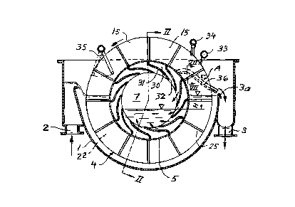
The filtering apparatus shown in Figs.l and 2 comprises a
container 1 with an inlet 2 for the suspension to be
filtered at one side of the container 1, and an outlet 3
for thickened suspension, i.e. created course fraction, at
the opposite side of the container 1. A member 3a for
cont.ollins the volume of the suspension in the container 1
is arranged at the outlet 3. In the container 1 there are
3~ fou- annular discs 4 spaced .rom one another and arranged
W094/L3880 2151S93 PCT/SE92/00862 _
transve.sely to a horizontal axis, which extends centrally
through the discs 4 The radially inner ends of the annular
discs 4 a.e sealingly attached to circular cylindrical wall
portions 5, wh,ch form a hollow shaft 6, the interior of
which constitutes a filtrate chamber 7
The shaft 6 is journalled on the container 1 by means of two
bearings 8 and 9 A drive motor 10 is connected to a gable
wall 11 at one end of the shaft 6 for rotating the shaft 6
and the discs 4 about said horizontal axis Opposite the
gable wall 11, the hollow shaft 6 has an open end, at which
one of the cylindrical wall portions 5 seals agalnst the
container ' via a sealing ring 12 The filtrate chamber 7
communicates via said open end o. the shaft 6 with a fine
fraction outlet 13 The container 1 has an adjustable
overflow membe, 13a for providing a pool of fine fraction
in the filtrate chamber 7
Each disc 4 is divided by twelve partition wall members 14
2G into twelve segments 15 disposed in series around the disc
4 Each segment 15 comprises a double-walled support member
16 having radially extending ridges 17, and a frame
consisting of two U-profiled side beams 18, 19 and a U-
profiled radially outer end beam 20, which are applied on
the side edges of the support member 16 The side beams 18,
lS are welded to the partition wall members 14
Each disc 4 is at both sides covered with side walls 21 of
flexible filter material, such as cloth, the side walls 21
being supported by ~he .idges 17 A cell 22 for receiving
filtrate is defined by each segment 15 and the side walls
2' of filter material coverins the segment 15 The discs 4
are posit.oned such that the cells 22 of the discs 4 form
;-ows o' cells 22 extending in parallel with said horizon'al
~5 axis
_ wo ~/~o 21~15 9 3 PCT/SE92/~862
~n Fig.5, the reference numeral 23 indicates a device for
radially stretching the side walls 21 of filter material
against the wall portions 5. In Fig.8 there is shown a
device for circumferentially stretching the side walls 21
of filter material alons the disc 4, comprising radially
extending pairs of pipes 24, 25, which are located between
the segments 15 at the outside of the side walls 21, and
draw bars 26 connecting the pipes 24, 25 of each pair, for
drawing the pipes 24,25 towards one another, so that the
side wa'ls 21 of filter material are stretched.
As an alternative, the cylindrical wall portions 5 can be
replaced by a single cylindrical drum 27 provided with
holes 28 for the respective cells 22 (Fig.6). In this case,
each f,lte. segment 15 may be clamped to the drum 27 as a
separate unit by means of clamping bars (not shown), the
segmen' 15 being radially sealed to the drum 27 via a
sealing ring 29.
The cells 22 of each said row of cells communicate with the
filtrate chamber 7 via an accumulation chamber 30 formed b~
wall members 31 in the filtrate chamber 7. Each accumu-
lation chamber 30 extends axially along the entire filtrate
chamber 7 and has an outlet 32 into the filtrate chamber 7
also extending axially along the entire filtrate chamber 7.
In the circumferential direction of the discs 4 the wall
members 31 extend from the segments 15 backwardly in the
direction of rotation of the discs 4. In conseguence, the
3C outlet 32 of each accumulation chamber 30 is circum-
ferentially displaced backwardly in the direction of
rotation in rela'ionship to the cells 22 Oc the row of
cells associated to the accumulation _hamber 30.
3~ At the ascending part o' each disc 4 above the suspension
WOg4/~ PCT/SEg2/OU~2--
21S1593
there are two consecutive spray nozzles 33, 34 at each side
o the disc 4, fo. providing the removal of created mats of
particles from the disc 4. At the descending part of the
disc 4 above the suspension there is an oscillating spray
nozzle 35 at each side of the disc 4, for cleansing the
side walls 2' of filter material.
Between adjacent discs 4 there are entrainment members 36
at'ached to the discs 4 for rotation therewith. Each
entrainment member 36 is U-profiled and has a limited
extension axially from the disc 4, in o.der to avoid
ir.terference with the oscillating spray nozzle 3', as the
er.trainment member 36 passes the latter during rotation of
the disc 4 (Fig.7).
Ar. impo~tant field of use of the apparatus of the invention
is fo dewatering fibre pulp suspensions and, therefore,
the operation o, the apparatus shown in Figs. 1 to 8 will
be described in the following in connection with dewaterins~
of a fibre pulp suspension.
A fibre pulp suspension to be dewatered having a fibre
concentration of typically 0.6 % is supplied to the
container 1 through the inlet 2, so that the side walls 21
cf f_lte- material which cover some of the segments 15 a'
the top of the discs 4, are above the suspension. The shaft
6 is rotated by the drive motor 10 in a direction, such
that the segments 15 which are located next to the inlet 2
for the suspension to be filtered are displaced downwa,da,
while the segments 15 which are located next to the course
f.actior. outlet 3 are displaced upwards. The hydrostatic
pressure in the suspension ir, the container 1 causes a fine
fraction Gf the suspension, mainly containing water, to
pass through the side walls 21 of filter material into the
cells 22. The fine fraction so created flows from the cells
2151593
- WO94/L~0 ~ PCT/SE92/00862
22 via the accumulation chambers 30 into the filtrate
chamber 7. A pool of fine fraction is maintained in the
chamber 7 by means of the overflow member 13a, across which
fine fraction passes and then is discharged via the fine
fraction outlet 13.
As the segments 15 are displaced through the suspension in
the container 1, a porous mat of fibres is created on the
side walls 2i of filter material covering the segments 15.
The mat on each segment 15 becomes thicker and more liquid
impervious during the displacement of the segment 15
through the suspension. When a cell 22 is at the positior.
noted by the reference numeral A in Fig.l, this cell 22 has
raised its content of fine fraction up above the pool of
fine fraction in the filtrate chamber 7, so that a negative
pressure corresponding to the head H of the operating fine
fraction in the cell 22 (indicated in Fig.l) is created in
the cell 22. The filtrate outlet hole 32 of the accumu-
lation chamber 30 associated to this cell 22 opens into the
pool of fine fraction, thereby preventing air from entering
the cell 22 from the filtrate chamber 7. Said created
negative presure increases the flow of fine fraction into
the cell 22 and gives rise to a tighter (or in other words:
less water containing) mat of fibres on the filter material
covering the cell 22.
As the cell 22 at the position A has moved substantially up
above the suspension in the container 1, the most pa.' of
the fine fraction which is sucked out of the mat of fibres
into the cell 22 is replaced by air. This increases the
particle concentration of the mat of fibres.
-
The spray nozzles 33 spray fine jets of water against thediscs 4, so that narrow strips of the mat are removed f,om
the f,lter materia' close to the radially outer ends of the
-
WOg4/~W 2151593: PCT/SE92/~8~ -
discs 4. This facilitates air to enter the cells 22, so
that the negative pressure ceases in the latter and
filtrate remaining in the cells 22 can guickly escape from
the cells 22 into the accumulation chambers 30.
The mats of fibres covering the ascending segments 15 above
the suspension are loosened by water jets from the spray
nozzles 34 and dropped into the suspension in the container
1 close to the course fraction outlet 3. The loosened mats
of fibres floating on the suspension are entrained by means
of the entrainment members 36 to the course fraction outle~
3. The mats of fibres leaving the apparatus through the
outlet 3 constitutes the created course fraction of the
suspension, which in this case may have a fibre con-
centration of up to about 5 %, possibly more.
As an alternative, the mats of fibres may be dropped intodischarge chutes arranged between the discs without the
mats being rewetted by the suspension. In such a case it
would be possible to achieve a course fraction havin a
fibre concentration of about 10 %.
The disc 37 shown in Fig.9 is substantially of identical
construction to the disc 4 shown in Fig.3, except that its
accumulation chambers 38 are designed differently and do
not communicate with the cells 22 of any other disc
37. Each accumulation chamber 38 is formed by a rectangular
connection wall member 39, and an outlet wall member 40
extending from the connection wall member 39 backwards in
the direction of rotation to an outlet 41 (Figs.10 and 1~).
The connection wal! member 39 is inserted through a
rectangular hole in a polygonal drum 42 and is connecte~ to
the segmen'. 15, such that the corresponding cell 22
communicates with the interior of the wall member 39. The
outlet wall member 40 has a rectangular cross-section and
- W094/~ 2 1 5 1 ~ g 3 PCT/SE92l~862
extends axially past the cell 22 at both sides of the disc
37.
The modified disc 43 shown in Fig.12 comprises a corrugated
plate 44 extending around the entire disc 43, for support-
ing the side walls 21 of filter material. The ridges 45
formed by the corrugated plate 44 extend substantially
radially. (As an alternative, however, the ridges 45 may
extend non-radially towards the filtrate chamber.)
The cells 46 of the modified disc 43 are axially defined by
the plate 44 and the side walls 21 of filter materia', and
are circumferentially defined by stretching devices 47
arranged to press the flexible side walls 21 against some
of the ridges 45 (Fig.13), so that filtrate in the cells 46
cannot pass said ridges 45 in the circumferential direction
of the disc 43. (The positions of the devices 47 at the
plate 44 are indicated by circular marks in Fig.12.) The
radially outer end of the corrugated plate 44 is inserted
into a U-profiled beam 48, for stiffening the disc 43.
Radially within the beam 48, parts of the corrugated plate
44 are cut away to form channels 4S extending circum-
ferentially along the disc 43 within the respective cells
46. The circumferential extension of each channel 49 is
limited, such that the channel 49 does not cross the ridges
45 against which the side walls 21 of filter material are
pressed by the stretching devices 47. The channels 49 allow
air to communicate between the radial channels 50 formed
between the ridges 45, so as to facilitate the discharge of
filtrate from cells 46 ascending above the suspension.
The cells 46 of a plurality of the modified discs 43 may be
connected to accumulation chambers 51 formed by wall
members 52 in like manner to the accumulation chambers 30
W094/~880 -- PCT/SE92/00862 -
21~1 59 3 12
described in connection with the apparatus shown in
Figs.1-8.
The modified accumulation chambers 53 shown in Fig.14 are
formed by wall members 54 including plane wall parts 55,
which are welded to one another to form a polygonal drum.
Segments of the types according to Figs.3, ~ and 12 may be
attached directly onto the wall parts 55 to form discs on
said drum. The fabrication of the modified accumulation
lC chambers 53 is advantageous, because the welding operation
for assembling the wall parts 55 into the final drum can be
car~ied out from outside the drum.