Note: Descriptions are shown in the official language in which they were submitted.
J 94/13236 PCT/US93/12079
21 51721.-s
ABSORBENT ARTICLE HAVING
A RELEASABLE ADHESIVE PATCH
FIELD OF THE INVENTION
The present invention relates to disposable absorbent
articles, such as female sanitary napkins, adult incontinence
devices, and the like. Still more particularly, the present
invention concerns such disposable absorbent articles having
adhesive securement means, e.g., flap adhesives, central pad
adhesives, and the like.
BACKGROUND OF THE INVENTION
All manner and variety of absorbent articles configured for
the absorption of body fluids such as menses, urine, and feces
are, of course, well known. Absorbent articles, particularly
sanitary napkins, having wings or flaps are disclosed in the
literature and are available in the marketplace.
Generally, the flaps extend laterally from a central
absorbent means and are intended to be folded around the edges of
the wearer's panties in the crotch region. Thus, the flaps are
disposed between the edges of the wearer's panties in the crotch
region and the wearer's thighs.
The flaps serve at least two purposes. First, the flaps
prevent exudates which otherwise would soil the edges of the
wearer's panties from doing such. Second, the flaps help
SUBSTITUTE SHEET (RU!_E 26)
WO 94/13236 21 51 7 2 1
PCT/US93l12079
stabilize the napkin from shifting out of place, especially when
the flaps are affixed to the underside of the panties.
Sanitary napkins having flaps of various types are disclosed
in U.S. Patent 4,687,478, entitled "Shaped Sanitary Napkin 4lith
Flaps", which issued to Van Tilburg on August 18, 1987,
U.S. Patent
4,589,876, entitled "Sanitary Napkin", which issued to Yan Tilburg
on May 20, 1986, U.S. Patent 4,285,343, entitled "Sanitary
Napkin", which issued to McNair on August 25, 1981, U.S. Patent
3,397,697, entitled "Disposable Sanitary Shield For
Undergarments", which issued to Rickard on August 20, 1968, and
U.S. Patent 2,787,271, entitled "Sanitary Napkin", which issued to
Clark on April 2, 1957.
Commonly, the flaps are provided with an adhesive attachment
means, or flap adhesive, for affixtng the flaps to the underside
of the wearer's panties. The flap adhesive is generally provided
with a release liner to protect the adhesive from contaminants
such as dif~t, keep the adhesive from drying out and keep the
adhesive from sticking to the skin of the wearer and/or extraneous
surfaces prior to use. The release liner is peeled from the flap
adhesive to expose the adhesive surface. The adhesive surface is
then applied to the underside of the panties to secure the flap in
place. After being peeled from the flap adhesive, the release
liner is discarded. However, this arrangement requires the use of
two hands to remove the release liner fro~a etch flap, i.a., the
user must hold the flap with one hand and peel the release liner
with the other hand. This also requires the user to dispose of
the release liners which have been removed from the flaps of the
sanitary napkin. Therefore, there is a need for a sanitary napkin
having flaps which can be manipulated and applied using one hand.
There is also a need for a sanitary napkin with adhesive
attachment means comprising an adhesive patch that can be
releasably secured to itself thereby eliminating the need for
separate pieces of release paper for the adhesive attachment
means.
SUBSTITUTE SHEET (RULE ?6)
~
CA 02151721 1999-07-22
' Jul-22-88 12:36 From-SIM MCBURNES' 41668b1163 T-842 P.04/06 F-834
3
lNhile flaps greatly improve the et~ectivenes9 of a sanitary naplciu, the
flaps of
a sanitary napkin may hinder ar impede application of the sanitary napkin to
the
crotch of the wearer's panty. Currently, each of the flaps of a sanitary
napkin have an
end, the distal end, which may move &-eely relative to the sanitary napkin.
Oncc the
release paper of the central pad adhesive is removed by the wearer, the distal
ends of
the flaps may fall betsveeu the crotch portion of the wearers panty and the
sanitary
napkin and may bccornc adhered to the central pad adhesive 'therefore, there
is a
need for a sanitary napkin having flaps positioned so that they will not
interfere with
the application of the sanity napkin to the panty.
Accordingly, it is an object of an aspect of the present invention to provide
an
absorbent article, such as a sanitary napkin, having flaps with au adhesive
patch
which is releasable &o;m itself and can project itself tom contaminanz9,
drying out, or
sticking to extraneous :3urfaces.
It is also an object of an aspect of the present invention to provide as
absorbent atticls having flaps with a.rt adhesive patch which eliminates the
need far
separate pieces of release liner and maintains the flap in a folded
configuration until
the flap is used.
These and other objects of aspects of the pcesept imrention will be more
readily apparent whets considered in reference to the follpwiog description
and when
taken in conjunction with the accompanying drawings
SU~CIMAI~oF~N'floN
In accordance with the present invention, as absorbcrn attiele, such as a
sanitary napkin, having folded #laps with releasable adhesive patches scented
thereto,
is provided. The absorbent article comprises a main body pQraon, a pair of
flaps
joined to the main body portion, and a self releasable adhesive patch joined
to a
portion of ac least oa~e of the flaps such that a first half of the adhesive
patch is
superposed by the second half of the adhesive patch when the flap is folded
along a
fold line.
' ' CA 02151721 1999-07-22
Jul-22-B9 12:36 From-SIM MCBURNEY 4166861163 T-A42 P.06/06 F-A34
4
The first half and the second half of the adhesive patch comprise alternating
zones of
adhesive and release material.
In accordance 'with one cmbodiutent of the invention, an absorbent article
having a garment side, a body-facing side, and at least two flaps, the
absorbent article
comprises a main bad~r portion comprise3 an absorbent assembly and a
lot>gitudinal
centerline which divides the attain body portion intP a first longitudinal
half and a
second longitudinal half, a first flap joined to the first longitudinal half
of the maize
body portion at a juncture and a second flap joined to the second longitudinal
ball of
the tuain body portion at a juncture, each of the flaps comprises a proximal
edge
subatamially adje~eent chs juncture, a distal edge disppaed away from the
juncture, and
an adhesive patch joined thereto, the adhesive patch comprises a first half
and a
second half, the first h~~lf comprises adhesive zones and release zones and
the second
half comprises adhesive Zones and release zones which are arranged such that
the
adhesive zones of the first half are remQvably secured to at least a portion
of the
release zones of the second half and the adhesive zones of the Second half are
removably secured to ax least a portion of the release zones of the first
half, the
absorbent article being characterized in that:
the main bode portion comprises two retaining members joined to the
absorbent assctnbly To farXU two recessed axeas, a $rst recessed area anti a
Second
recessed area, whereixl the flaps are Capable of being tucked.
BRIF;F L7ESCR1~TION OF ~~~N~,GS
Figure 1 is a top plan view of a sanitary napkin embodiment of the present
invention having portions cut-away to show the absorbent core.
Figure la is a cross-sectional view of the sanitary napkin of Figure 1 taken
along section lint a-a.
Figure lb is a <xoss-sectional view ofthc sanitary napkin ofFigure la showing
the flaps in a folded caufi~uratiotr.
Figwe 2 is a nap plan view of au alternate sanitary napbcin embodiment of the
present invention b.aviag portions cut-away to show the absorbent core
" CA 02151721 1999-07-22
~~ Jul-22-B9 12:31 Fron-SIM MCBURNEY 4166961163 T-842 P.06/06 F-B34
as
Figure Za is a W 05S-sectio11a1 view of tbc Sanitary napkin of Figure 2 takers
along section line a-a.
Figure 2b is a cross-sectional view of the sanitary napkin of Figure Za
showing
the daps tucked into tlu~_ recessed areas in a foldrd configuration.
Figure 3 is a to;p plan view of an alternate sanitary napkin embodiment of the
presant invention
Figure ~a is a t~cansverse cross-sectional view of the sanitary napkin of
Figure
figure 3b is a cxoss-sectioaal view of tba sanitary napkin of Figure 3 showing
the flaps tacked into xh~e recessed areRs in a folded eouflg1tTation.
higure 4 is a cross-sectional view of another sanitary napkin erubodimetlt
taken from an angle sinoilar to that of Figure 2a.
Figure 4a is a cross-sectional view of the sanitary napkin of Figure 4 showing
the flaps tucked into tlLe recessed areas in a folded and rolled
cotdiguration_
Figure ~ ix a paztial top plan view of an alternate sanitary napkin embodiment
of the present inventi4rG.
Figure Sa is a pattiai top plan view of an alternate sanitary napkin
embodiment
of the present invtntior~.
~I~22/07/1888 1412:37 h4165851163 received
.~O 94/13236 ~ ~ ~~~ PCT/LTS93/12079
Figure 5b is a partial top plan view of an alternate sanitary
napkin embodiment of the present invention.
Figure 6 is a perspective view of the crotch portion of a
women's panties.
Figure 6a is the same perspective view of the women's panties
shown in Figure 6 with the sanitary napkin embodiment of the
present invention being placed therein for use with the flaps
extended and affixed to the underside of the panties.
Figure 6b is the same perspective view of the women's panties
shown in Figure 6 with the a sanitary napkin embodiment of the
present invention having tucked flaps, being placed therein for
use.
Figure 7 is a transverse cross-sectional view of a portion of
an alternate embodiment of the present invention, showing one of
the flaps and part of the main body portion.
Figure 7a is a transverse cross-sectional view of a portion
of another alternate embodiment of the present invention, showing
one of the flaps and part of the main body portion.
Figure 8 is a partial top plan view of an alternate sanitary
napkin embodiment of the present invention.
Figure 9 is a partial top plan view of an alternate sanitary
napkin embodiment of the present invention.
Figures 9a-9d are transverse cross-sectional views of the
alternate sanitary napkin embodiment of Figure 9 with the flaps
arranged in different fold configurations.
DETAILED DESCRIPTION OF PREFERRED EMBODIMENTS
1. Introduction
A. The Absorbent Article In General
The present invention relates to disposable absorbent
articles, such as female sanitary napkins. More particularly, the
present invention relates to such disposable absorbent articles
SU8ST1TUTE SHEE s (RULE 26)
WO 94/13236 PCT/US93/12079
6
having flaps with a flap adhesive which secures the flap to the
underside of a user's panty.
The term "absorbent article", as used herein, refers to
articles which absorb and contain body exudates. More
specifically, the term refers to articles which are placed against
or in proximity to the body of the wearer to absorb and contain
the various exudates discharged from the body. The term
"absorbent article" is intended to include sanitary napkins,
pantiliners, and incontinent pads (and other articles worn in the
crotch region of a garment). The term "disposable" refers to
articles which are intended to be discarded after a single use and
preferably recycled, composted, or otherwise disposed of in an
environmentally compatible manner. (That is, they are not
intended to be laundered or otherwise restored or reused as an
absorbent article.)
The term "sanitary napkin", as used herein, refers to an
article which is worn by females adjacent to the pudendal region
that is intended to absorb and contain the various exudates which
are discharged from the body (e. g., blood, menses, and urine).
The present invention, however, is not limited to the particular
types or configurations of absorbent articles shown in the
drawings.
As used herein, the term "joined" encompasses configurations
whereby an element is directly secured to the other element by
affixing the element directly to the other element; configurations
whereby the element is indirectly secured to the other element by
affixing the element to intermediate members) which in turn are
affixed to the other element; and configurations whereby one
element is integral with another element, i.e., one element is
essentially part of the other element.
As usEd herein, the terms "releasable adhesive patch" or
"adhesive patch" will refer to an adhesive attachment means
comprising adhesive zones and release zones, which adhesive
attachment means, after being folded upon itself and secured
together, is capable of being released from itself and used as an
adhesive attachment means to secure the sanitary napkin (or an
element of the sanitary napkin) to the undergarment of the user.
SUBSTITUTE SHEET (RULE 26)
WO 94/13236 PCT/US93/12079
21 51721. ,
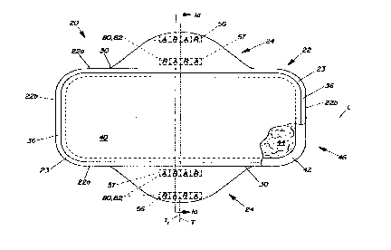
A preferred embodiment of a sanitary napkin 20 of the present
invention is shown in Figures 1-lb. As shown in Figures 1-lb, the
sanitary napkin 20 basically comprises a main body portion 22 and
two flaps 24 (shown in the extended position) joined to the main
body portion 22. Each flap 24 comprises a flap securement member
82. The main body portion 22 comprises an absorbent means
represented by an absorbent assembly 46 and a central pad
securement member (or simply pad securement member) 81. (In the
discussion that follows, unless otherwise noted, the sanitary
napkin described herein will have two flaps. While it is not
necessary that the napkin have two flaps, two flaps are preferred
over one flap. Also, while it is not necessary that the flaps be
mirror images of one another, they preferably are. Thus, the
description of one flap will be a description of the other, and,
for clarity, discussion of the second flap may be omitted.)
The sanitary napkin 20 has two centerlines, a principal
longitudinal centerline L and a principal transverse centerline T.
The term "longitudinal", as used herein, refers to a line, axis or
direction in the plane of the sanitary napkin 20 that is generally
aligned with (e. g., approximately parallel to) a vertical plane
which bisects a standing wearer into left and right body halves
when the sanitary napkin 20 is worn. The terms "transverse" or
"lateral" used herein, are interchangeable, and refer to a line,
axis or direction which lies within the plane of the sanitary
napkin 20 that is generally perpendicular to the longitudinal
direction.
The sanitary napkin 20 is comprised of a topsheet 40, a
backsheet 42, an absorbent core 44, and a pair of flaps 24. At
least a part of the topsheet 40, backsheet 42, and absorbent core
44 comprise the absorbent assembly 46 of the main body portion 22.
The flaps 24 shown in Figures 1 and la are comprised of discrete
pieces of material which are affixed to the main body portion 22.
(In alternative embodiments, such as those shown in U.S. Patent
4,917,697 issued to Osborn, the flaps 24 may be integral with the
main body portion 22. In such a case, the topsheet 40 may form
one surface of both the flaps 24 and the main body portion 22, and
the backsheet 42 may form the other surface of the same. In
SI;BSTIT~TE SHEET (R!~LE ?~)
WO 94/13236 ~ PCTlUS93/12079
8
addition, the absorbent material of the sanitary napkin 20 may
extend into the flaps 24 to form a flap absorbent core, as
described in greater detail in U.S. Patent 4,917,697.) In a
particularly preferred embodiment, the main body portion 22 will
additionally comprise recessed areas wherein the flaps can be
tucked and the flaps will comprise zones of differential
extensibility.
2. The Individual Components of the Absorbent Article
The individual components of the sanitary napkin 20 will
first be looked at in greater detail.
A. The Toosheet
The topsheet 40 is liquid permeable and when the sanitary
napkin 20 is in use, the topsheet 40 is in close proximity to the
skin of the user. The topsheet 40 is compliant, soft feeling, and
non-irritating to the user's skin. It can be made from any of the
materials conventional for this type of use. Nonlimiting examples
of suitable materials that can be used as the topsheet 40 are
woven and nonwoven polyester, polypropylene, nylon, and rayon and
formed thermoplastic films, with formed films being preferred.
Suitable formed films are described in U.S. Patent 3,929,135,
entitled "Absorptive Structure Having Tapered Capillaries", which
issued to Thompson on December 30, 1975, U.S. Patent 4,324,426,
entitled "Disposable Absorbent Article Having A Stain-Resistant
Topsheet", which issued to Mullane and Smith on April 13, 1982,
U.S. Patent 4,342,314, entitled "Resilient Plastic Web Exhibiting
Fiber-Like Properties", which issued to Radel and Thompson on
August 3, 1982, and U.S. Patent 4,463,045, entitled
"Macroscopically Expanded Three-Dimensional Plastic Web Exhibiting
Non-Glossy Visible Surface and Cloth-Like Tactile Impression",
which issued to Ahr, Louis, Mullane, and Ouellette on July 31,
1984. Formed films are preferred for the topsheet 40 because they
are pervious to liquids and yet non-absorbent. Thus, the surface
SUBSTITUTE SHEET (R! LE 26~
WO 94/13?36
21 517 21 a PCT~S93I12079
9
of the formed film which is in contact with the body remains dry
and is more comfortable to the wearer.
The sanitary napkin 20 may also be comprised of components
that are extensible (i.e., capable of stretching, particularly in
the longitudinal direction) when the sanitary napkin is worn. The
sanitary napkin ZO may capable of elongating between about 15x and
about 40X of its unstretched length. This extensibility provides
better in-use fit, comfort, and decreased staining. In other
embodiments, only limited portions of the components of the
sanitary napkin 20 are capable of stretching. Such an embodiment
(without the releasable adhesive patch of the present invention)
is described in greater detail in co-pending, commonly-assigned
Patent Application Serial No. 2,p79.537 ~ "Absorbent Article
Having Flaps and Zones of Differential Extensibility", filed
October 30, 1992,in the name of Bruce Lavash, et al.
A particularly preferred topsheet 40 for use in such an
embodiment is one which is made in accordance with U.S. Patent
4,463,045 and ring rolled to provide it with a degree of
longitudinal extensibility. Suitable processes for ring rolling
or "pre-corrugating" are described in U.S. Patent 4,107,364 issued
to Sisson on. August 15, 1978, U.S. Patent 4,834,741 issued to
Sabee on May 30, 1989 and in co-pending, commonly assigned cA
Patent Application Serial No.2,1o3.a22, entitled "Improved Method
And Apparatus For Incrementally Stretching A Zero Strain Stretch
Laminate Web To Impart Elasticity Thereto" filed by Gerald M.
Weber et al. 0n January 28, 199 2~~ cA Patent Application Serial
No. 2,1oi,2~7, entitled "Improved Method and Apparatus For
Incrementally Stretching Zero Strain Stretch Laminate Web In A
Non-Uniform Manner To Impart A Varying Degree of Elasticity
Thereto" filed by Kenneth B. Buel1 et al. On January 28, 1992,
and ca Patent Application Serial No. a,io4,236, entitled
"Improved Method And Apparatus For Sequentially Stretching Zero
Strain Stretch Laminate Web To Impart Elasticity Thereto Without
Rupturing The Web" filed by Gerald M. Weber et al. On January 28,
199 2 , The fol d 1 i nes i n the corrugat i ons of the topsheet shoul d
run in the transverse direction so the topsheet is longitudinally
extensible.
SUBSTITUTE SHEET (RL~~E 26)
WO 94/13236 21 517 G ~ ~, ~T~S93I11079
10-
Such a topsheet is described in greater detail in the
following patent applications
cA Patent Application Serial No. 2.078.815, entitled "Absorbent
Articles, Especially Catamenials, Having Improved Fluid
Directionality, Comfort and Fit" filed in the names of Thompson,
et al.; cA Patent Application Serial No. 2,073,849, entitled
"Fluid Handling Structure for Use in Absorbent Articles" filed in
the names of Thompson, et al.; and, cA Patent Application
Serial No. 2,113,416, entitled "Absorbent Gore for Use in
Catamenial oroducts' filed in the names of Buenger, et al. These
patent applications may be referred to collectively as the
"Capillary Channel Fiber" patent applications.
In addition, in preferred embodiments of the present
invention, at least a. portion of the outer surface 40a of the
topsheet 40 is treated with a surfactant. It is preferred that_
the surfactant be substantially evenly and completely distributed
across at least the portion of the outer surface 40a of topsheet
40 that overlays the main body portion 22. This can be
accomplished by any of the common techniques well known to those
skilled in the art. For example, the surfactant can be applied to
topsheet 40 by spraying, by padding, or by the use of transfer
rolls.
Treating the outer surface 40a of the topsheet 40 with a
surfactant renders the surface of the topsheet 40 more
hydrophilic. This results in liquid 'penetrating the topsheet 40
faster than it would if the surface were not treated. This
diminishes the likelihood that menstrual fluids will flow off
topsheet 40 rather than being absorbed by the absorbent core 44.
Preferably, any portions of the topsheet 40 that overlay the flaps
24 are not treated with the surfactant. This will minimize any
tendencies fluids may have to spread laterally across the flaps
and to come in contact with the wearer's thighs and other parts of
the wearer's body.
In preferred embodiments, the inner surface 40b of the
topsheet 40 is secured in contacting relation with the absorbent
core 44. This contacting relationship results in liquid
penetrating the topsheet 40 faster than if the topsheet 40 were
SU9ST~Ti~ SHEET (RULE 261
rV0 94/13236 PCT/US93/12079
X151721
not in contact with the absorbent core 44. The topsheet 40 can be
maintained in contact with the absorbent core 44 by applying
adhesive to the inner surface 40b of the topsheet 40. Suitable
adhesives useful for this purpose are described in U.S. Patent
4,917,697. The adhesives can be applied by the same methods as
the surfactant is applied to the outer surface 40a of the topsheet
40.
B. The Absorbent Core
The absorbent core 44 i s pos i ti oned between the topsheet 40
and the backsheet 42. The absorbent core 44 provides the means
for absorbing menstrual fluid. The absorbent core 44 need not
have an absorbent capacity much greater than the total amount of
menstrual fluid anticipated to be absorbed. The absorbent core 44
is generally compressible, conformable, and non-irritating to the
user's skin. It can comprise any material used in the art for
such purpose. Examples include comminuted wood pulp which is
generally referred to as airfelt, creped cellulose wadding,
absorbent roams, absorbent sponges, synthetic staple fibers,
polymeric fibers, hydrogel-forming polymer gelling agents, peat
moss, or any equivalent material or combinations of materials.
Polymeric gelling agents are those materials which, upon
contact with fluids (i.e., liquids) such as water or body fluids,
imbibe such fluids and thereby form hydrogels. In this manner,
fluids discharged into the absorbent core 44 can be acquired and
held by the polymeric gelling agent, thereby providing the
articles herein with enhanced absorbent capacity and/or improved
fluid retention performance.
The polymeric gelling agent which is employed in the
absorbent core 44 will generally comprise particles of a
substantially water-insoluble, slightly cross-linked, partially
neutralized, hydrogel-forming polymer material. The term
"parti cl es" , as used herei n, can refer to parti cl es i n any form,
such as in the form of pellets, flakes, or fibers. The
characteristics of the absorbent core 44 (including, but not
limited to the preferred types of polymer materials used therein,
SUBSTITUTE SIifET (RULE 26)
CVO 94/13236 PCTIUS93/12079
21 51721
and types of methods which can be used for preparing these polymer
particles) are described in greater detail in U.S. Patent
5,009,653 issued to Osborn and the patents incorporated by
reference in that patent,
In one preferred embodiment, the absorbent core 44 is a
laminate comprised of a layer of superabsorbent polymer material,
such as in the form of particles, disposed between two air-laid
tissues, first and second tissue layers (or "upper" and "lower"
tissue layers). The first and second tissue layers provide
containment of the superabsorbent polymer material, improve
lateral wicking of the absorbed exudates throughout the absorbent
core 44 and provide a degree of absorbency.
A suitable laminate .is the superabsorbent laminate WATER-LOCK
L-535 available from the Grain Processing Corporation of
Muscatine, Iowa (WATER-LOCK registered TM by Grain Processing
Corporation). Such superabsorbent laminates are disclosed in U.S.
Patent 4,467,012, entitled "Composition For Absorbent Film And
Method Of Preparation", which issued to Pedersen et al. on August
21, 1984, and U.S. Patent 4,260,443, entitled "Laminated Absorbent
Process", which issued to Lindsay et al. on April 7, 1981.
The absorbent core 44 may be a laminate, as described above,
which is slatted or partially slatted for longitudinal
extensibility. This slatted or partially slatted core is
described in greater detail in the Capillary Channel Fiber patent
applications.
C. The Backsheet
The backsheet 42 is impervious to liquids and, thus, prevents
menstrual fluid from soiling the clothing of the user. Any
material used in the art for such purpose can be utilized herein.
Suitable materials include embossed or nonembossed polyethylene
films and laminated tissue. A suitable polyethylene film is
manufactured by Monsanto Chemical Corporation and marketed in the
trade as Fi~m No. 8020.
In one alternative embodiment of the sanitary napkin 20
(typically in which the topsheet 40 overlays only the main body
r~~~nrTiTiITF cHEFT (RULE 261
iA
CVO 94/13236 PCT/US93I12079
a1 51721 .:. 13
portion 22 and does not extend out to form the top surface of the
flaps), the backsheet 42 may be comprised of two layers. In such
a case, the backsheet 42 may comprise a first layer of lofted
material disposed on the core-facing side 42a of the backsheet.
The purpose of the first layer is to provide a comfortable,
non-irritating surface against the body of the wearer. The lofted
layer may be comprised of any suitable material, such as a
nonwoven material. Preferably, the lofted layer comprises a
hydrophobic nonwoven material. The second layer may be disposed
on the garment side 42b of the backsheet 42, and may comprise a
fluid impervious film. A low density polyethylene material about
0.01 to about 0.05 millimeters in thickness, preferably about 0.02
millimeters in thickness, has been found to work well as this
second layer. A polyethylene film, such as is sold by the
Monsanto Chemical Corporation and marketed in the trade as Film
No. 8020 has been found particularly well suited for this second
layer. The backsheet 42 may also be made of a soft, cloth-like
material which is hydrophobic relative to the topsheet 40. A
polyester or polyolefinic fiber backsheet 42 has been found to
work well. A particularly preferred soft, cloth-like backsheet 42
material is a laminate of a polyester nonwoven material and a film
such as described in U.S. Patent 4,476,180 issued to Wnuk on
October 9,1984.
A particularly preferred extensible backsheet 42 is an
extended adhesive film Formula #198-338 manufactured by the
Findley Adhesives Company of Wauwatosa, Wisconsin which is
described in greater detail in the Capillary Channel Fiber patent
applications.
3. Assembly of Components into a Sanitary Napkin and
Formation of the Flays
A. Assembly of Components
As shown in Figures 1 and la, the topsheet 40 is secured to
backsheet 42 along a first seam, such as seam 36. The seam 36 can
be formed by any means commonly used in the art for this purpose
S'"BSTITUTE SHEET (MULE 26)
CVO 94/13236 ~ I ~ PCTIUS93112079
14
such as by gluing, crimping, or heat-sealing. The seam 36 is
illustrated in Figure 1 as extending completely around the
periphery 23 of the absorbent assembly 46 of the main body portion
22. This is a preferred embodiment for ease of construction.
(Other means of uniting the various elements can be used.)
The absorbent assembly 46 is the portion of the main body
portion 22 that contains an absorbent means, such as absorbent
core 44. The absorbent assembly 46 of the main body portion 22
has a liquid pervious body contacting surface (represented in
Figure la by topsheet 40) and an opposed liquid impervious surface
(represented in Figure la by backsheet 42). It is to be
understood that the embodiment illustrated is only one possible
embodiment, albeit a preferred one. Other possible embodiments
include one in which an absorbent core 44 is essentially
completely wrapped with topsheet before it is placed on a
backsheet. The absorbent assembly 46 of the main body portion 22
can also comprise an absorbent core which possesses sufficient
integrity to stand alone and is liquid pervious on one surface
while the other surface has been treated to render it liquid
impervious.
The absorbent assembly 46 of the main body portion 22 may be
relatively thick or relatively narrow and thin. A narrow
absorbent assembly 46 may be effective because the overall
configuration and use of sanitary napkin 20 results in absorbent
assembly 46 of the main body portion 22 being maintained in close
proximity to the body. Such proximity of the absorbent assembly
46 places it precisely where it should be: very near the body at
the vaginal opening. The absorbent assembly 46 of the main body
portion 22 can then absorb the vast majority of the menstrual
fluid (menses) before it has an opportunity to flow along the
sides of the main body portion 22. A thin absorbent assembly may
also be desired because it is typically comfortable to the user.
Figures 1 and la also show the pad securement member 81,
central pad adhesive 54, and the flap securement member 82,
releasable adhesive patch 80, which are adapted to secure the
sanitary napkin 20 to the crotch region of an undergarment.
SUBSTITUTE SHEET (RULE 26)
1VO 94/13236 2 1 5 1 7 2 1 ~ p~~gg3112079
Although the pad securement member 81 is described herein as
a central pad adhesive 54, it should be understood that fastening
means other than adhesives can be used as the pad securement
member 81. Any type of fastener or combination of fasteners used
in the art can be used for such a purpose. For example, the
sanitary napkin 20 could be secured to the wearer's undergarment
by the fastener described in U.S. Patent 4,946,527 entitled
°Pressure-Sensitive Adhesive Fastener and Method of Making the
Same" issued to Battrell on August 7, 1990. Other examples of
fastening means would include mechanical fasteners such as those
which are well known in the art. Particularly preferred
mechanical fasteners are disclosed in conmonly-assigned,
co-pending, ca Patent Application Serial No. 2,109,621 , "Screen
Printing Method for Manufacturing a Refastenable Mechanical
Fastening System and Fastening System Produced Therefrom", filed
June s, 1992, in the name of Dennis A. Thomas and David J. K.
Goulait, and commonly-assigned, co-pending, ca Patent
Application Serial No. 2,109,620, "Method for Manufacturing a
Refastenable Mechanical Fastening System having azimuthally angled
Prongs and Fastening System Produced Therefrom", filed June s ,
199 2, in the name of Dennis A. Thomas and David J. K. Goulait.
Particularly preferred mechanical fasteners for use with absorbent
articles such as sanitary napkins are disclosed in ca Patent
Application Serial No. 2,151,4x5 , P6G Case No. 4786, entitled
'Disposable Absorbent Article Having An Improved Mechanical
Fastening System", filed December s, 1993, in the names of David
J. K. Goulait, Dennis A. Thomas, and Maureen E. Stanley, and ca
Patent Application Serial No. 2,14s,946, P8G Case 4785,
entitled "Non-Abrasive Mechanical Fastening System and Process of
Manufacture Therefor', filed December s, 1993, in the names of
David J. K. Goulait and Dennis A. Thomas ,
Additionally,
the releasable adhesive patch 80 described herein may also be used
as the pad securement member 81. For simplicity, however, the pad
securement member 81 will be described in terms of a conventional
adhesive attachment means, i.e., central pad adhesive 54.
Sl,~3STITUTE SHEET rat n_F 2g~
A
WO 94/13236 21 517 21 ~ . p~/Ug93112079
16
The central pad adhesive 54 provides an adhesive attachment
means for securing main body portion 22 in the crotch portion of a
panty. Suitable adhesive fasteners are described in greater
detail in U.S. Patent 4,917,697. The adhesive attachment means
are respectively covered by removable release liners, central pad
release liner 58a and flap release liner 58b. The
pressure-sensitive adhesives should be covered with release liners
to protect the adhesives from dirt, to keep the adhesives from
drying out, and to keep the adhesives from sticking to extraneous
surfaces prior to use. Suitable release liners are described in
U.S. Patent 4,917,697.
The flap securement member 82 is used to assist in
maintaining the flap 24 in position after it is wrapped around the
edge of the crotch portion of the panty as described below. The
flaps 24 can be maintained in position by attaching the flaps 24_
to the undergarment, or to the opposing flap.
While a preferred sanitary napkin embodiment of the present
invention has been described, numerous other sanitary napkin
embodiments having flaps are available and are disclosed in the
literature. These could be provided with the releasable adhesive
patch 80 of the present invention. In particular, sanitary
napkins having flaps are disclosed in ~A Patent Application
Serial No. 2,028,288, entitled "Sanitary Napkin Having Laterally
Extensible Means for Attachment to the Undergarment of the
Wearer", filed opt. 23/90; in the name of Osborn, et al.; U.S.
Patents 5,009,653 and 4,950,264, both entitled "Thin, Flexible
Sanitary Napkin" which issued to Osborn on April 23, 1991 and
August 21, 1990, respectively,
U.S. Patent 4,917,697 entitled "Sanitary Napkin
Having Flaps and Stress Relief Means" which issued to Osborn, III,
et al. on April 17, 1990,
U.S. Patent 4,900,320, entitled
"Sanitary Napkin With Panty Gathering Flaps" which issued to McCoy
on February 13, 1990, U.S. Patent 4,687,478, entitled "Shaped
Sanitary Napkin With Flaps", which issued to Van Tilburg on August
SUBSTITUTE SHEET (RULE 26)
CVO 94/13236 ~ 1 517. 21 ,.~i PCT/US93/12079
17
18, 1987, U.S. Patent 4,608,047, entitled "Sanitary Napkin
Attachment Means", which issued to Mattingly on August 26, 1986,
U.S. Patent 4,589,876, entitled "Sanitary Napkin", which issued to
Van Tilburg on May 20, 1986, U.S. Patent 4,285,343, entitled
"Sanitary Napkin", which issued to McNair on August 25, 1981, U.S.
Patent 3,397,697, entitled "Disposable Sanitary Shield For
Undergarments", which issued to Rickard on August 20, 1968, and
U.S. Patent 2,787,241, entitled "Sanitary Napkin", which issued to
Clark on April 2, 1957.
Suitable absorbent articles in the form of pantiliners are
disclosed in U.S. Patent 4,738,676 entitled "Pantiliner" issued to
Osborn on April 19, 1988. Suitable absorbent articles, at least
some of which are in the form of adult incontinence products, ai-e
described in cA Patent Application Serial Number 2,o9s,5o2,
entitled "Absorbent Article Having Rapid Acquiring Wrapped
Multiple Layer Absorbent Body" filed by Barry R. Feist, et al. on
l5ec. 20, 1991.
B. Construction of the Flacs
The characteristics of the flaps 24 will now be looked at in
greater detail. The general con3truction of flaps 24 suitable for
use in the present invention (without the releasable adhesive
patch 80 of the present invention) is described in greater detail
in the patents incorporated by reference herein, such as U.S.
Patent 4,917,697 issued to Osborn; cA Patent Application Serial
No. 2,079,537, "Absorbent Article Having Flaps and Tones of
Differential Extensibility", filed October 3~,1992,in the name of
Bruce Lavash, et al.; and cA Patent Application Serial No.
Sl;BSTITUTE SHEET (RUSE 26)
~A
«
'O 94/13:36 Z 1 517 21 - PCTlUS93/12079
18
2,0~9,55~, "Absorbent Article Having Inwardly-Folded Pleated
Flaps", filed sept. 30, 1992 in the name of Kaoru Niihara and
Thomas W. Osborn, III.
The overall size of the flaps 24 can be readily selected by
those skilled in the art. Preferably, the flaps 24 are sized so
that the sanitary napkin 20 is from about 10 to about 23
centimeters wide between the distal edges 34 of the flaps at their
greatest separation. Preferably each flap 24 is from about 5 to
at least about 19 centimeters long in the direction parallel to
the principal longitudinal centerline L of the sanitary napkin.
However, the flaps 24 may be as small as 0.5 centimeters long in
the direction parallel to the principle longitudinal centerline L.
The shape of the flaps 24 can be selected by those skilled in
the art. Preferably, not only are the flaps 24 mirror images of
each other, the two halves of each flap 26 and 28 are also-
symmetrical about the flap transverse centerline T1. (It should
be understood that the shape and orientation of the flaps
described herein are those of a preferred embodiment. They are
not mandatory design features.)
Preferably, as in the sanitary napkin 20 illustrated in
Figure 3, the flaps 24 are positioned slightly forward of the
principal transverse centerline T of the sanitary napkin. (In
such a case, the flap transverse centerl ine T1 does not coincide
with the principal transverse centerline T of the sanitary napkin
20.) The flaps 24, however, are preferably evenly spaced from the
principal longitudinal centerline L of the sanitary napkin.
In a preferred embodiment, the flaps 24 are joined with the
main body portion 22 along lines of juncture 30. The lines of
juncture can be concave, straight, or convex relative to the
principal longitudinal centerline L. The lines of juncture 30 may
comprise those lines or areas where separate flap eieaients are
joined to the main body portion 24. Alternatively, when the flaps
24 are integral with the main body portion 22, the lines of
juncture 30 may represent lines of demarcation between the main
body portion 22 and the flaps 24 (although it is not necessary
that there be a precise line of demarcation).
SUBSTITUTE SHEET (RUSE 26)
~A
WO 9~/I3236 2 1 5 1 7 2 1 WT~S93I12079
19
The flaps 24 can be joined with the main body portion 22 in a
number of different manners. Many of the different ways a
component (such as the flaps 24) can be "joined to" or "associated
with", etc. another component, are set forth in the definitions of
these terms contained in U.S. Patent 5,007,906 entitled "Decoupled
Sanitary Napkin" which issued to Osborn, et al. on April 16, 1991.
When the flaps comprise separate elements, they can be joined to
the main body portion 22 by any techniques known to those skilled
in the art. Such techniques include, but are not limited to
adhesives, heat and/or pressure, ultrasonics, etc.
It is not necessary that the flaps 24 extend from (or be
joined along) the longitudinal edges 22a of the main body portion
22. The flaps 24 can joined inward (or "inboard") from the
longitudinal edges 22a toward the longitudinal centerline.
The flaps 24 can, thus, each be joined to the main body
portion 22 along the principal longitudinal centerline L, or along
the longitudinal edges 22a of the main body portion 22, or at any
place between the principal longitudinal centerline L and the
longitudinal edges 22a of the main body portion 22. The flaps 24
- will, of course, generally be on opposite sides of the principal
longitudinal centerline L.
C. Releasable Adhesive Patch
1. Releasable Adhesive Patch in General
Figures 1, la and lb show a preferred embodiment of a
sanitary napkin of the present invention. The sanitary napkin 20
of the present invention comprises at least one releasable
. adhesive patch 80. Preferably, as shown in Figure 1, the sanitary
napkin 20 has two releasable adhesive patches 80, one for the flap
securement member 82 of each flap 24.
The overall size and shape of the releasable adhesive patch
80 can be readily selected by those skilled in the art.
Preferably, the releasable adhesive patch 80 is sized and shaped
so that it will provide a secure attachment of the flap 24 to the
SUBSTITUTE SH~~T (RULE 26)
1V0 94/13236 PCT/US93/12079
undergarment. However, it should be understood that the size,
shape, and orientation of the releasable adhesive patch 80
described herein are those of a preferred embodiment. They are
not mandatory design features. For example, each flap 24 could
comprise a releasable adhesive patch 80 which is positioned closer
to the distal edge 34 of the flap 24 or which is positioned closer
to the proximal edge 32 of the flaps.
The releasable adhesive patch 80 will be any patch of
material that will adhere to itself with sufficient tenacity to
remain in place prior to use, but should be readily removable when
the flap 24 is ready to be used. The releasable adhesive patch 80
should also protect itself from contaminants, from drying out, and
from sticking to the skin of the wearer and/or extraneous surfaces
prior to use. Additionally, the releasable adhesive patch 80 is
preferably flexible so as not to inhibit the flexibility of the
flap 24.
Referring to Figures 1 and la, each of the flaps 24 comprises
a releasable adhesive patch comprising a first half 56 and a
second half 57. The first half 56 is positioned adjacent to the
distal edge 34 of the flap 24 and the second half 57 is positioned
adjacent the proximal edge 32 of the flap 24. The second half 57
is positioned such that it superposes the first half 56 when the
flap 24 is folded along a longitudinally extending fold line 62 as
shown in Figure lb.
The releasable adhesive patch 80 is shown in Figures 1 and la
as comprising a first half 56 which is discrete from the second
half 57. It should be understood that the first half 56 and
second half 57 of the releasable adhesive patch 80 may be integral
with each other. Additionally, although the first half 56 and the
second half 57 are shown in Figure 1 as having a fold line 62
oriented parallel to the longitudinal centerline L, the first half
56 and the second hal f 57 may have a fol d 1 i ne on ented paral 1 el
to the transverse centerline T or oriented in any other desired
direction.
Although the first half 56 is shown positioned substantially
adjacent to the distal edge 34 of the flap 24 in Figure 1, the
first half 56 may be positioned closer to the proximal edge 32 of
ci mcT~TUTE SHEET (RULE 26)
..O 94/13236 PCT/US93/12079
~1 51721 -f
the flap 24, or anywhere between the distal edge 34 and the
proximal edge 32. Preferably, the first half 56 will be
positioned about 2 mm to about 10 mm from the distal edge 34 of
the flap 24 to provide the user with a graspable tab.
Additionally, although the second half 57 is positioned on
the flap 24 adjacent the proximal edge 32, the second half 57 may
be positioned on a portion of the main body portion 22. However,
it is preferred that the first half 56 and second half 57 be
positioned on the flap 24. It is also possible for each flap 24
to have more than one releasable adhesive patch 80. However, a
single adhesive patch 80 for each flap 24 is preferred.
When the user of the sanitary napkin 20 wishes to expose the
adhesive patch 80 and secure the flap 24 to the underside of the
user's undergarment, the user simply pulls the distal edge 34 of
the flap 24 thereby unfolding the flap 24 from its folded
configuration and simultaneously peeling the first half 56 from
the second half 57. Preferably, the act of unfolding the flap 24
from its folded configuration and simultaneously peeling the first
half 56 frcm the second half 57, can be accomplished using one
hand.
2. Adhesive Patch Comprising Alternatin4 Zones of
Adhesive and Release Material
The releasable adhesive patch 80 may also comprise
alternating zones of adhesive and release material. Referring to
Figure 8, there is shown a portion of a sanitary napkin similar to
the sanitary napkin of Figure 1. The flap 24 of the sanitary
napkin 20 of Figure 8, comprises a releasable adhesive patch 80
havi ng a fi rst hal f 56 and a second hal f 57. The fi rst hal f 56
comprises alternating adhesive zones A and release zones R. The
second half 57 also comprises alternating adhesive zones A and
release zones R. The alternating adhesive zones A and release
zones R of the second half 57 are complimentary with the adhesives
zones A and release zones R for the first half 56, i.e., the
second half 57 has a release zone for each adhesive zone of the
SUBSTITUTE SHEET (RULE 26)
WO 94/13236 PCT/US93/12079
22
first half 56, and the second half 57 has an adhesive zone A for
each release zone R of the first half 56.
The adhesive zones A provide an adhesive attachment means for
securing the flap 24 in position after it is wrapped around the
edge of the crotch portion of the panty as described below.
Suitable adhesives for forming the adhesive zones A are described
in greater detail in U.S. Patent 4,917,697.
The release zones R provide a release means for the adhesive
zones A. The release zones R preferably comprise a release
materi al that i s joi ned to a porti on of the wi ng 24, and may be
formed in several different ways. For example, the release zones
R may be formed by securing any commercially available release
liner to a portion of the flap 24. An example of a suitable
release liner is a polyethylene film, the adhesive contacting side
of which has been silicone treated to provide easy release from
the adhesive zone A. Other examples of suitable release liners
are BL 30 MG-A SILOX E1/0 and BL 30 MG-A SILOX 4 P/0 both of which
are manufactured by the Akrosil Corporation. The release zone can
be joined to the flap 24 by any of the techniques known to those
s ki 11 ed i n the art . Such techni ques i ncl ude but are not 1 i mi ted
to adhesives, heat and/or pressure, ultrasonics, etc.
The release zone R may also comprise a portion of the flap 24
which consists entirely or partially of a material which can act
as a suitable release member. Examples of materials which can act
as suitable release members and which can be used to form the
release zones R, ~ould include woven and nonwoven polyester,
polypropylene, nylon, polyethylene, and plastic films, which have
been treated with a silicone such as SILOX E1/0, SILOX 4 P/0,
SILOX H1A/0, and SILOX H2A/0, all of which are manufactured by the
Akrosil Corporation of Menasha, Wisconsin.
Preferably, the release zone R is formed by treating (e. g.,
coating, painting, spraying, impregnating, etc.) portions of the
flap 24 with a substance, such as silicone, so that the treated
portion of the flap 24 will function as suitable release zones R.
Suitable substan es for treating portions of the flap 24 woul.dr..>
include a silicone such as SILOX El/0, SILOX-.4.P~O, SILOX H1A/0, .
and SILOX H2A/0; 11 of which are manufactured by the Akrosil
SUBSTITUTE SHEET (RULE 26)
.~O 94/13236 21 5 '~ 7 21 ~.r PCT/US93/12079
23
Corporation. More preferably, the release zones R are formed by
spray coating portions of the flap 24 with SILOX H2A/0.
Additionally, a silicone compound may be cross-linked or reacted
to the surface to imbolize the release material.
Referri ng to the rel easabl a adhes i ve patch 80 of one of the
flaps 24, the release zones R of the second half 57 are positioned
on the flap 24 such that the adhesive zones A of the first half 56
will overlie the release zones R of the second half 57 when the
flap 24 is in a folded configuration. likewise, the release zones
R of the first half 56 are positioned on the flap 24 such that the
adhesive zones A of the second half 57 will overlie the release
zones R of the first half 56 when the flap 24 is in a folded
config~ation. The release zones R will protect the adhesive
zones A from dirt, from drying out, and from sticking ~o
extraneous surfaces. The contact between the release zones R and
the adhesive zones A of the releasable adhesive patch 80, also
maintains the flap 24 in a folded configuration until the flap is
ready to be'used.
Although the first half 56 is shown in Figure 8 as being
substantially adjacent to the second half 57, the first half 56
and the second half 57 may be positioned further away from each
other. Additionally, although the first half 56 is positioned on
the flap 24 adjacent the distal edge 34, the first half 56 may be
positioned closer to the proximal edge 32 of the flap 24 or
anywhere betw~n the distal edge 34 and the proximal edge 32.
However, it is preferred that the first half 56 be positioned 2
mm-10 pan from the distal edge 34 to provide a graspable portion
for the user.
It shoul d al so be understood that . al though the fol d 1 i ne 62
between the first half 56 and the, second half 57 is oriented
paralle l to the longitudinal centerline L, the fold line 62 may be
oriented paral lel to the transverse- centerl ine T or at any other
angle relative to the sanitary napkin 20.
Referring to Figure 9, there is shown a portion of a sanitary
napkin substantially the same as the sanitary napkin shown in
Fi gure 8. However, the f i rst hal f 56 and the second hal f 57 of
the releasable adhesive patch 30, each comprise two rows of
~~~~°~-6T~'~-E Si~EET (RULc 2~~
WO 94/13236 ~ PCTIL1S93/12079
.1517 ~ ~ v~ 24
2, -alternating adhesive zones A and release zones R. The adhesive
zones A and release zones R of the second half 57 are oriented and
arranged such that they will overlay the release zones R and
adhesive zones A, respectively, of the first half 56 when the flap
24 is folded along fold line 62.
Although the flap 24 of Figure 9 is shown as comprising only
one fold line 62, it is contemplated that a flap 24 may be
provided with two or more fold lines. Referring to Figure 9a
there is shown a transverse cross sectional view of the flap 24 of
Figure 9. Figure 9b is the same transverse cross sectional view
shown in Figure 9a with the exception that the flap 24 is folded
along fold line 62. (Figure 9a additionally shows alternate fold
lines 62' and 62 " .) Figure 9c shows a transverse cross sectional
view of the sanitary napkin 20 of Figure 3a with the exception
that the flap is folded along two fold lines, alternate fold lines
62' and 62" . Figure 9d shows the sanitary napkin of Figure 9c
with the flap additionally folded along fold line 62 to form three
separate folds.
Alternate Embodiments
Although both halves of the releasable adhesive patch 80 are
shown in Figures 1-lb as being joined to a portion of the flap 24,
i t i s not necessary that both hal ves, 56 and 57, be secured to a
portion of the flap 24. The second half 57 may be joined to the
flap 24, main body portion 22, or any other portion of the
sanitary napkin 20. It is also possible for the central pad
adhesive 54 to comprise a releasable adhesive patch 80 such as
that described above with respect to the flaps 24.
In an alternate embodiment, the second half 57 of the
releasable adhesive patch 80 may be removably secure to the first
half 56 without the flap 24 being folded onto itself or the main
body portion 22. Figure 7 is a transverse cross-sectional view of
a portion of a sanitary napkin 20 showing one of the flaps 24 and
a portion of the main body portion 22. In this embodiment, the
second half 57 of the releasable adhesive patch 80 is hingedly
joined to the flap 24. Second half 57 is secured to hinge member
~~ ~~~~ E~s~~ ~ I c ~~Et i ~~t~~.~ ~~f
. O 94113236 , PCTIUS93/12079
2151721.:
99 which is secured to the flap 24 at bond area'97. When the
second half 57 is peeled from the first half 56, it remains joined
to the fl ap 24 at the bond area 97. The bond area 97 may be a
single discrete spot bond, group of spot bonds, a solid line of
bond i ng or a segmented 1 i ne of bond i ng . The bond area 97 may be
located laterally inboard or outboard, or longitudinally forward
or behind the flap adhesive 56. The hinge member 99 may be any
flexible material. Preferably, the hinge member 99 is made of
materials commonly used in the manufacture of disposable absorbent
articles such as polymeric nonwovens or films.
A further alternate embodiment is shown in Figure 7a. After
peeling the second half 57 from the first half 56, the user would
reattach the loose end of the hinge member 99 to the flap 24 with
a bonding material 98. This prevents the loose end of the hinge
member 99 from moving freely and potentially interfering with the
application of the flap 24. The bonding material 98 could be
originally located on either the back of the hinge member 99, on
the flap 24 or the main body portion 22. The bonding material 98
could also be a cohesive material, such as a complementary
cohesive adhesive, originally located on both the hinge member 99
and the flap 24 or the hinge member 99 and the main body portion
22. As used herein, the term "complementary cohesive adhesive"
will refer to an adhesive which will adhere to the same or similar
adhesive but not to other surfaces.
Figures 5-5b show examples of suitable arrangements for the
adhesive zones A and release zones R of the releasable adhesive
patch 80. However, it should be understood that these are just
examples, and there are many other suitable arrangements which may
be used.
D. Function Of The Sanitary Napkin With Relation To
The Wearer's Under4arment
The function of the sanitary napkin of the present invention
will now be described in greater detail with relation to the
wearer's undergarments.
~~~~~;~~~~ sHE~~ ~RU~ ~ ~~
a
CVO 94/13236 a PCT/US93/12079
26
Figure 6 is a depiction of the crotch portion 14 of an
undergarment 11 of the type commonly worn by many women and well
known as a panty. A panty 11 comprises a front section 10, a back
section 12, and a crotch portion 14 which joins the front and back
sections. The crotch portion 14 comprises two side edges 16 and
center crotch portion 18.
The sanitary napkin 20 of the present invention may be
utilized by removing the release liner 58 of the central pad
adhesive 54 and placing the sanitary napkin 20 in a panty 11 as
shown in Figure 6b. The center of main body portion 22 is placed
in crotch portion 14 of the panty with one end of main body
portion 22 extending towards the front section 10 of the panty and
the other end towards the back section 12. The backsheet 42 is
placed in contact with the inner surface of center crotch portion
18 of the panty. Central pad adhesive 54 maintains main body
portion 22 in position. The user grasps and pulls the distal edge
34 of the flap 24, thereby peeling the first half 56 from the
second half 57 of the releasable adhesive patch 80. The distal
portions of flaps 24 are then folded around the side edges 16 of
the panty. The adhesive patches 80 secure the flaps 24 to the
underside of the panty as shown in Figure 6a.
E. Sanitary Napkins Havin4 Tucked FlaQS and a
Releasable Adhesive Patch
Preferably, the sanitary napkin will have the flaps tucked
into a recessed area and will have at least one zone of
differential extensibility. However, it is also possible to have
a san i tary napki n of the present i nventi on wi th the fl aps tucked
into a recessed area without having zones of differential
extensibility. It is also possible to have zones of differential
extensibility without having the flaps tucked into a recessed
area. Figures 2, 2a, and 2b show a sanitary napkin 20 embodiment
of the present invention having a releasable adhesive patch 80 and
a recessed area 68 for receiving the flaps 24.
As used herein the terms "optional flaps" or "tucked flaps"
shall refer to the flaps of an absorbent article, which are tucked
~~~'~~'~ ~ ~~~ SHE~~ ~Pu~~ ~~
.:O 94/13236 PCT/US93/12079
21 5172 ~, 2
or are capable of being tucked into a recessed area 68. A flap is
capable of being tucked into a recessed area if it is joined to
the sanitary napkin such that at least a portion of the flap may
be positioned between the decoupled portion of a retaining member
and the absorbent assembly of the main body portion. Referring to
Figure 2, the sanitary napkin 20 basically comprises a main body
portion 22 and two flaps 24 (shown in the extended position)
joined to the main body portion 22. The main body portion 22
comprises an absorbent means represented by an absorbent assembly
46 and two retaining members 78 joined to the absorbent assembly
46.
The retaining member 78 comprises a pair of end regions 93
and a center region 94 positioned between and joined to the end
regions 93. At least a portion of the end regions 93 are joined
to the absorbent assembly 46. At least a portion of the center
region 94 is detached or decoupled from the absorbent assembly 46.
The area between the decoupled center region 94 and the absorbent
assembly 46, forms a recessed area 68 wherein a portion of at
least one of the flaps 24 may be tucked. The end regions 93 are
each joined to the absorbent assembly 46 at a point of connection
72. As used herein, the term "point of connection" refers to
regions where the retaining member 78 is joined to the absorbent
assembly 46 of the main body portion 22. These regions can be of
any shape or configuration, but they are not limited to spots or
points. Thus, these regions can comprise flanges, strips,
intermittent lines, spots, and the like.
The retaining member 78 can be joined to the absorbent
assembly 46 of the main body portion 22 in a number of different
manners. Many of the different ways a component (such as the
retaining member 78) can be "joined to" or "associated with", etc.
another component are set forth in the definitions of these terms
contained in U.S. Patent 5,007,906 entitled "Decoupled Sanitary
Napkin" which issued to Osborn, et al. on April 16, 1991. When
the retaining member is comprised of an element discrete from the
absorbent assembly 46, i.e. is not integral with the topsheet,
backsheet, etc, it can be joined to the absorbent assembly 46 by
any techniques known to those skilled in the art. Such techniques
a y
CVO 94!13236 PCTIUS93/12079
2151721 28
include, but are not limited to adhesives, heat and/or pressure,
ultrasonics, etc. The point of connection 72 may comprise
flanges, strips, intermittent lines, spots, and the like, or may
comprise combinations of flanges, strips, intermittent lines,
spots, and the like. Therefore, the point of connection 72 may be
a line which is concave, straight, or convex and may form any
angle relative to the principal longitudinal centerline L.
The retaining member 78 is generally compliant soft feeling
and non-irritating to the users skin. The retaining member 78 is
preferably made from any of the materials conventionally used for
sanitary napkins 20. Examples of suitable materials that can be
used for the retaining member 78 are woven and nonwoven polyester,
polypropylene, nylon, and polyethylene, as well as plastic films.
The retaining member 78 may be comprised of one or more of tfi a
elements of the absorbent assembly 46, e.g., topsheet 40,
backsheet 42, etc. Preferably, the retaining member 78 will
comprise a piece of material discrete from the topsheet,
backsheet, etc.
Referring to Figures 2 - 2b, the sanitary napkin 20 has two
recessed areas 68, one on each side of the longitudinal centerline
L. It can be seen from Figures 2a and 2b that the flaps 24 are
integral with the retaining members 78. The point of connection
72 of each retaining member 78 comprises a combination of a
straight line bond 92 and two spot bonds 91. The line bond 92
joins a portion of the center region 94 of the retaining member 78
to the absorbent assembly 46. The two spot bonds 91 join a
portion of the end regions to the absorbent assembly 46. The
portion of the center region 94 which is decoupled from the
absorbent assembly 46 of the main body portion 22 forms the
recessed area 68. Although the spot bonds 91 are shown in Figure
2 as being positioned adjacent to the longitudinal edge 22a of the
main body portion 22, the spot bonds 91 may be positioned anywhere
between the longitudinal edge 22a of the main body portion 22 and
the longitudinal centerline L.
Figure 2b is a lateral cross-sectional view of the sanitary
napkin 20 of Figure 2a showing the flaps 24 tucked into the
recessed areas 68 in a folded configuration. Each flap 24 of the
~~~~T~T~ i ~ S~lt~ E ~ ~~~~ ~c~
WO 94/13236 21 517 2 ~ PCTlUS93/12079
29
sanitary napkin 20 has a first longitudinal fold 62' which is made
upward toward the absorbent assembly 46 and a second fold 62 "
which is again made upward toward the absorbent assembly 46. This
forms a tucked flap 24 which is configured in an S-fold. This
configuration allows the distal edge 34 of the flap 24 to form a
graspable tab member 90.
Each of the folded flaps 24 may be provided with one or more
breakable bonds 86 which hold the flaps 24 in a folded
configuration. Examples of suitable breakable bonds 86 would
include adhesive spot beads, spot welds/heat seals, and cohesive
materials such as a complementary cohesive adhesive. The
breakable bond 86 may secure a portion of the flap 24 to a portion
of the main body portion 22 as shown in Figure 2b. Alternatively,
the breakable bond 86 may secure a portion of the flap 24 'to
another portion of the same flap 24, or to a portion of the
retaining member 78.
Preferably each tucked flap 24 will be provided with a
graspable tab member 90. As used herein, the term "tab member"
will refer to an element or component of the sanitary napkin 20
which protrudes form the recessed area 68 and may be used to
remove the flap 24 from the recessed area 68. A preferred tab
member 90 is formed by folding, pleating, or corrugating the flap
24~such that the distal edge 34 of the flap 24 protrudes from the
mouth 76 of the recessed area 68. There are many different fold
configurations which will result in the distal edge 34 of the flap
24 protruding from the mouth 76 of the recessed area 68. An
example of particularly preferred fold configurations which
results in the distal edge of the flap 24 forming a tab member 90,
are shown in Figure 2b, 3b, and 7a. Other suitable fold
configurations will be readily apparent to those skilled in the
art.
Sanitary napkins having tucked flaps 24 and various methods
for forming the recessed areas 68, are discussed in greater detail
in the coamonly-assigned, co-pending, ca Patent Application
Serial No. 2,13~,6s2, "Absorbent Article Having Tucked Flaps",
filed June 23, 1993, in the name of Thomas W. Osborn, III and
v' ~~~ j ~~ ~r~.r~r I~~ '1 t_'
t ~ 1 v i. v.. ~. ~
WO 94/13236 2 1 5 1 7 2 1 ~T~S93/12079
Bruce W. Lavash
F. Sanitary Napkin Having Flaos With Zones of
Differential Extensibility and a Releasable
Adhesive Patch
Preferably, the sanitary napkin will have at least one zone
of differential extensibility (or "zone of extensibility", or
simply "zone") 50. Preferably, as shown in Figure 3, the sanitary
napkin 20 has four zones of differential extensibility 50, one in
each quarter of the sanitary napkin 20. The zones of differential
extensibili~y 50 are preferably located along a portion of the
fold line where the flaps 24 are folded around the wearer's panty
crotch. The fold line will typically be located along or adjacent
the longitudinal juncture 30 of each flap 24. Since the -terms
"portions', 'zones', and "regions', as used herein, refer to
general areas, the zones of differential extensibility 50 and the
corner regions 52 are,. thus, not limited to points which lie
precisely on the lines of juncture 30. Typically, they will
include both those points which lie on the lines of juncture 30 as
well as the surrounding areas of the sanitary napkin 20 (which
include the aforementioned fold lines). The longitudinal
junctures, thus, typically serve as good approximations for the
location of the zones of differential extensibility 50.
Figures 3, 3a, and 3b show an embodiment of the present
invention which has one preferred type of zones of differential
extensibility 50. In the embodiment shown in Figures 3, 3a, and
3b the zones of differential extensibility 50 comprise portions of
the sanitary napkin 20 that have slack provided therein. These
portions of the sanitary napkin 20 comprise at least the flap
corner regions 52'.
The slack is provided to the sanitary napkin 20 in the
embodiment shown in Figures 3, 3a, and 3b by pleating and then
gathering in portions of the flaps. The flaps 24 are pleated or
folded with generally longitudinally-oriented fold lines 62. The
fold lines 62 can run along and/or outboard (or even inboard) of
SUB~~';~'~T~ S~!~=T ~ r'~.J'~ 20"
O 94/13236 21 517 21 ~ PCT/US93/12079
31
the juncture 30 of the flaps and the main body portion 22. The
pleated sections of the flaps (the "pleats") 64 are preferably
folded on top of each other (that is, stacked perpendicular to the
plane of the sanitary napkin). In alternative embodiments, they
may be folded and arranged side-by-side. The pleated sections are
gathered in or restrained from opening by a flap pleat restraint
66 located along the flap transverse centerline T1. This provides
the sanitary napkin, and particularly the flaps 24, with corner
regions which are extensible in the transverse direction and with
center portions 27 (along the flap transverse centerline T1) which
are not.
The zones of differential extensibility 50 are most
preferably located at those points where the edges 35 of the flaps
24 intersect the edges 16 of the panty when the sanitary napkin 20
is worn.
The total area covered by the zones of differential
extensibility 50 can vary widely. The area can cover a relatively
large portion of the sanitary napkin, provided there remain some
portions of the sanitary napkin adjacent at least portions of the
principal longitudinal centerline and the flap transverse
centerline that are less extensible. The zones of differential
extensibility 50 can be provided along the entire juncture 30 of
the flaps 24 with the main body portion 22. In alternative
embodiments, the zones of differential extensibility 50 can be
provided throughout the entire flap (for instance, if the entire
flap is pleated with longitudinally-oriented pleats).
The flap pleat restraint 66 can be any suitable type of
element capable of keeping a portion of the pleated material from
unfol di ng . The fl ap pl eat restrai nt 66 can be 1 ocated al ong the
flap transverse centerline T1, or it can be spaced some distance
away from the flap transverse centerline T1. The flap pleat
restraint 66 is, however, preferably located at some place along
the flap transverse centerline T1. This creates flaps with pleats
whi ch are abl a to open up an equal amount i n both the front and
back halves 26 and 28 for a preferred fit around the panty crotch.
The flap pleat restraint 66 is also preferably located more toward
the mouth 65 of the fold as opposed to the crease 67 of the fold
E I r,-s' ~ p.~.. "~ ~ ( '~ f ~ ; ~
t~y ~~C ~< < s_ ~ ~m.:L.:.
S~~~S
WO 94113236 PCT/US93112079
21 51'21
as shown in Figure 3. The amount of differential extensibility of
the flap will increase as the flap pleat restraint 66 is
positioned close to the mouth 65 of the fold. The flaps 24 can
have two flap pleat restraints 66, one located along (or spaced
some distance away from) the flap transverse centerline TI for
each flap, or they can have a single flap pleat restraint that
spans from one flap to the other.
The flap pleat restraints 66 shown in Figure 3a are
"interior" restraints, i.e., they are located in between two
pleated or folded sections 64 of the flaps 24. In alternative
embodiments, the flap pleat restraint 66 can be of a type which
secures the pleated sections 64 of the flaps 24 from outside (or
exterior) of the pleated sections.
Referring to Figure 3a and 3b, each flap 24 of this
embodiment has a first portion 95 and a second portion 96. The
first portion 95 comprises a pleat 64 which is secured by flap
pleat restraints 66. The second portion 96 comprises the first
half 56 and the second half 57 of the releasable adhesive patch
80.
The first portion 95 of each flap 24 has two fold lines 62
that form the pleat 64. The first fold that forms the pleat 64 is
made inward toward the garment side 20b of the sanitary napkin 20.
The second fold that forms the pleat 64 is also made inward
towards the garment side 20b of the sanitary napkin 20. The fold
line 62 that is closest to the proximal edge 32 of the flap 24
when the first portion 95 is unfolded, comprises a first
pleat-forming fold line 62'. The fold line 62 that is located
farther away from the proximal edge 32 of the flap 24 when the
first portion 95 is unfolded, comprises a second pleat-forming
fol d l i ne 62" .
The pleat 64 of the first portion 95 of the flap 24, is
positioned inboard of the longitudinal edge 22a of the main body
portion 22 when the sanitary napkin 20 is looked at from a top
plan view such as in Figure 3. This results in the pleat 64 of
the first portion 95 being positioned in the recessed area 68
between the retaining member 78 and the backsheet 42 of the main
_ ,....,..~~ Tt: . ~~;~ .
.~O 94/13236 PCT/US93/12079
X151721 ~ 33
body portion 22 when the flap 24 is extended as shown in Figure 3a
or when the flap is tucked as shown in Figure 3b.
Again referring to Figures 3, 3a, and 3b, the second portion
96 of each flap 24 comprises the first half 56 and the second half
57 of the releasable adhesive patch 80. The first half 56 is
positioned adjacent to the distal edge 34 of the flap 24 and the
second half 57 is positioned adjacent to the first portion 95 of
the flap 24, such that when the second portion 96 is folded along
a longitudinally extending fold line 62, the first half 56 will
superpose the second half 57 and be removably secured thereto.
A transverse, cross-sectional view of a particularly
preferred sanitary napkin embodiment of the present invention, is
shown in Figure 4 and 4a. The embodiment shown in Figures 4 and
4a is similar to the embodiment shown in Figures 3-3b, i.e., t'he
flaps 24 are extensions of the retaining member 78 which is joined
to the backsheet 42 of the main body portion 22 along the lines of
connection 72. However, the flaps 24 are arranged in a different
configuration when they are tucked, as shown in Figure 4a, and
when they are extended, as shown in Figure 4.
Referring to Figure 4, each flap 24 may again be thought of
as having a first portion 95 and a second portion 96. The first
portion 95 of the flap 24 comprises a pleat 64 which is secured by
the flap pleat restraints 66, and comprises the second half of the
releasable adhesive patch 80 joined to the body-facing side 95b of
the first portion 95. The second portion 96 comprises the first
half 56 joined to the garment-facing side 96b of the second
portion 96.
The pleat 64 of the first portion 95 of the flap 24, has two
longitudinally extending fold lines 62. The fold line that is
closest to the proximal edge 32 of the flap 24 when the first
portion 95 is unfolded, comprises a first pleat-forming fold line
62'. The fold line 62 that is located farther away from the
proximal edge 32 of the flap 24 when the first portion 95 is
unfolded, comprises a second pleat-forming fold line 62 " . The
first pleat-forming fold line 62' is formed by folding the flap
material toward the garment-facing side 42b of the backsheet 42.
The second pleat-forming fold line 62 " is also formed by folding
'.~ L a ,:
~~'O 94/I3236 2 '~ 517 2 1 " PCTlUS93/12079
34
the flap material towards the garment-facing side 42b of the
backsheet 42. The pleat 64 of the first portion 95 is secured by
flap pleat restraints 66 which are located substantially adjacent
the mouth of each fold. The first portion 95 of the flap 24 also
comprises the second half 57 which is joined to the garment-facing
side 95b of the first portion 95.
The first portion 95 of the flap 24 is positioned outboard of
the longitudinal edge 22a of the main body portion 22 when the
sanitary napkin 20 is looked at from a top plan view. This
results in the first portion 95 being positioned outside of the
recessed area 68 when the flap 24 is extended as shown in Figure
4. The second portion 96 of each flap 24 comprises the first half
56 of the releasable adhesive patch 80. The first half 56 is
positioned substantially adjacent to the distal edge 34 of the
flap 24 and is positioned on the garment-facing side 96b of the
second portion 96. -
When the flap 24 is tucked into the recessed area 68 as shown
in Figure 4a, the second portion 96 will be folded along a first
tuck-forming fold line 63 such that the first half 56 superposes
the second half 57 of the releasable adhesive patch 80. The first
portion 95 and the second portion 96 are then folded toward the
garment-facing side 42b of the backsheet 42 to form a second
tuck-forming fold line 63' prime. As shown in Figure 4a, this
results in the body-facing side 95a of the first portion 95 being
in substantially face to face relation with the body-facing side
78a of the retaining member 78, and the body-facing side 96a of
the second portion 96 being in substantially face to face relation
with the garment side 42b of the backsheet 42. Accordingly, this
results in the first portion 95 and second portion 96 of the flap
24, being positioned in the recessed area 68 between the retaining
member 78 and the backsheet 42 of the sanitary napkin 20.
Preferably, as shown in Figure 4a, when the flap 24 is tucked into
the recessed area 68, the distal edge 34 of the flap 24 will form
a graspable tap member 90.
Other methods of providing zones of differential
extensibility, are discussed in greater detail in commonly-
assigned, co-pending, ca Patent Application Serial No.
e: ~~3~ i i i i~'~'~ S~-f~~'i ~n~~ L ~~i j
WO 94/13236 21 517 21 PCT/US93l12079
2,0~9,53~, "Absorbent Article Having Flaps and Zones of
Differential Extensibility", filed October 30, 1992,in the name of
Bruce W. Lavash, et al., and in commonly-assigned, co-pending,
cA Patent Application Serial No. 2,079,557,. "Absorbent Article
Having Inwardly-Folded Pleated Flaps", filed sept. 30, 1992, in
the name~of Kaoru Niihara and Thomas W. Osborn, III ,
Thus, the present invention provides a sanitary napkin having
flaps with a releasable adhesive patch comprising a first half and
a second half which overlies the first half when the flap is
folded along a fold line.
While particular embodiments of the present invention have
been illustrated and described, it would be obvious to those
skilled in the art that various other changes and modifications
can be made without departing from the spirit and scope of the
invention.
SUSST(T~.iTE SHEET (t~~LE 2~~