Language selection

Search

Patent 2151744 Summary

Third-party information liability

Some of the information on this Web page has been provided by external sources. The Government of Canada is not responsible for the accuracy, reliability or currency of the information supplied by external sources. Users wishing to rely upon this information should consult directly with the source of the information. Content provided by external sources is not subject to official languages, privacy and accessibility requirements.

Claims and Abstract availability

Any discrepancies in the text and image of the Claims and Abstract are due to differing posting times. Text of the Claims and Abstract are posted:

  • At the time the application is open to public inspection;
  • At the time of issue of the patent (grant).
(12) Patent Application: (11) CA 2151744
(54) English Title: CRANE ARM DOLLY
(54) French Title: CHARIOT POUR FLECHE DE GRUE DE CAMERA
Status: Deemed Abandoned and Beyond the Period of Reinstatement - Pending Response to Notice of Disregarded Communication
Bibliographic Data
(51) International Patent Classification (IPC):
  • F16M 11/20 (2006.01)
  • B62B 3/10 (2006.01)
  • B66F 11/04 (2006.01)
  • F16M 11/42 (2006.01)
(72) Inventors :
  • CHAPMAN, LEONARD T. (United States of America)
(73) Owners :
  • LEONARD STUDIO EQUIPMENT, INC.
(71) Applicants :
  • LEONARD STUDIO EQUIPMENT, INC. (United States of America)
(74) Agent: SMART & BIGGAR LP
(74) Associate agent:
(45) Issued:
(86) PCT Filing Date: 1993-12-14
(87) Open to Public Inspection: 1994-07-07
Availability of licence: N/A
Dedicated to the Public: N/A
(25) Language of filing: English

Patent Cooperation Treaty (PCT): Yes
(86) PCT Filing Number: PCT/US1993/012163
(87) International Publication Number: WO 1994014642
(85) National Entry: 1995-06-13

(30) Application Priority Data:
Application No. Country/Territory Date
07/995,370 (United States of America) 1992-12-24

Abstracts

English Abstract


A crane arm dolly (10) for sup-
porting a crane arm carrying a cam-
era includes a post (24) pivotally sup-
ported on a dolly chassis (12). Ad-
justable post support rods (28) sup-
port the post. The support rods can be
lengthened or shortened by use of post
rod adjusters (30) to maintain the post
in a vertical position when the crane
arm dolly is used on an inclined sur-
face.


Claims

Note: Claims are shown in the official language in which they were submitted.

I CLAIM:
1. A crane arm dolly comprising:
a dolly chassis;
a cross bar connected to the dolly chassis and
pivotable in a front to back direction relative to the
dolly chassis;
a post connected to the cross bar and pivotable
in a side to side direction relative to the dolly
chassis; and
a plurality of post support rods extending from
the dolly chassis a top portion of the post.
2. The crane arm dolly of claim 1 further comprising
turnbuckle adjustors on each of the post support rods.
3. The crane arm dolly of claim 1 further comprising
a window level on the post.
4. The crane arm dolly of claim 1 further comprising
a king pin clevis connection between the dolly chassis and
each post support rod.
5. The crane arm dolly of claim 1 further comprising
a post clevis in between the post and each post support
rod.

Description

Note: Descriptions are shown in the official language in which they were submitted.


-~94/1~2 PCT~S93rl21~
~I~l 7~1 ~
DESCRIPTION
CRANE ARN DOLLY
BACRGRO~ND OF THE INVENTION
The field of the present invention is camera cranes
and dollies.
Various camera cranes and dollies have been known and
used in the art. The camera crane or dolly is used to
provide a stable mobile platform for a motion picture,
television or video camera. Camera cranes and dollies may
have a column or arm for raising and lowering the camera.
For additional vertical or horizontal camera displacement,
a crane arm can be used with a camera dolly or crane.
However, crane arms require counterbalancing weights which
increase the load which must be carried by the camera
dolly or crane supporting the crane arm. This increased
load can require a larger, heavier dolly or crane result-
ing in decreased transportability and maneuverability.
SUMMARY OF T~E INVBNTION
The present invention is directed to a crane arm dolly
for supporting a crane arm holding a camera. To this end,
a post is attached to a dolly chassis through a universal
joint. Adjustable support rods maintain the post in
position.
Accordingly, it is an object of the present invention
to provide a crane arm dolly. Other and further ob~ects
and advantages will appear hereinafter.
BRIEF DESCRIPTION OF THE DRAWINGS
In the drawings, wherein similar reference characters
denote similar elements throughout the several views:
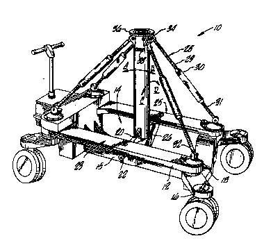
Fig. 1 is a perspective view of the present crane arm
dolly;

094/1~2 ~ 7 ~1 ~ PCT~S93/~1
Fig. 2 is a front end view thereof with the crane arm
dolly on level ground; and
Fig. 3 is a front end view thereof showing the crane
arm dolly on inclined ground.
DETAILED DESCRIPTION OF 1~ ~ ç~v 13NBODIIIB~T
Turning in detail to the drawings, as shown in Fig. 1,
the present crane arm dolly 10 includes a dolly chassis
12. The dolly chassis 12 is preferably a HYBRID dolly,
from Leonard Studio Equipment, Inc., North Hollywood,
California, with the dolly arm and hydraulic system
removed, leaving a central open space 14. Of course,
other dollys may also be used. The legs 16 of the dolly
chassis 12 are reinforced, as is the central chassis
section 15, and gusset plates 17 and webs 19 are added
chassis 12, to increase the weight carrying capacity of
the dolly chassis 12. Hollow king pins 18 link the dolly
chassis and legs 16 at the front and rear outside corners
of the crane arm dolly 10, as is known in the art.
A cross bar 20 extends across the central open space
14, at the central chassis section 15. The cross bar 20
is attached to the dolly chassis 12 by spaced apart cross
bar pivot connections 22, with one pivot connection 22 on
each side 23, 25 of the dolly chassis 12. A post 2~ is
pivotally connected to the cross bar 20 by a post pivot
connection 26. Consequently, the post 24 can pivot in the
front to back direction (indicated by the A-B arrow) as
well as in the lateral side to side direction (as indicat-
ed by the C-D arrow).
A king pin clevis 32 is pivotally supported within
each of the four hollow king pins 18. A post support rod
28 extends from each king pin clevis 32 to a post clevis
34 at the top end of the post 24. A post support rod
adjustor 30 is provided on each post support rod 28. The
post support rod adjustors 30 can lengthen or shorten the
post support rods 28 in a "turnbuckle" manner as the post

094l1~2 ~1 5 1 7 ~1 ~ PCT~S931l2l~
support ends 29 and 3~ have oppositely running left and
right hand threads.
A mounting plate 36 is attached at the top of the post
24. Window levels 38 on the post 24 indicate the front to
back and side to side inclination of the post.
In use, a crane arm is attached to the mounting plate
36. The dolly chassis 12 includes a dolly steering
system, such as, for example, the steering systems dis-
closed in Chapman, U.S. Patent No. 5,174,593; Fabiano,
U.S. Patent No. 4,950,126; and Fisher, U.S. Patent No.
4,257,619, all incorporated herein by reference. Of
course, the HYBRID dolly steering system can also be used.
In each steering system, a steering handle steers the
dolly wheels via chains and sprockets within the dolly
chassis. The crane arm dolly carrying the crane arm and
camera is steered and pushed by operators or "grips", to
maneuver the camera supported on the end of the crane arm
to the desired camera angle position.
Where the crane arm dolly 10 operates on inclined
ground, as shown in Fig. 3, the post 24 can be leveled by
- adjusting the post support rod adiustors 30. Specifical-
ly, as shown in Fig. 3, with the right side of the camera
arm dolly 10 on inclined ground and raised above the left
side, the post support rod adjustors 30 on the left side
23 are turned to lengthen the post support rods 28 on the
left side of the dolly, while the post support rod adjus-
tors 30 on the right side of the dolly are turned to
shorten the right side post support rods 28, to bring the
post 24 to a vertical position. The post support rod
adjustors 30 are turned incrementally or simultaneously to
prevent binding. The window levels 38 indicate when the
post 24 is purely vertical, or the post deviation from
vertical. During adjustment of the post 24, each king pin
clevis 32 pivots slightly to compensate for post movement
and to prevent binding. Thus, a crane arm dolly is
disclosed for use on level and inclined ground.

Representative Drawing
A single figure which represents the drawing illustrating the invention.
Administrative Status

2024-08-01:As part of the Next Generation Patents (NGP) transition, the Canadian Patents Database (CPD) now contains a more detailed Event History, which replicates the Event Log of our new back-office solution.

Please note that "Inactive:" events refers to events no longer in use in our new back-office solution.

For a clearer understanding of the status of the application/patent presented on this page, the site Disclaimer , as well as the definitions for Patent , Event History , Maintenance Fee  and Payment History  should be consulted.

Event History

Description Date
Inactive: IPC from MCD 2006-03-11
Time Limit for Reversal Expired 1999-12-14
Application Not Reinstated by Deadline 1999-12-14
Deemed Abandoned - Failure to Respond to Maintenance Fee Notice 1998-12-14
Application Published (Open to Public Inspection) 1994-07-07

Abandonment History

Abandonment Date Reason Reinstatement Date
1998-12-14

Maintenance Fee

The last payment was received on 1997-11-26

Note : If the full payment has not been received on or before the date indicated, a further fee may be required which may be one of the following

  • the reinstatement fee;
  • the late payment fee; or
  • additional fee to reverse deemed expiry.

Please refer to the CIPO Patent Fees web page to see all current fee amounts.

Fee History

Fee Type Anniversary Year Due Date Paid Date
MF (application, 4th anniv.) - standard 04 1997-12-15 1997-11-26
Owners on Record

Note: Records showing the ownership history in alphabetical order.

Current Owners on Record
LEONARD STUDIO EQUIPMENT, INC.
Past Owners on Record
LEONARD T. CHAPMAN
Past Owners that do not appear in the "Owners on Record" listing will appear in other documentation within the application.
Documents

To view selected files, please enter reCAPTCHA code :


To view images, click a link in the Document Description column. To download the documents, select one or more checkboxes in the first column and then click the "Download Selected in PDF format (Zip Archive)" or the "Download Selected as Single PDF" button.

List of published and non-published patent-specific documents on the CPD .

If you have any difficulty accessing content, you can call the Client Service Centre at 1-866-997-1936 or send them an e-mail at CIPO Client Service Centre.


Document
Description 
Date
(yyyy-mm-dd) 
Number of pages   Size of Image (KB) 
Cover Page 1995-12-01 1 16
Description 1994-07-07 3 137
Abstract 1994-07-07 1 53
Claims 1994-07-07 1 22
Drawings 1994-07-07 2 79
Representative drawing 1998-06-29 1 23
Courtesy - Abandonment Letter (Maintenance Fee) 1999-01-11 1 184
Fees 1996-09-30 1 94
Fees 1995-10-10 1 47
International preliminary examination report 1995-06-13 6 108
PCT Correspondence 1995-07-28 1 24