Note: Descriptions are shown in the official language in which they were submitted.
CA 02152220 2000-02-15
- 1 - 94-ECC-053
MONITORING DEVICE SECURED TO POWER
DISTRIBUTION SYSTEM CONDUCTORS
BACKGROUND OF THE INVENTION
Field of the Invention
This invention relates to monitoring current and voltage in branches of
an ac electrical power distribution system, and more particularly to apparatus
which
can be locked to the conductors of the ac distribution system at any location
along the
conductors.
Ba~c Eround of Information
U.S. patent number 5,315,531 discloses a system for monitoring
the energy consumed at multiple locations below the electric meter which is
typically installed by a utility on the main power lines serving a customer.
This system allows the customer to determine consumption for each
location below the meter and allocate costs accordingly, if desired.
The energy monitoring system includes a modular unit at each location
to be monitored. Each modular unit has a toroidal coil inductively coupled to
each
phase conductor of the ac distribution system by passing the conductor through
the coil.
The coils are mounted in a housing having through passages extending through
the
_ 21~22~~
= 2 - 94-ECC-053
The coils are mounted in a housing having through passages extending through
the
toroidal coils so that the conductors pass completely through the housing.
Stabs
extending from the housing adjacent the through passages engage the terminals
on a
circuit breaker together with the ac conductors to provide a voltage pick-up
for the unit
and to secure the unit to the circuit breaker. Thus, these units are referred
to as piggy
back units since they are mounted to the circuit breaker.
The piggy back units include circuitry which digitizes the analog currents
and voltages sensed by the toroidal coils and the stabs, respectively, and
calculates
power and energy consumed utilizing an on board microprocessor. The energy
monitoring system also includes a central, personal computer (PC) which is
linked to
each of the piggy back units by a simple two-wire synchronous communication
line
daisy chained between the units and the PC. The PC gathers the calculations
generated
by each of the local units for use in allocating billing.
The piggy back units are dimensioned to match the dimensions of the
circuit breaker and can be secured to the circuit breakers mounted in a load
center
without requiring modifications to either the circuit breaker or the load
center. There
is a need; however, to be able to tap the monitoring units into the power
distribution
system at locations other than at a conductor termination, as is currently
required for
the voltage stab.
There is a further need for a monitoring apparatus which can monitor
the current and voltage at any point along the conductors of the power
distribution
system and which does not require stripping of the conductor for the voltage
connection.
There is also a need for such a monitoring apparatus which can lock the
monitoring unit simply to any location along the conductor.
SUMMARY OF THE INVENTION
These needs and others are provided by the invention which is directed
to apparatus for monitoring current and voltage and for making energy
calculations
therefrom and which can be locked to any point along the electrical conductors
of an
ac power distribution system. In particular, the apparatus includes a housing
having
through passage means extending completely through the housing. A separate
through
passage is provided for each of the conductors. Combination mounting and
voltage
sensing means include elongated electrically conductive fastener means
extending from
- --3 - ~ ~ ~ ~ ~ ~ ~ 94-ECC-053
the housing laterally into the through passages. These fasteners have pointed
ends
which pierce insulation on the conductors to electrically contact and
mechanically
clamp the electrical conductors passing through the passages. The housing
includes
toroidal coil means, one toroidal coil for each conductor through which the
through
passages, and therefore, the electrical conductors pass, to inductively sense
the currents
in the conductors. The housing also includes circuitry connected to the
toroidal coils
for measuring the currents and connected to the electrically conductive
fasteners to
measure the voltages. Preferably, this circuitry includes analog to digital
converter
means for digitizing the analog currents and voltages detected by the toroidal
coils and
the fasteners, respectively, and digital processing means for calculating
energy
consumed. Also preferably, the apparatus includes a communications link for
communication with a remote control unit.
The elongated, electrically conductive fasteners are preferably threaded
into electrically conductive support blocks recessed in openings in the
housing and
which are covered with removable electrically insulating closures to protect
personnel
from contact with the fasteners which are at line voltage.
An electrically insulating sleeve fills in the through passage around
smaller diameter conductors. The pointed ends of the elongated electrically
conductive
fasteners penetrate this sleeve as well as the insulation on the conductor.
The invention provides a simple compact monitor which can be easily
and quickly installed at any point along the conductors of an ac power
distribution
system for monitoring current and voltage.
BRIEF DESCRIPTION OF THE DRAWINGS
A full understanding of the invention can be gained from the following
description of the preferred embodiments when read in conjunction with the
accompanying drawings in which:
Figure 1 is a schematic diagram of an ac power distribution system to
which the invention has been applied.
Figure 2 is a front elevation view of a monitoring unit in accordance
with the invention shown mounted on three phase conductors of the distribution
system.
Figure 3 is a bottom plan view of the monitoring unit of Figure 2.
Figure 4 is a vertical section view through the monitoring unit taken
along the line 4-4 in Figure 2 shown with the conductor removed.
CA 02152220 2000-02-15
- 4 - 94-ECC-053
Figure 5 is a fragmentary view illustrating a combined mount and
voltage tap which forms pan of the monitoring unit of Figures 2-4 shown
mounted on
a printed circuit board (PCB) and engaging a conductor of the distribution
system.
Figure 6 is a vertical sectional view through the assembly shown in
Figure 5 taken along the line 6-6.
Figure 7 is a laid open view of the PCBs of the monitoring unit showing
the current sensing coils, voltage taps and circuitry mounted thereon.
DESrR~nN OF THE PREFERRED EMBODIMENTS
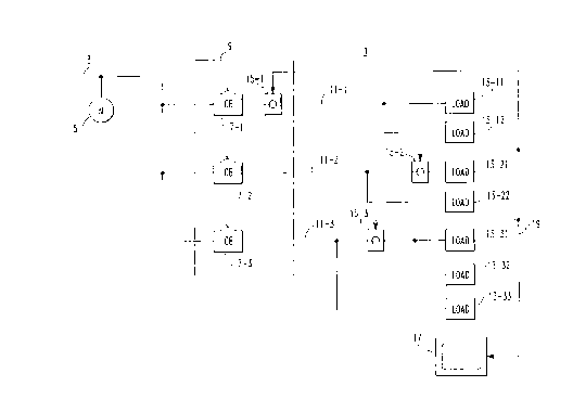
Figure 1 illustrates a secondary ac power distribution system 1 to which
the invention has been applied. The secondary ac power distribution system 1
includes
a main ac line which provides power generated by the electric utility. The
utility
places a meter 5 on the main ac line to measure energy consumed by the
distribution
system 1. The main ac line 3 is connected to a number of circuit breakers 7-1
to 7-3
mounted in a panel board or load center 9. Each of the circuit breakers 7
provides
protection for a circuit which includes a load conductor 11 providing power to
a load
13.
The conductors 3 and 11 are all represented by a single line for
simplicity, but it should be understood that all of these conductors can be
multiphase
as explicitly shown below. In order to be able to monitor the energy consumed
by the
individual loads 13, an individual monitoring unit 15-1 to 15-3 is placed on
the
conductors 11-1 to 11-3 for each of the loads 13-11 to 13-33. In accordance
with the
invention, these monitoring units 15-1 to 15-3 can be placed anywhere in the
distribution system, including anywhere along the conductors 11-1 to 11-3,
because
unlike the earlier monitoring units described in U.S. patent number
5,315,531 the monitoring units 15-1 to 15-3 do not have to be mounted
directly on the circuit breakers 7-1 to 7-3. Thus, as seen in Figure 1, the
monitoring unit 15-1 can be placed in the panel board or load center 9 where
it monitors energy consumed by all of the loads 13-11 and 13-12 protected by
an individual circuit breaker 7-1. On the other hand, where the energy
consumed by an individual load such as the load 13-21 is of interest, the
monitoring unit 15-2 can be placed adjacent the load. Obviously, the
invention provides a great deal of flexibility such that a monitoring unit
such as 15-3 can monitor multiple loads 13-31 and 13-32, but not all of the
loads (not 13-33) on a particular circuit.
CA 02152220 2000-02-15
- 5 - 94-ECC-053
The monitoring units 15-1 to 15-3 monitor the current and voltage, in
a manner to be discussed below, in the conductor to which they are coupled and
calculate.power and energy consumed. Except as described below, the units 15-1
to
15-3 are the same as those described in U.S. patent 5,315,531. As described in
the patent, the individual monitoring units 15-1 to 15-3 are linked to a
central unit such as represented by the personal computer (PC) 17 in Figure 1
through a communications link 19, which in the illustrated embodiment is
an Industrial Communication (INCOMTM) system. The INCOM
communications system utilizes a simple two wire synchronous
communication line which is daisy chained to the several monitoring units
15-1 to 15-3 and the PC 17. The PC 17 digitally addresses each of the
monitoring units 15-1 to 15-3 in a master - slave relationship for the purpose
of gathering the data generated by the individual monitoring units for
cental processing and allocating appropriate portions of the total billing
determined by the meter 5 to the local users.
Turning to Figures 2 and 3, the monitoring units 15 comprise a housing
21 which includes a molded casing 23 with a molded cover 25. A through passage
27A - 27C provided for each phase of the conductor 11 passes completely
through the
housing 21. As shown in Figure 4, a tubular portion 29 of the casing 23 and a
mating
tubular portion 31 of the cover 25 form the thmugh passages 27. A toroidal
coil 33A
to 33C is mounted within the housing 21 concentric with each of the through
passages
27A - 27C. These toroidal coils 33A - 33C are mounted on a printed circuit
board
(PCB) 35. A combined mount and voltage tap 37 as best seen in Figures S and 6,
comprises an electrically conductive support block 39 which is pinned or
soldered to
a second PCB 41 having openings 41A, 41B and 41C which align with the opening
27A-27C. The support block 39 has a threaded through bore 43. An elongated
threaded fastener 45 is threaded into the threaded bore 43 and extends
generally
radially into the associated through passage 27. The elongated threaded
fastener 45 has
a sharpened point 47. Both the fastener 45 and the support block 39 are
preferably
made of copper plated with silver for good electrical conductivity.
As shown in Figures 4-6, the phase conductors 11 for the load to be
monitored are passed through the though passages 27A-27C. And thus through the
toroidal coils 33A-33C which inductively sense the current flowing in the
conductors.
Each elongated fastener 45 which is slotted at 49 is accessible through an
opening 51
CA 02152220 2000-02-15
- 6 - 94-ECC-053
in the housing 21. A screw driver engages the slot 49 to thread the fastener
through
the block 39 into the passage 27A-27C. The pointed end 47 of the fastener 45
penetrates the insulation 53 on the conductor 11 and the conducting wire 55 to
thus
make electrical contact with the wire 55. Fastener 45 also mechanically clamps
the
conductor 11 within the through passage 27 to thereby lock the monitoring unit
15 to
the conductor. Normally the passage 51 is plugged with an insulating plastic
plug 57
to prevent an inadvertent contact with the fastener 45 which is at line
potential.
The through passages 27 are sized to accommodate various size
conductors. For conductors smaller than the maximum size that can be
accommodated,
an insulating sleeve 59 is provided which allows the smaller conductor to be
clamped
with its axis concentric with that of the toroidal coil 33. (See Figure 3).
The pointed
end 45 also penetrates this sleeve 59.
As seen in Figure 7, the electrically conductive support blocks 39 are
connected by resistors 61 to PCB 35 on which the coils 33A-33C are mounted on
the
PCB 41. As described in detail in patent number 5,315,531, the analog voltage
signals
derived by the combined mount and voltage taps 37, and the analog current
signals
generated by the toroidal coils 33, are transferred by ribbon connector 63 to
PCB 41
where they are converted to digital signals for calculation of the energy
consumed by
circuits identified generally by the reference character 65. The circuitry 65
can include
the custom Sure PIusTM integrated circuit chip (IC) described in U.S. patent
number 5,270,898. This IC includes an analog to digital converter, a
microprocessor and a communications interface by which the calculated
energy consumed is provided to the communications link 19 through a
connector 67 in the housing 21.
While specific embodiments of the invention have been described
in detail, it will be appreciated by those skilled in the art that various
modifications and
alternatives to those details could be developed in light of the overall
teachings of the
disclosure. Accordingly, the particular arrangements disclosed are meant to be
illustrative only and not limiting as to the scope of invention which is to be
given the
full breadth of the claims appended and any and all equivalents thereof.